

Page 1
DE1851 1
,5,5
Indoor Photo-Electric Infrared Beam Barrier
Installation Instructions
,1752'8&7,21
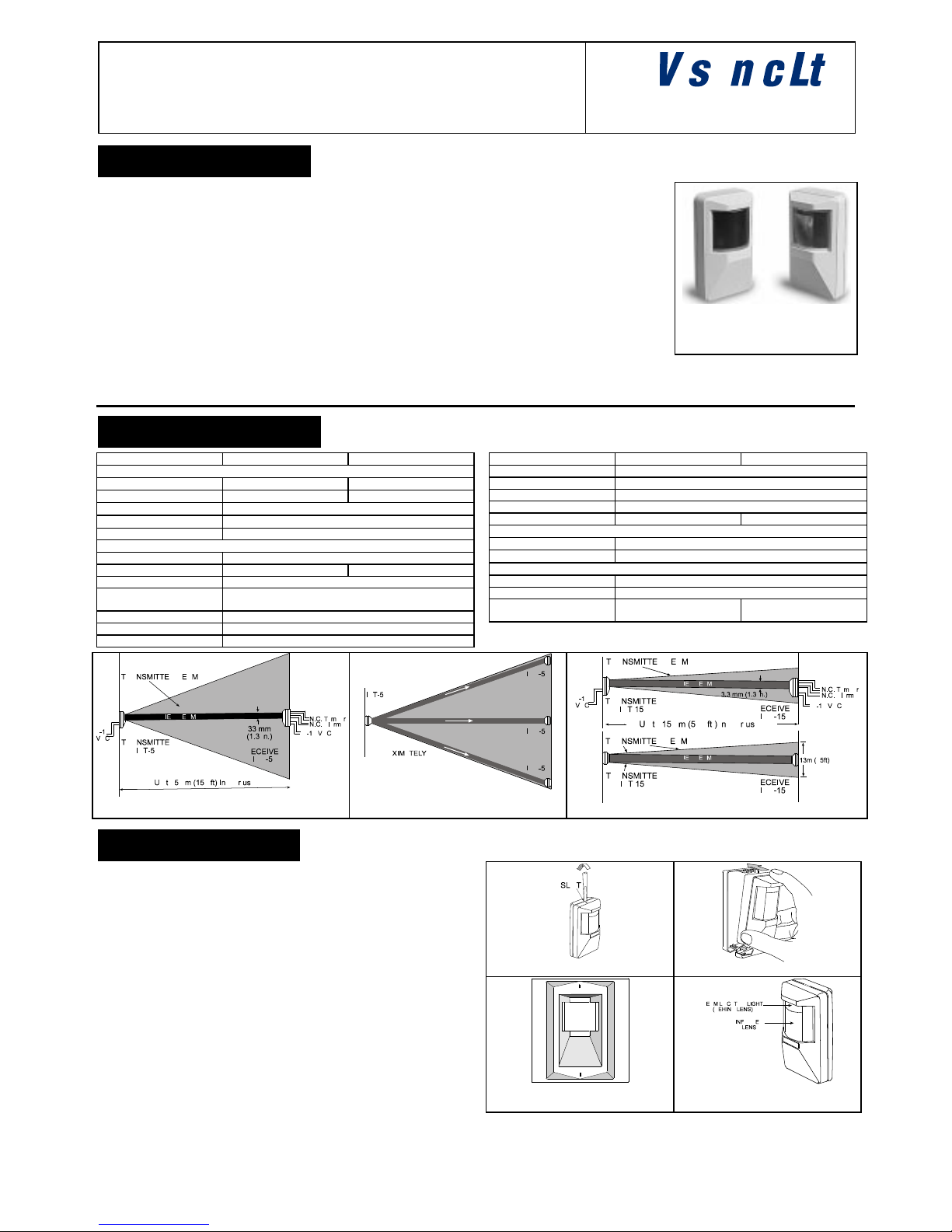
IR-50 and IR-150 are pulse-modulated photoelectric infrared
beam barrier designed for indoor residential, commercial and
industrial applications. The system consists of a transmitter
producing a wide angle (IR-50) or concentrated (IR-150) invisible
infrared beam towards a narrow-angle receiver. Visible Beam
Locator light in the receiver (IR-50) or in the transmitter and the
receiver (IR-150), provide quick and easy alignment without
special tools or test equipment.
The transmitted beam is generated by 2 powerful infrared LEDs.
The 40° wide angle beam of IR-50 allows multiple receiver
installations using a single transmitter. The 6° receiver field of
view provides a large safety margin to prevent false alarms. Yet it
is narrow enough to eliminate reception of reflected beam. Internal
built-in optical filter prevents unwanted light penetration, other
than the infrared wavelength.
The system is immune to
fluorescent radiation, flickering
lights and indirect sunlight.
State-of-the-art electronic
circuitry provides protection
against RF interference and
supply voltage transients.
The transmitter emits an invisible
beam, to the receiver. When an
intruder crosses this beam
barrier, the receiver’s internal
alarm relay deenergizes.
IR-50 Transmitter & Receiver
Note: External view of IR-150
transmitter & receiver is similar.
The receiver’s walk test LED lights at the same time (when LED
selector is in Walk position, see par. 3.4). After crossing, the relay
again energizes and the LED extinguishes.
63(&,),&$7,216
FEATURE IR-50 IR-150
OPTICAL
Range (**)
Up to 50m (150 ft) Up to 150m (500 ft)
Transmitter beam width
40° (*) 6° (*)
Receiver field of view
6°(*)
Adjustment
Vertical +10° to 20°. Horizontal 30°.
Beam Locators Visible Beam Locator built into receiver and transmitter
ELECTRICAL
Voltage 9 - 16VDC (protected against reverse polarity)
Transmitter current 20mA 15mA
Receiver current 15mA
Relay output Normally closed (fail-safe) contacts. 18 ohm resistor in
series with contacts. Rating - 0.5A resistive/24 VDC.
Alarm period 2 - 3 seconds
Tamper contacts Normally closed. Rating - 0.5A resistive/24 VDC.
LED Three selectable operation modes
FEATURE IR-50 IR-150
Infrared source Long-life Gallium Arsenide LED
Infrared sensor PIN photodiode
Transmitter Frequency 1 kHz, 10 microsecond pulse width
IR wavelength 950 nm
Receiver type (Qty.) IRR-50 (one or multiple) IRR-150 (one)
ENVIRONMENTAL
Operating temperature
-10°C to 50°C (14°F to 122°F)
Storage temperature
-20°C to 60°C (-4°F to 140°F)
PHYSICAL
Dimensions 120 x 70 x 48 mm (4.7 x 2.7 x 1.9 in)
Weight 220 g (0.48 lb)
Colors Dark beige standard
cream/ white also available
Dark beige or standard
white
*
Typical, horizontal and vertical.
**
distance between transmitter to receiver
Figure 1A.
IR-50 Side View Beam Pattern
Figure 1B.
IR-50 Top View - Multiple
Receivers
Figure 2.
IR-150 View Beam Pattern
,167$//$7,21
6HOHFWLQJ0RXQWLQJ/RFDWLRQ
A. Select mounting locations / height for the transmitter and
receiver(s) so that an intruder will cross the beam(s). The
receiver and transmitter should be mounted facing each other,
and their angular back housing allow installation directly onto a
wall (surface mount), or in a corner. They may also be
flush-mounted using optional bracket SRF-201. (Fig. 5).
B . Prevent receiver’s lens exposure to direct sun light, to prevent
false alarm.
C . For maximum reliability, locate the receiver as far as possible
from fluorescent light or flickering lights.
NOTE: The transmitter unit is not sensitive to any of the above
disturbance sources and may be placed wherever desired.
0RXQWLQJ
A. Insert a small screw driver into the slot on top of the unit, press
lightly down and remove the cover.
Figure 3. Cover Removal
Figure 4. Cover Replacement
Figure 5. Flush Mounting
Bracket SRF-201
Figure 6. Beam Locator Light
Side View
Top View
Page 2
2 DE1854
B. Mount the base (with the P.C. board) in the selected location
and height for optimum coverage. For surface mounting use
the 2 base rear knockout holes. For corner mounting use the
angled sides knockouts. The unit(s) must be fastened tightly to
the mounting surface to avoid vibrations.
C . To close the front cover (after wiring), insert the legs, located
on the bottom of cover, into their respective slots in the bottom
of the base and close by exerting slight downward.
:LULQJ
A. To route wires into the housing, use either the wiring
knockouts or one of the lower circular mounting knockouts.
B. Wiring the receiver
1) Connect Tamper N.C. terminals
to control panel normally
closed 24h protection zone.
Tamper contact opens when
cover is removed.
Figure 7 - Terminal Block
Wiring - Receiver
2) Connect Relay N.C. terminals to control panel normally
closed burglar protection zone. Relay contacts opens when
an intruder is detected or during power loss.
3) Connect the 12VDC (+) and (-) terminals to 9-16VDC
power source and verify correct polarity. Multiple receivers
(IR-50 only) should be connected in parallel.
C. Wiring the transmitter
The transmitter requires only the connection of the supply
voltage (9 -16 VDC) to the 12VDC (+) and (-) terminals.
Note: It is advisable to use power supply with battery back-up.
$OLJQPHQW
Receiver and transmitter alignment is accomplished with Visible
Beam Locator lights that operate through the upper section of the
receiver’s lens (for IR-150: receiver and the transmitter) (Fig. 6).
The receiver should be aligned horizontally and vertically so that
the LED light is fully visible through the Beam Locator section of
the lens when viewed from the transmitter. The transmitter is then
similarly aligned, using the transmitter Beam Locator light.
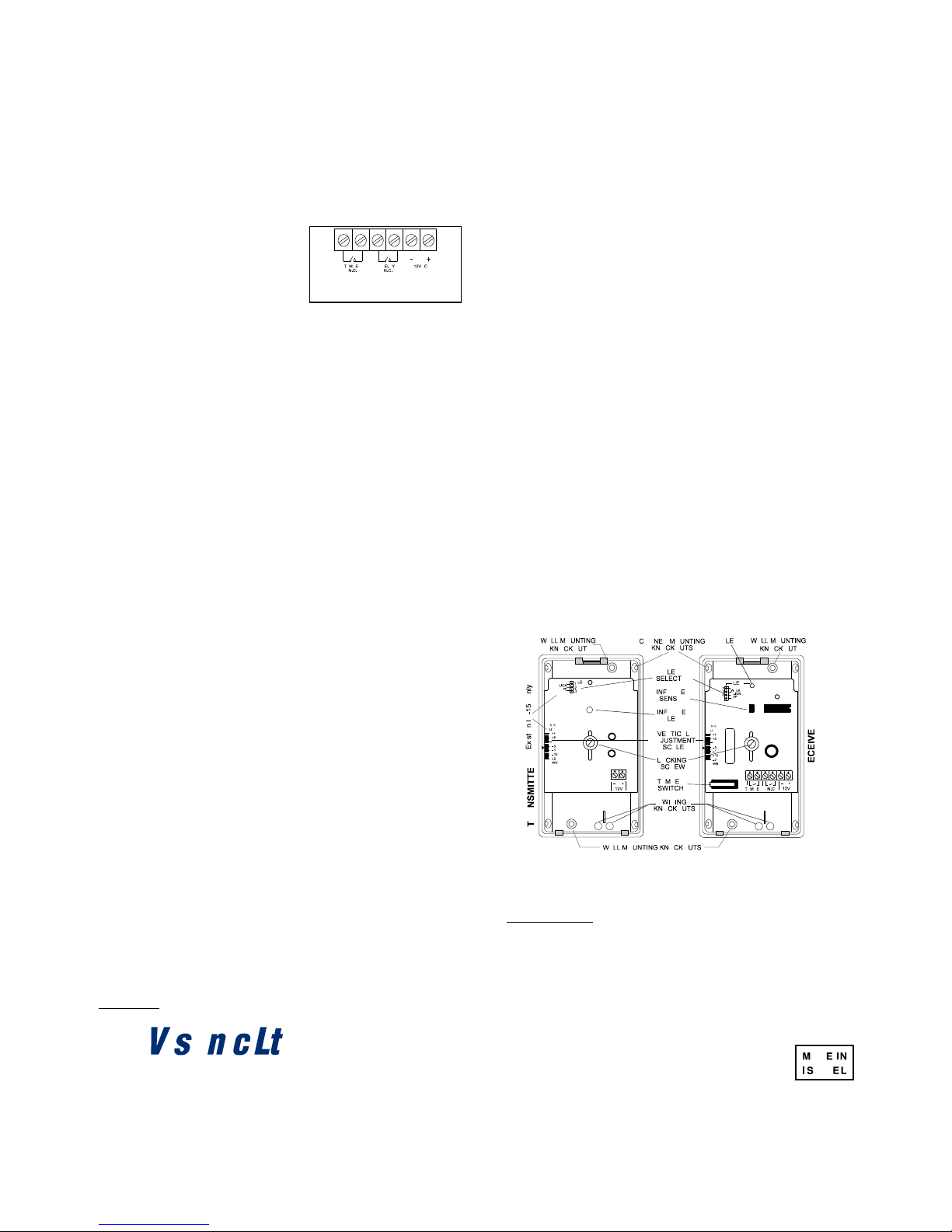
Three mode LED selector
The receiver’s LED selector consists of a 4-pin connector and a
jumper which can be inserted to link two pins, enabling three
operational modes:
A. WALK/ALARM (Jumper links pins 1-2) - This mode is used for
walk testing. The LED lights up for 2-3 seconds whenever the
beam is interrupted.
B. ALIGN (Jumper links pins 2-3) - This mode is used for
aligning. The LED lights continuously to enable convenient
observation of the red light in the beam locator lenses (Fig. 6.)
C. OFF (Jumper links pins 3-4) - This mode can be used to
disable the LED after final test is completed, to prevent
unauthorized persons from tracing the direction of the beam.
Note: The LED mode selection does not interfere with alarm relay
operation, which will signal whenever the beam is interrupted.
For IR-150: The LED selector in the transmitter lRT-150 enables
only two operational modes: ALIGN and OFF.
For aligning, move the jumper of the LED selector in both units to
ALIGN. The LEDs should light continuously.
Horizontal Alignment
The field of view of each unit can be adjusted horizontally
approximately 30°, by rotating the lens to the left or right. To
adjust, remove the lens-locking devices, located on both sides of
the lens, by pushing them from the inside of the cover. Rotate the
lens carefully to the desired position. Holding firmly in place, insert
locking devices from outside (ridges pointed outward) and firmly
push into place until a click is heard. The transmitter is aligned
similarly, using its Beam Locator light.
For IR-50: To align, look towards the receiver from the transmitter
location. Move to the left and to the right of the transmitter, to
determine the area in which the Beam Locator light on the
receiver is fully visible. Align the receiver's lens, so that the center
of the area in which the Beam Locator light is fully visible will be
approximately at the place where the transmitter is located.
Vertical Adjustment
The P.C. board vertical adjusting scale (IR-150: in both units) and
the plastic pointer on the base indicate the approximate vertical
angle in degrees between the receiver's (for IR-150: receiver’s or
transmitter's) line of sight and the horizontal line of the unit.
To change the vertical adjustment, loosen the screw which
fastens the printed circuit board to the base. Slide the P.C. board
up or down to the desired angle and tighten the screw firmly.
To align the receiver, look toward the receiver from the transmitter
location. Align the receiver (vertically) so that the Beam Locator
light will be fully visible from the floor level below the transmitter
and up to the same distance above the transmitter (provided the
distance between the transmitter and receiver is at least 20 times
larger than their height from the floor). The transmitter is aligned
similarly, using the Beam Locator light on the transmitter.
)LQDO7HVW
The system should be checked at least once a week as follows:
A . Move the LED selector jumper to 'WALK' position. Replace
the receiver front cover [IR-50: receiver(s)]. The LED should
go off, indicating correct alignment of the receiver.
B. Walk-test by crossing the path between the transmitter and
receiver [IR-50: receiver(s)]. The receiver LED should light for
2-3 seconds indicating alarm condition caused by interruption
of infrared beam barrier. This test should be performed with all
fluorescent lights at the protected area turned on.
C . Determine the signal margin by slowly covering the receiver
lens from the bottom upward (using a piece of cardboard) until
the LED lights up. The ratio between the size of the covered
lens area and the total lens area (excluding the Beam Locator
area) indicates the signal margin of the system. If alignment is
correct, the signal margin should be more than 35 percent.
D . Move the jumpers (IR-150: in both units) from 'WALK' to 'OFF'
position to disable the LED and prevent unauthorized persons
from ascertaining the path(s) of the infrared beam barrier(s).
The user should be instructed to cross the infrared barrier to
assure an alarm output prior to each system arming.
Figure 8. Printed Circuit Board
$YRLGLQJ5HIOHFWHG%HDP3DWKV
Eliminate reflected beams as follows:
A. For IR-50 only: Apply piece of black insulation tape on inner
side of transmitter window, to narrow the transmitter beam and
allow emission of infrared energy only in the receiver direction.
B. Change the receiver alignment (for IR-150: of receiver and
transmitter), adjusting them away from the reflecting surface.
C. Reduce receiver’s sensitivity by lens partial covering (from
inside). When the reflected beam barrier is eliminated recheck
system signal margin (para. 3.5c.).
VISONIC LTD (ISRAEL):
P.O.B 22020 TEL-AVIV 61220 ISRAEL. PHONE: (972-3) 645-6789, FAX: (972-3) 645-6788
VISONIC INC. (U.S.A.):
10 NORTHWOOD DRIVE, BLOOMFIELD CT. 06002-1911. PHONE: (860) 243-0833, (800) 223-0020 FAX: (860) 242-8094
VISONIC LTD. (UK):
UNIT 1, STRATTON PARK, DUNTON LANE BIGGLESWADE, BEDS. SG18 8QS. PHONE: (01767) 600857 FAX: (01767) 601098
VISONIC LTD. 1998 IR-50 / IR-150 D-1851-0 NEW: DE1851- (REV. 1, 7/98). WARRANTY STATEMENT IS AVAILABLE UPON REQUEST.
 Loading...