

Page 1
IPI-4 Converter
For AXS-100/200 Controllers
Introduction
The IPI-4 Adapter is an integrated single-port PCB type
asynchronous serial communication gateway that seamlessly
converts the RS-232 port of a VisAccess AXS-100/200 controller
to 10/100 Ethernet V2.0 (TCP/IP).
The adapter enables a ‘Master’ AXS-100/200 controller to be
placed anywhere on a WAN/LAN or Internet based network and
still perform as if the controller was hard wired to the host
computer via RS-232.
The IPI-4 is shipped with Lantronix Programming Software for
browser based configuration of its network settings, serial-port
line settings, UART transmit and receive buffer trigger levels and
serial port flow control.
The IPI-4 also supports remote configuration, supervision and
management via EIRIS V4.6 (or higher) as well as AXSalert
(all versions) enterprise software.
NOTE: RJ-45 terminated Ethernet network interface cables are
not included with the IPI-4 converter.
CAUTION: It is important that the installer understand
and follow the instructions in this document. If you have
questions, call your local VT support representative.
Installation Guide
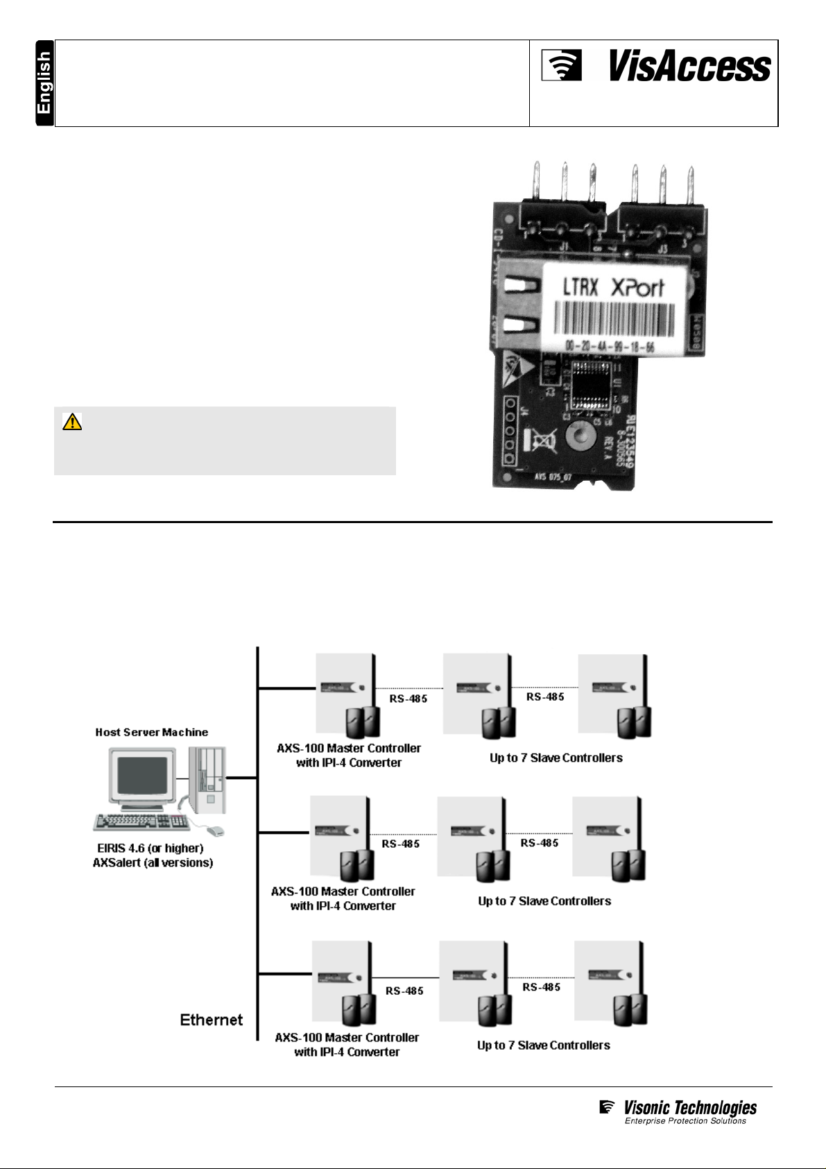
Typical System Configuration
Any combination of eight Master/Slave AXS-100/200 controllers (each with its own address) can be networked together on a single
RS-485 data loop to manage up to 16 doors. Each RS-485 data loop requires that one Master controller (whose address is #1)
be equipped with an IPI-4 Converter for communicating via 10/100 Ethernet V2.0 (TCP/IP) with the host server machine.
Page 1 of 6
D-301285_V6.0
Page 2
IPI-4 Converter – Installation Guide
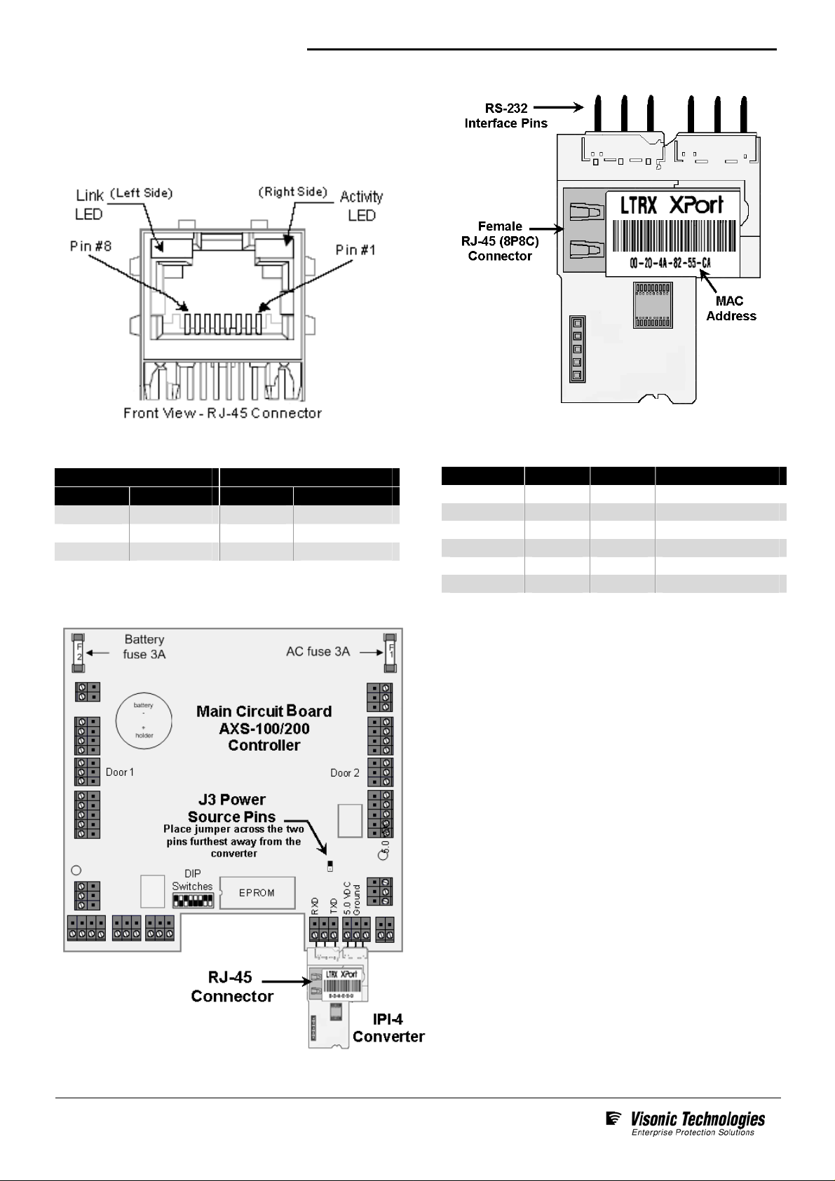
Electrical Interfaces
The IPI-4 contains one female RJ-45 (8P8C) connector for
linking the device to the LAN/WAN Ethernet network switch or
router. This requires a standard network 8-pin RJ45 terminated
patch cable (not included)
The pin configuration of the RJ-45 connector is detailed below:
Two bi-color Ethernet status LEDs are built into the front of the
Female RJ-45 connector as detailed below:
Link LED (Left Side) Activity LED (Right Side)
Color Meaning Color Meaning
Off
Amber
Green
No Link
10 Mbps
100 Mbps
Off
Amber
Green
No Activity
Half-duplex
Full-duplex
Installation and Hookup Details
The IPI-4 also utilizes a 6 pin-rigid integrated connector for
connecting the converter to the AXS-100 master controller’s
RS-232 interface as detailed in the table below
Signal Dir Pin Function
RXD In 1 Serial Data
None 2 Not Used
TXD Out 3 Serial Data
+5.0 VDC In 4 Power
- 5 Ground
Not Used 6 Not Used
1. Ensure tht the controller the IPI-4 is to be installed has
been set to position # 1 on the AXS-100 loop.
2. Power-down the AXS-100 controller and connect the
IPI-4 to the serial interface of the controller as shown.
3. To ensure that the controller will provide power to the
IPI-4, place J3’s power source jumper across the two
pins furthest away from the converter.
4. Using a RJ-45 terminated patch cable (not included)
connect the IPI-4 to the LAN/WAN Ethernet network
switch or router.
5. Power-up the AXS-100 controller; the IPI-4 converter will
also power-up and link to the Ethernet network.
Page 2 of 6
D-301285_V6.0
Page 3

IPI-4 Converter – Installation Guide
Initial Configuration and What You Need To Know
Configuration should be carried out as soon as the installation is completed. It is important that the installer have a basic understanding
of Ethernet setup in order to initially configure the IPI-4 Converter. If you do not have this basic knowledge, please seek the proper
assistance.
Before proceeding with remote management of the device via EIRIS or AXSalert enterprise software; you need to know the IPI-4
converter’s unique IP address on the LAN/WAN network. Several options for determining the IP address of the device are available.
We recommend that you simply PING the device. Alternatively you can use the enclosed Lantronix_Programming application to assign
an IP address to the converter.
Pinging the IPI-4 Converter
1. In the Start Menu located on the far left side of the
Windows task bar select Start > Run; the Start, the
Run/Search Command dialogue box appears.
Using the Lantronix_Programming Application
The Lantronix_Programming application is supplied on the
enclosed CD. You can either run it directly from the CD or
copy it to any folder on the host EIRIS or AXSalert computer
and run the program from there.
1. Launch the Lantronix_Programming application;
the Lantronix IP Assigning box appears.
2. Type cmd in the free text field then click OK;
the MS Windows command interpreter (DOS shell)
box appears.
3. Type Ping ‘<MAC address>’; then press the Enter key
on your computer’s keyboard.
The IPI-4’s ‘MAC’ address can be found printed on the
product label glued to the top side of the RJ-45 connector.
2. Enter a temporary IP address for the IPI-4 that does not
conflict with any other components on the network. Next;
enter the MAC address of the adapter in the provided fields.
The IPI-4’s ‘MAC’ address can be found printed on the
product label glued to the top side of the RJ-45 connector.
3. Enable the For LANTRONIC option, then Click Run. When
prompted for a
Lantronix XPort Device Server
User Name and Password; click OK; the
browser window appears.
4. On the left side of the browser window, Click Network;
the Network Settings window appears.
If there is a response from the IPI-4, the IP address of
the device will immediately appear.
4. Record the returned IP address for use with either EIRIS
or AXSalert enterprise software.
Page 3 of 6
D-301285_V6.0
5. Enable the Use the following IP configuration option. Enter
appropriate IP, Subnet and Gateway data in the applicable
fields. Then click OK and finally click Apply Settings.
6. Record the entered IP address for use with either EIRIS or
AXSalert enterprise software
Page 4

IPI-4 Converter – Installation Guide
Configuring EIRIS for Remote Management
EIRIS 4.6 (or higher) can be configured to simultaneously monitor
and manage the access control hardware on multiple AXS-100
loops using Ethernet TCP/IP using separate TCP gateways
Each defined TCP Gateway enables the EIRIS server machine
(using a designated COM port) to bi-directionally communicate
with one Master AXS-100/200 controller via the IPI-4 adapter
Initial configuration is detailed in the procedure steps below. For
advanced functionality this document should be used in
conjunction with the EIRIS Configuration Guide - 4.6 (or higher).
1. Ensure that the Master controller (including the IPI-4) is
powered up and wired correctly to the EIRIS host machine via
the LAN/WAN
.
2. Launch EV2 and access Setup mode. Then Access the
Components tab in the Object Tree Pane
.
3. Right-click on the All Serial Interface tree branch, a shortcut
menu appears. Select Add by Type, an Add Object box
.
appears
.
.
6. Next, right-click on the All Access Control tree branch, a
shortcut menu appears. Select Add by Type; an Add Object
box appears.
7. Double-click the AS100 Loop
icon; the corresponding
AXS-100 configuration form appears. Then access the
Hardware configuration form. Update the Name of the
access control loop so that the new name denotes its
intended usage.
4. Double-click on the
TCP Gateway icon; the related
configuration form appears. Access the Settings tab of the
form and update the Name Parameter to signify the usage of
the TCP gateway.
5. Enter the IP Address of the IPI-4 converter. Then define the
converter’s IP Port (default = 10001). Last, press Apply, the
new TCP Gateway configuration data is saved to the EIRIS
database.
8. Using the I/O Channel pull-down menu, select the Serial
Interface that has been defined for the IPI-4
.
Page 4 of 6
D-301285_V6.0
9. Add Controller #1 (Master Controller) by clicking on the
relevant grayed-out controller icon. The selected controller
icon immediately appears black in color indicating that it how
active.
10. Ensure the relevant configuration data is saved to the EIRIS
database as well
as downloaded to the controller.
Page 5

IPI-4 Converter – Installation Guide
Configuring AXSalert for Remote Management
AXSalert (all versions) can be configured to simultaneously
monitor and manage the access control hardware on multiple
AXS-100 loops over a local area network (LAN) or a wide area
network (WAN) running TCP/IP using separate IP Ports
Each defined IP Port enables the AXSalert server machine
(using a designated IP port) to bi-directionally communicate
with one Master AXS-100/200 controller via the IPI-4 adapter
1. Ensure that the Master controller (including the IPI-4) is
powered up and wired correctly to the AXSalert host
machine via the LAN/WAN network.
2. Launch AXSalert; the main AXSalert window appears.
3. Access the Setup menu and click the Options command;
by default the Controller tab of the Setup window appears.
4. Access the Communication tab; press Add Port and
enable the IP Port option.
Should communication error boxes appear at anytime during
this procedure, press OK each time a message appears box in
order to bypass them.
5. In the field located to the right of the IP port option, enter
both the IP Address plus as well as the number of the IP
Port (default=10001). The IP address and
IP port number
MUST be separated by colon punctuation mark (“:”) as
shown in the example here: 62.0.18.235:300
.
.
.
Specifications & Order Details
Electrical Specifications
Input Voltage
Serial
Interface
Network
Interface
Compatibility
Data Rate
Supported
Protocols
Visual Indicators
5 VDC (+/-5%) via AXS-100 controller
RS-232 – 6 pin rigid Interface
Female RJ45, 10Base-T or 100base-
TX (auto-sensing)
Ethernet: Version 2.0/IEEE 802.3
115.2 Kbps
ARP, UDP/IP, TCP/IP, Telnet, ICMP,
SNMP, DHCP, BOOTP, TFTP, Auto IP
and HTPP
Amber LED: Link, Green LED: Activity
General Specifications
Construction
Dimensions
(L x W x D)
Weight
Operating
Temperature
& Humidity
Storage
Temperature
Browser-based
Configuration
Remote
Management
Standards
Compliance
Warranty
PCB board (no enclosure)
59.0 x 39.0 x 1.7mm
(2.32 x 1.54 x 0.67 inches)
15 grams (0.53 ounces) approx.
0°C to 80°C (32°F to 176°F)
05% to 90% non-condensing
0°C to 80°C (32°F to 176°F)
Lantronix Programming Software
EIRIS V4.6 or higher and
AXSalert (all versions)
EMI tested and complaint
One year limited warranty
(excluding batter)
Ordering Details
IPI-4 Converter
5-100482 IPI-4, Serial Port to Ethernet Adapter
Compatible Controllers
4-6280-4 AXS-100M, 2-door Controller, PCB only
3-6280-0
3-6280-1
AXS-100, 2-door Controller, Metal Box, 230
Transformer
AXS-100, 2-door Controller, Metal Box, 110
Transformer
Page 5 of 6
D-301285_V6.0
Page 6

IPI-4 Converter – Installation Guide
Standards Compliance
This device complies with the essential requirements and
provisions of Directive 1999/5/EC of the European Parliament
and of the Council of 9 March 1999 on radio and
telecommunications terminal equipment.
This device has been tested and found to comply with the limits
for a Class B digital device, pursuant to Part 15 of the FCC
Rules. These limits are designed to provide reasonable
protection against harmful interference in residential
installations. This equipment generates; uses and can radiate
radio frequency energy and, if not installed and used in
accordance with the instructions, may cause harmful
interference to radio and television reception. However, there is
no guarantee that interference will not occur in a particular
installation. If this device does cause such interference, which
can be verified by turning the device off and on, the user is
encouraged to eliminate the interference by one or more of the
following measures:
Re-orient or re-locate the receiving antenna.
Increase the distance between the device and the
receiver.
Connect the device to an outlet on a circuit different from
the one which supplies power to the receiver.
Consult the dealer or an experienced radio/TV technician.
Product Warranty
Visonic Technologies Ltd. (VT or the Company), and its affiliates,
warrants its products (hereinafter referred to as "the Product”) to be free
of defects in materials and workmanship under normal operating
conditions and use for a period of one year from the date of shipment
by VT. The Company’s obligations shall be limited within the warranty
period, at its option, to repair or to replace the defective Product or any
defective component or part thereof. To exercise this warranty, the
product must be returned to the manufacturer freight prepaid and
insured.
This warranty does not apply to repairs or replacement caused by
improper installation, Product misuse, failure to follow installation or
operating instructions, alteration, abuse, accident, tampering, repair by
anyone other than VT, external causes, and failure to perform required
preventive maintenance. This warranty also does not apply to any
products, accessories, or attachments used in conjunction with the
Product, including batteries, which shall be covered solely by their own
warranties, if any. VT shall not be liable for any damage or loss
whatsoever, whether directly, indirectly, incidentally, consequentially or
otherwise, resulting from a malfunction of the Product due to products,
accessories, or attachments of others, including batteries, used in
conjunction with the Product.
VT MAKES NO EXPRESS WARRANTIES EXCEPT THOSE STATED
IN THIS STATEMENT. VT DISCLAIMS ALL OTHER WARRANTIES,
EXPRESS OR IMPLIED, INCLUDING WITHOUT LIMITATI ON IMPL IED
WARRANTIES OF MERCHANTABILITY AND FITNESS FOR A
PARTICULAR PURPOSE. VT’S SOLE RESPONSIBILITY FOR
WARRANTY CLAIMS IS LIMITED TO REPAIR OR TO REPL ACE AS
SET FORTH IN THIS STATEMENT.
VT shall have no liability for any death, personal injury, property
damage, or other loss whether direct, indirect, incidental,
consequential, or otherwise, based on a claim that the Product failed to
function. However, if VT is held liable, whether directly or indirectly, for
any loss or damage arising under this limited warranty or otherwise,
regardless of cause or origin, VT's maximum liability shall be limited to
the purchase price of the Product, which shall be fixed as liquidated
damages and not as a penalty, and shall be the complete and exclusive
liability of VT.
VT World Headquarters * Tel Aviv, Israel * Tel: + 972 3 768-1400 * support@visonictech.com
VT Americas * Bloomfield, CT (USA) * Tel: 1-800-223-0020 * vta_support@visonictech.com
VT United Kingdom * Beckenham Kent BR3 90BF, U.K. * Tel: + 44-870-730-0840 * vtuk_support@ visonictech.com
Visonic GmbH * D-40215 Düsseldorf, Germany * Tel: + 49-0-211-600-696-0 * support@ visonictech.de
Additional information may be found at: www.visonictech.com
VT shall not, under any circumstances whatsoever, be liable for any
inaccuracy, error of judgment, default, or negligence of VT, its
employees, officers, agents, or any other party, or of the purchaser or
user, arising from any assistance or communication of any kind
regarding the configuration, design, installation, or creation of security
system involving the Product, that being the responsibility of the
purchaser or user.
If VT is unable to make such repair or replacement, VT’s entire liability
shall be limited to the cost of a reasonable substitute product. VT shall
not be responsible for any dismantling, installation, reinstallation,
purchasing, shipping, insurance, or any similar charges.
VT shall have no liability for any damages, including without limitation,
any direct, indirect, incidental, special, or consequential damages,
expenses, costs, profits, lost savings or earnings, or other damages
arising out of the use of the Product or the removal, installation,
reinstallation, repair or replacement of the Product or any related
events. In the event that there is any liability against VT, such liability
shall be limited to the purchase price of the Product which amount shall
be fixed as liquidated damages.
The purchaser and user understand that this Product may be
compromised or circumvented by intentional acts; that the Product will
not in all cases prevent death, personal injury, property damage, or
other loss resulting from burglary, robbery, fire or other causes; and that
the Product will not in all cases provide adequate warning or protection.
The purchaser and user also understand that a properly installed and
maintained alarm may reduce the risk of events such as burglary,
robbery, and fire without warning, but it is not insurance or a guarantee
that such events will not occur or that there will be no death, personal
injury, property damage, or other loss as a result of such events.
By purchasing the Product, the purchaser and user shall defend,
indemnify and hold VT, its officers, directors, affiliates, subsidiaries,
agents, servants, employees, and authorized representatives harmless
from and against any and all claims, suits, costs, damages, and
judgments incurred, claimed, or sustained whether for death, personal
injury, property damage, or otherwise, because of or in any way related
to the configuration, design, installation, or creation of a security system
involving the Product, and the use, sale, distribution, and installation of
the Product, including payment of any and all attorney’s fees, costs,
and expenses incurred as a result of any such events.
The purchaser or user should follow the Product installation and
operation instructions and test the Product and the entire system at
least once each week. For various reasons, including but not limited to
changes in environmental conditions, electric, electronic, or
electromagnetic disruptions, and tampering, the Product may not
perform as expected. The purchaser and user are advised to take all
necessary precautions for the protection and safety of persons and
property.
This statement provides certain legal rights. Other rights may vary by
state or country. Under certain circumstances, some states or countries
may not allow exclusion or limitation of incidental or consequential
damages or implied warranties, so the above exclusions may not apply
under those circumstances and in those states or countries.
VT reserves the right to modify this statement at any time, in its sole
discretion without notice to any purchaser or user. However, this
statement shall not be modified or varied except by VT in writing, and
VT does not authorize any single individual to act on its behalf to modify
or vary this statement .
Any questions about this statement should be directed to VT. 3/0
Manufactured In Israel
Page 6 of 6
D-301285_V6.0 Oct. 07
W.E.E.E. Product Recycling Declaration
For information regarding the recycling of this product you must contact the company from which you orignially purchased it.
If you are discarding this product and not returning it for repair then you must ensure that it is returned as identified by your
supplier. This product is not to be thrown away with everyday waste.
Directive 2002/96/EC Waste Electrical and Electronic Equipment.
 Loading...