

Page 1
IOX-4
AXS-100 I/O Expander
1. INTRODUCTION
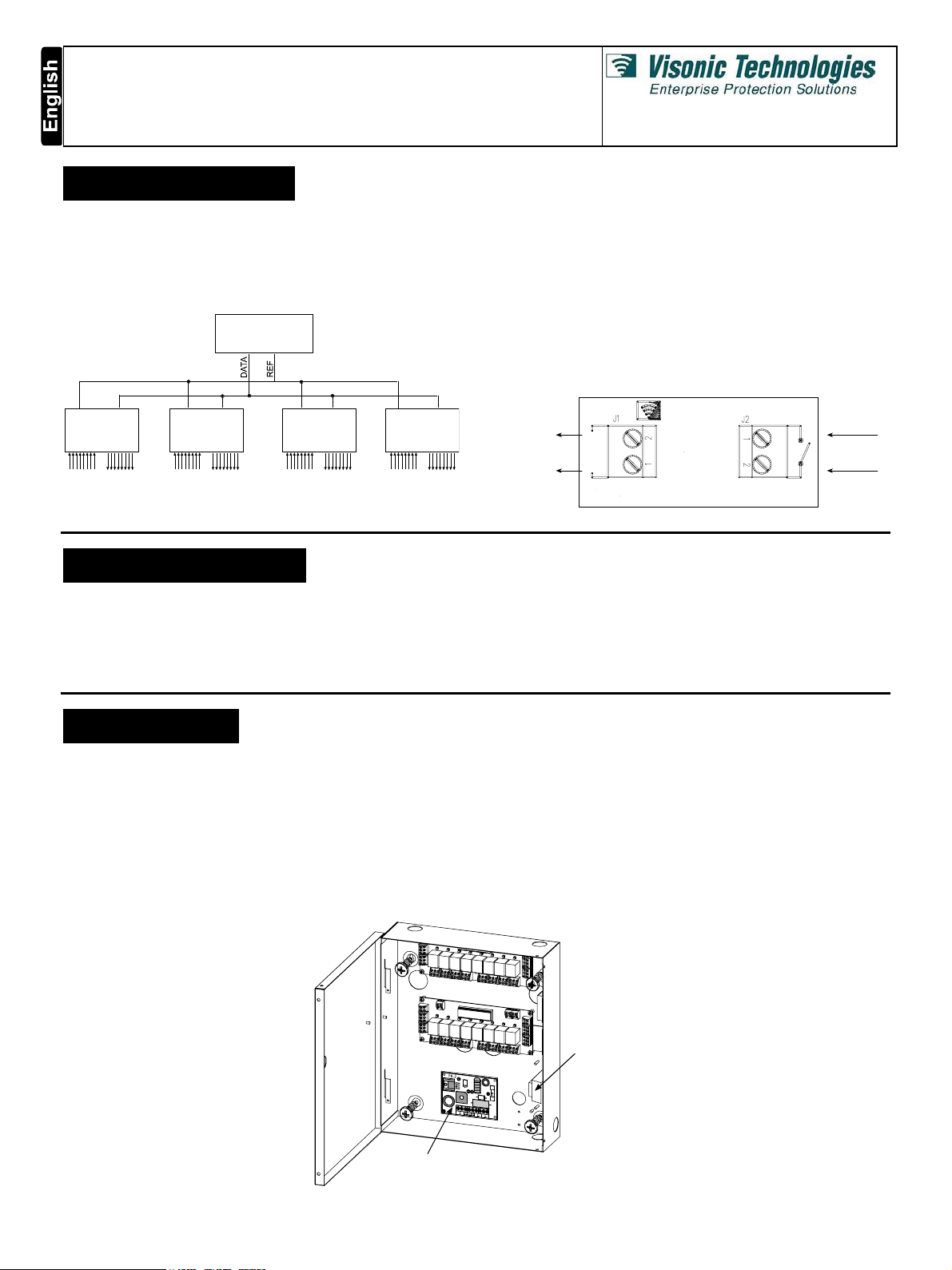
The IOX-4 is an input / output expander for the AXS-100 access
control panel. It contains eight analog inputs and eight dry contact
relays output.
Up to four IOX-4 boards may be connected to each AXS-100
control panel, for a maximum of 32 inputs and 32 outputs for
each controller. All functionality programming is done from the
control panel.
AXS-100
Installation Instructions
The IOX-4 may be used for various purposes:
• Elevator control – up to 32 floors
• Event reporting to an alarm system –event types are separated
into eight groups of which seven control relays on IOX-4 #4.
• Energy management
• Counting inputs up/down
• Emergency operation of doors
Connection of an input device to an IOX-4 input should be done
via an input adapter (8 input adapters are supplied) as shown in
Figure 2. The input adapter includes an EOL termination resistor.
IOX-4
No. 1
(*) (**) (*) (**) (*) (**) (*) (**)
(*) 8 analog inputs
(**) 8 outputs (relays)
Figure 1 - Simplified Interconnection Block Diagram
IOX-4
No. 2
IOX-4
No. 3
IOX-4
No. 4
2. SPECIFICATIONS
ELECTRICAL:
Number of analog inputs: 8
Number of outputs (relays): 8 (N.C. & N.O.), 30VDC, 2A max.
Maximum IOX-4 units for each controller: 4 (for 32 inputs and
32 outputs)
IOX-4 Power Input, from PS-1 DC P.S.: 12 VDC, 0.5A
3. MOUNTING
It is recommended to install the IOX-4 in a Visonic Networks
EXT-100 lockable metal box, Cat. No. 3-6278-0 (not supplied with
the IOX-4.). It is possible to use another box but in this case the
Visonic Networks warranty, will not be valid.
EXT-100 Power Input, from AC Transformer: 14-16.5 VAC, 0.5A
EXT-100 (with two IOX-4 units) Power Input, from AC
Transformer: 14-16.5 VAC, 1A
Place the EXT-100 metal box on the wall, mark 4 screw
locations, drill and fasten the box to the mounting surface
by using 4 screws. Then fasten each IOX-4 board to the
metal box by using 4 screws.
IOX-4 IN
IOX-4 GND
Figure 2 - IOX-4 Input Adapter (End Of Line Termination P.C.B.)
ENVIRONMENTAL:
Operating Temperature: -20°C to 50°C (-4°F to 122°F)
Storage Temperature: -20°C to 50°C (-4°F to 122°F)
PHYSICAL
Dimensions
Weight: 222 g (8 oz)
An example of mounting the IOX-4 in the EXT-100 box (up to two
units) is shown in figure 3.
The EXT-100 box is supplied with a 50VA transformer and a
12 VDC, 1A power supply module.
(L x W x D): 180 x 85 x 22 mm (7-1/16x3-3/8x13/16in)
FROM INPUT
DEVICE
TRANSFORMER
PS-1 POWER SUPPLY
MODULE
Figure 3 - Mounting Two IOX-4 PCBs in EXT-100 Box
DE6314 1
Page 2
4. WIRING
TO N.O.
INPUT DEVICE
E.O.L. PCB
(INPUT ADAPTER)
IOX-4
12V
5V
12VDC INPUT
(SEE NOTE)
IOX-4 address settings
IOX-4 #1
IOX-4 #2
IOX-4 #3
IOX-4 #4
-
+
NOTE: UP TO 2 IOX-4
BOARDS CAN BE
POWERED FROM
THE AXS-100 (PWR
& GND TERMINALS).
CONNECTING 3 OR
4 BOARDS REQUIRES
USING AN EXTERNAL
POWER SUPPLY 12 VDC
FROM EXT-100 PS-1
MODULE
IOX-4
control panel
TB3
(SEE NOTE)
AXS-100
12V
5V
Every relay has
an LED above it
that lights
whenever the
relay is energized .
The relay
energizing
periods are
predefined during
the programming
process.
Note
12V
5V
in1
gnd
in2
in3
relay relay relay relay relay relay relay relay
gnd
in4
RL1 RL2 RL3 RL4 RL5 RL6 RL7 RL8
12VDC INPUT
(SEE NOTE)
-
+
IOX-4
in1
gnd
in2
in3
relay relay relay relay relay relay relayrelay
gnd
in4
RL1 RL2 RL3 RL4 RL5 RL6 RL7 RL8
Figure 4 - IOX-4 Connection Diagram
in5
gnd
in6
in7
gnd
in8
OUTPUTSOUTPUTSOUTPUTSOUTPUTSOUTPUTSOUTPUTSOUTPUT SOUTPUTS
12V
NOTE: IT IS
5V
RECOMMENDED TO
USE TWISTED PAIR
CABLES
in5
gnd
in6
in7
gnd
in8
OUTPUTSOUTPUTSOUTPUTSOUTPUTSOUTPUTSOUTPUTSOUTPUT SOUTPUTS
5. SETUP
5.1 Setting Up the IOX-4 Board
The IOX-4 is connected to the AXS-100 via two or four wires. If
one or two IOX-4 boards are connected to the AXS-100, power
for operating the boards may be drawn from the AXS-100.
Connecting three or four boards requires using an external power
supply.
The IOX-4 has a four-position DIP-switch for setting the board
address.
Each input device has to have an EOL PCB input adapter connected
next to it (see figure 4). The IOX-4 is supplied with 8 modulars.
Inputs and outputs #1 through #8 are on IOX-4 #1.
Inputs and outputs #9 through #16 on IOX-4 #2.
Inputs and outputs #17 through #24 on IOX-4 #3.
Inputs and outputs #25 through #32 on IOX-4 #4.
2 DE6314
Steps:
1. Connect DAT and REF terminals between AXS-100 TB3 and
IOX-4. If less than 3 IOX-4 boards connected, you may also
connect power from AXS TB3.
2. If more than one IOX-4 is to be connected, you will need to
connect the wires in parallel between IOX-4 #1 to#2, etc.
3. Connect input devices to input terminal blocks as shown in
Figure 4.
4. Connect dry contact outputs to relay terminal blocks as shown
in Figure 4.
5. Program input functionality in controller setup (SETUP / INPUT
SETUP).
The AXS-100 controller does not poll IOX-4 boards unless instructed
to. SETUP FLAGS 5 in LOCAL SETUP contains 4 flags (see AXS100 User's Guide, Para. 5.2.5). Flags 1 to 4 represent the IOX #. For
example: If flag #1 is set to ON, the AXS-100 controller will enable
IOX board 1. If flag #3 is set to ON, the AXS-100 controller will
enable IOX board 3, etc.
Page 3

5.2. Programming Input Functionality
M
M
M
M
The AXS-100 allows programming input functionality through the
INPUT SETUP selection in the SETUP menu.
Each input can be programmed to operate in one of the modes of
the IOX-4:
Disabled Input is disabled
Timer Output 1 is controlled by timer
Allow Entry Allow entry through door 1 or 2 of controller
Open All Open all doors in loop while input active
Control
Reader
Counter Up/down count events
Output Output to relay
Each input can be in one of four states:
Idle The sensing device is present and in idle mode.
Active The sensing device is in active mode (triggered).
Short There is a short on the line.
Cut There is a cut on the line – no device detected.
All enabled inputs will cause a trouble event to be generated if a
short or a cut is detected on their line, and a trouble restored
event when the short or cut goes away. A transition from normal
to active or from active to normal will be reported for OUTPUT
mode. In case of OUTPUT mode, generating an event is
dependent on programming.
An enabled input can be responsive all the time or controlled by
one or two devices, both physical and logical. Table #1 lists all
control devices and their numbers. An input device controlled by
another device will cause an action to be taken only if controlling
devices are active.
Each input device has an optional secondary output relay, which is
controlled in one of two modes with disregard to control devices’
status. To select a secondary output relay, set its number in
OUTPUT 2 screen. The secondary relay can be triggered for
amount of time defined in OUT TIME 2 screen if MODE is set to 1.
If mode is set to 2, the relay will be operated in toggle mode.
0 No control device
1 .. 36 Physical input device (1..8 on IOX-4 #1, 25..32 on
Enable/disable reader 1 or 2 or both readers of
controller
It can be normally open or normally closed.
Table #1: Control I/O device addresses
The next two screens allow you to select controlling devices for
this input (see table #1 above for device numbers). If you do not
want to select a device, simply enter zero as its number.
CONTR OL L E D B Y
0
Press Enter to continue.
Enter output number (may be lock number or reader number as
defined in the modes below).
OUTPU T
1
Press Enter to continue.
Set output time for relay output.
OUT T I
E
10
Press Enter to continue.
If you would like to set the independent auxiliary output, enter its
number.
OUTPU T 2
20
Press Enter to continue.
If auxiliary output number is not zero, the following screens will
appear.
The mode for the auxiliary output can be 1 for pulse or 2 for toggle.
ODE
1
Press Enter to continue.
Set output time for auxiliary relay output.
OUT T I
E
10
Press Enter to continue.
Note: To reset all IOX-4 outputs, enter the INPUT SETUP mode,
and when asked by the controller for the input number, press the
UP arrow key (see Figure 5). Then, press Enter continuously until
you return to INPUT SETUP.
ENTER PASSWORD
XXXX
EnterEnter
rEnte
#4, 33..36 on-board)
40 .. 99 Key up/down counter
224 .. 255 Output relay condition. These outputs are used
only for activating alarm relays and to receive
The d isplay w ill be:
SET UP
EDIT KEY S
events. To activate an alarm relay or to receive an
event, add 128 to the output number found in the
register.
225 .. 255 These outputs are used only to receive events and
to activate the controller alarm relay
LOCK SETUP
INPUT SETUP
Enter
SELECT
INPUT #
Note: If you want to receive an event and to activate the alarm
relay, add 128 to the output number.
The programming for each mode varies slightly.
The following screens show the programming of the input device.
Enter Enter Ent er
Enter Enter
First select which input device you would like to program.
S
E L E C T
I N P U T 1
Type input number followed by Enter.
Select input mode by pressing the up and down arrow keys
followed by Enter.
I N P U T
OD E
INPUT SETUP
PASSWORDS
Esc Esc
Figure 5 - INPUT SETUP Mode
OU T P U T
Select input polarity (normally open or normally closed).
P OL A R I T Y
N O
Press 1 for normally closed and 0 for normally open. Press Enter
to continue.
DE6314 3
Page 4

Using Flag Set#2, Flag 5, to Activate to IOX-4 Relays
In Setup→Local Setup menu, it is possible to activate IOX-4 relay
numbers 25 to 32 depending on event type, as follows:
Relay 26 - Valid key indication.
Relay 27 - Unknown key indication.
Relay 28 - Alarm conditions.
Relay 29 - Trouble conditions.
Relay 30 - Long read indication.
Relay 31 - Arm/disarm alarm system.
Relay 32 - Valid key failed to open
5.3 Elevator Control
The Elevator Control function enables authorized people to use
an elevator, up and down, to the desired predefined floors.
AXS-100,
of up to 32 floor buttons in an elevator, for every authorized user.
For this purpose, connect up to 8 floor buttons to the relay
outputs 1 through 8 of each IOX-4 expander. In this way, four
IOX-4 expanders provide control of up to 32 floor buttons.
Inside the elevator, the user presents his tag/card to the proximity
reader. If the tag/card is recognized as a valid one, certain
predefined elevator floor buttons will be active for a predefined
period (see AXS-100 user guide, par. 5.2.6). During this period,
the user should press the desired floor button. If the user presses
a floor button after this period, the button is not active.
To allocate authorized floors (doors) for any user, perform "Add
Key" / “Modify Key” programming, as detailed in the AXS-100 user
guide, par. 3.3.1 and 3.3.5. For example, to allocate floors 2, 8, 16,
20, 25 and 30 to a specific user (key), define doors 2, 8 and G in
“Valid Doors 1” and define doors 4, 9 and E in “Valid Doors 2”.
When the controller operates in toggle mode or time zone
function and soft valid tag is defined and the trigger is set to ON,
all the doors will open and when the trigger is set to OFF all the
doors will close.
Note: In Elevator Control mode, flag set #2, flag 5 must be in
OFF position.
with four IOX-4 expanders, enables / disables the function
5.4 Input Operation Modes
The following sections describe the input modes.
A. Input Disabled
This input is disabled and will cause no action to be taken.
B. Allow Entry
The input will cause left side or right side lock of the controller to
be unlocked for the predefined amount of time. The OUTPUT
number should be 1 or 2 respectively.
Note: Do not operate the input when unlock time operates in
toggle mode (0 seconds).
C. Open All
When the controller operates in toggle mode, or when time zone
function is defined as function 2 (first valid Tag) and the door is in
open state. If trigger is set to ON, all the doors are open; and if
trigger is set to OFF, all the doors are closed.
When the input is in this mode and it goes active, it will make ALL
door locks in this loop to open until the input goes back to normal.
This should be used for fire emergencies.
The OUTPUT number is not important.
Note: It is recommended, in this mode, not to use more than one
input for each loop.
D. Control Reader
The input will cause left side or right side or both readers of the
controller to be enabled or disabled according to its state. The
OUTPUT number should be 1, 2 or 3 respectively. Data Register
3 has to be set to 65535 to enable this feature (see “EDIT
REGISTERS” in AXS-100 programming manual).
Note: When completing the task in Control Reader mode,
change the value of the register #3 to 0.
E. Counter
The AXS-100 can use an input for counting events expressed as
pulses on any of the inputs. The counting is done in data registers
40 to 99. The OUTPUT number should reflect which data register is
to be used. More than one input can affect a counting data register.
Each input setup can be configured to count up and/or down. This
facilitates the ability to count up using one input and count down
using another input. The OUT TIME number should be 1 for upcount, 2 for down-count and 3 for both up and down count (when
pressed counting is upward; when released counting is downward).
Note: If the value of the up/down counter (40 to 99) =0, the
controller will not count downwards.
F. Output
An input may be used to control an output relay on the IOX-4
boards. The OUTPUT number defines which output relay is to be
controlled (1 through 32). Adding 64 to relay number will cause
input to operate the relay in toggle mode. Adding 128 to relay
number will cause the input triggering and restoring to generate
an event message. Set the OUT TIME number to amount of time
in seconds to operate the relay (1 through 2000 seconds).
G. Timer
1. OUTPUT 1 is controlled by the timer. OUT TIME 1 is the period
of time that the counter counts from 1 second to 2000 seconds.
2. To operate OUTPUT 1, press down on the INPUT at every
counting period. After counting is completed, the OUTPUT is
functional.
3. To receive an event, add the number 128 to the OUTPUT
number. The received event is the INPUT TRIGGER.
5.5 Using Relay Outputs Without Inputs
The IOX-4 relay outputs can be used with no input functionality.
The following functions can be enabled by setting flags in LOCAL
SETUP:
Event group type output Set flag 5 in SETUP FLAGS 2.
Elevator control Set controller operating mode to 9 in
Note: In the IOX-4, relay 25 will be activated each time a tag is
presented to the reader when KEY FLAG 7 of the tag is set to
ON. This has no relevance to FLAG 5 in SETUP FLAGS 2, (see
AXS-100 User Guide Para. 3.3.2 Modify Key Flags).
LOCAL SETUP.
6. TESTING
After mounting and wiring, the IOX-4 should be tested. Activate
the unit inputs and verify proper operation according to the
application used.
WARNING! Changes or modifications to this unit not expressly approved by the party responsible for compliance could void the user's
authority to operate the equipment.
4 DE6314
It is recommended to perform a periodical test once a week such as presenting a tag to the reader and verifying that the
relevant door is opened.
No maintenance is required for the IOX-4 unit.
Page 5

W
ARRANTY
Visonic Technologies Ltd. and/or its subsidiaries and its affiliates ("the Manufacturer")
warrants its products hereinafter referred to as "the Product" or "Products" to be in
conformance with its own plans and specifications and to be free of defects in materials and
workmanship under normal use and service for a period of twelve months from the date of
shipment by the Manufacturer. The Manufacturer's obligations shall be limited within the
warranty period, at its option, to repair or replace the product or any part thereof. The
Manufacturer shall not be responsible for dismantling and/or reinstallation charges. To
exercise the warranty the product must be returned to the Manufacturer freight prepaid and
insured.
This warranty does not apply in the following cases: improper installation, misuse,
failure to follow installation and operating instructions, alteration, abuse, accident or
tampering, and repair by anyone other than the Manufacturer.
This warranty is exclusive and expressly in lieu of all other warranties, obligations or
liabilities, whether written, oral, express or implied, including any warranty of
merchantability or fitness for a particular purpose, or otherwise. In no case shall the
Manufacturer be liable to anyone for any consequential or incidental damages for breach
of this warranty or any other warranties whatsoever, as aforesaid.
This warranty shall not be modified, varied or extended, and the Manufacturer does not
authorize any person to act on its behalf in the modification, variation or extension of this
warranty. This warranty shall apply to the Product only. All products, accessories or
attachments of others used in conjunction with the Product, including batteries, shall be
covered solely by their own warranty, if any. The Manufacturer shall not be liable for any
damage or loss whatsoever, whether directly, indirectly, incidentally, consequentially or
otherwise, caused by the malfunction of the Product due to products, accessories, or
attachments of others, including batteries, used in conjunction with the Products.
The Manufacturer does not represent that its Product may not be compromised and/or
circumvented, or that the Product will prevent any death, personal and/or bodily injury
and/or damage to property resulting from burglary, robbery, fire or otherwise, or that the
Product will in all cases provide adequate warning or protection. User understands that a
properly installed and maintained alarm may only reduce the risk of events such as
burglary, robbery, and fire without warning, but it is not insurance or a guarantee that
such will not occur or that there will be no death, personal damage and/or damage to
property as a result.
The Manufacturer shall have no liability for any death, personal and/or bodily injury
and/or damage to property or other loss whether direct, indirect, incidental,
consequential or otherwise, based on a claim that the Product failed to function.
However, if the Manufacturer is held liable, whether directly or indirectly, for any loss or
damage arising under this limited warranty or otherwise, regardless of cause or origin, the
Manufacturer's maximum liability shall not in any case exceed the purchase price of the
Product, which shall be fixed as liquidated damages and not as a penalty, and shall be
the complete and exclusive remedy against the Manufacturer.
Warning: The user should follow the installation and operation instructions and among
other things test the Product and the whole system at least once a week. For various
reasons, including, but not limited to, changes in environmental conditions, electric or
electronic disruptions and tampering, the Product may not perform as expected. The user
is advised to take all necessary precautions for his /her safety and the protection of
his/her property.
6/91
VISONIC TECHNOLOGIES. (ISRAEL): 30 Habarzel St. Tel Aviv 69710 ISRAEL Tel 972-3-7681400 Fax: 972-3-7681415 E-MAIL: support@visonictech.com
VTA (VISONIC TECHNOLOGIES AMERICAS): 65 West Dudley Town Road, Bloomfield CT. 06002-1911 USA. TEL.: (860) 243 0833, (800) 223 0020
FAX: (860) 242-8094. E-MAIL: usa_support@visonic.com
VT UK (VISONIC TECHNOLOGIES UK): Fraser Road, Priory Business Park, Bedford MK44 3WH ENGLAND. TEL.: 44-870-730-0840; FAX: 44-870-730-0839
INTERNET: www.visonictech.com
VISONIC TECHNOLOGIES LTD. 2004 IOX-4 DE6314- (REV. 3, 08/03)
DE6314 5
 Loading...