

Page 1
DE1220 1
HUNTER
HUNTERHUNTER
HUNTER
Anti-Masking, Self-Testing PIR Motion Detector
Installation Instructions
1111. INTRODUCTION
. INTRODUCTION. INTRODUCTION
. INTRODUCTION
The HUNTER is a sophisticated PIR that utilizes an advanced
motion analysis algorithm, the latest anti-masking technology and
motion simulation self-test routines.
The advanced motion analysis algorithm - True Motion
Recognition™ - provides improved distinction between true
motion of a human body and any other disturbance that would
cause other detectors to produce false alarms.
Masking and/or internal circuit malfunction cause trouble
indications to appear: the green LED flashes and the TRB
(trouble) relay drops out. At power up, a unique software routine
adapts the detector to its immediate surroundings. Despite this, if
an object is too close to the lens or the field of view is too narrow,
the detector will respond as it does upon masking.
The HUNTER includes temperature compensation circuits - for
maximum catch performance and optimum protection from false
alarms. A built-in motion event verification counter can be
programmed to trigger an alarm as a result of 1 or 2 consecutive
motion events, depending on the detection sensitivity required.
A “TEST” (T) input permits switching the detector to the walk-test
mode and back without removing the front cover. The test input
polarity can be selected with a DIP switch (see Para. 3.6).
Long-term stability and high reliability are assured by a special
self-adapting algorithm, that continuously compensates for
environmental changes. The entire electronic circuitry is enclosed
in a protective sealed module, with the sensor element practically
isolated from gusts of wind and insects.
2222.
. .
. SPECIFICATIONS
GENERAL
Sensor Type: Low-noise dual-element pyroelectric unit.
Alarm Relay: N.C. contacts with 18-ohm resistor in series;
contacts rated at 0.1 A resistive / 30 VDC
Alarm Period: 2-3 seconds minimum
Tamper Switch: N.C. contacts, 50 mA resistive / 30 VDC
TRB Relay: N.C. contacts with 18-ohm resistor in series;
contacts rated at 0.1 A resistive / 30 VDC
True Motion Event Verification Counter: 1 or 2 events
Masking Detection Delay: 30 seconds
POWER SUPPLY
Input Voltage: 9 - 16 VDC
Standby Current Drain: 17 mA @ 12 VDC
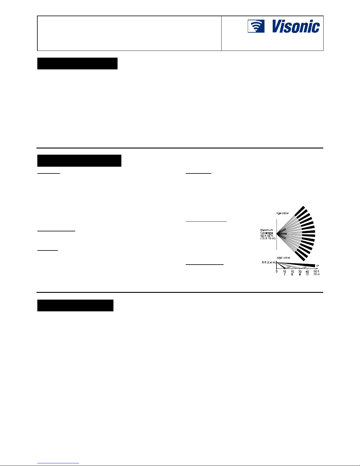
OPTICAL
Lens Type: 90° (wide angle), 34 beams in 3 detection layers.
Coverage Area: 15 x 15 m (50 x 50 ft).
Adjustment:
Vertical: 0° to - 12° with built-in calibrated scale.
Horizontal: ±7.5° by shifting the lens left or right in the front
window (greater shift is possible with optional swivel brackets).
MOUNTING
Configurations: Surface or corner (without swivel brackets)
Height: Up to 3.6 m (12 ft)
Optional Accessories: BR-1: Swivel bracket for surface
mounting, adjustable 30° downward and 45° left, 45° right.
BR-2: BR-1 with corner mounting adapter.
BR-3: BR-1 with ceiling
mounting adapter.
ENVIRONMENTAL
Operating Temperatures:
-10° to 50°C (14° to 122°F)
Storage Temperatures:
-20° to 60°C (-4° to 140°F)
RFI protection: Greater than
20 V/m up to 1000 MHz.
PHYSICAL DATA
Dimensions (H x W x D):
116 x 60 x 45 mm
(4-9/16 x 2-3/8 x 1-3/4 in.)
Weight: 112 g (4 oz)
3. INSTALLATION
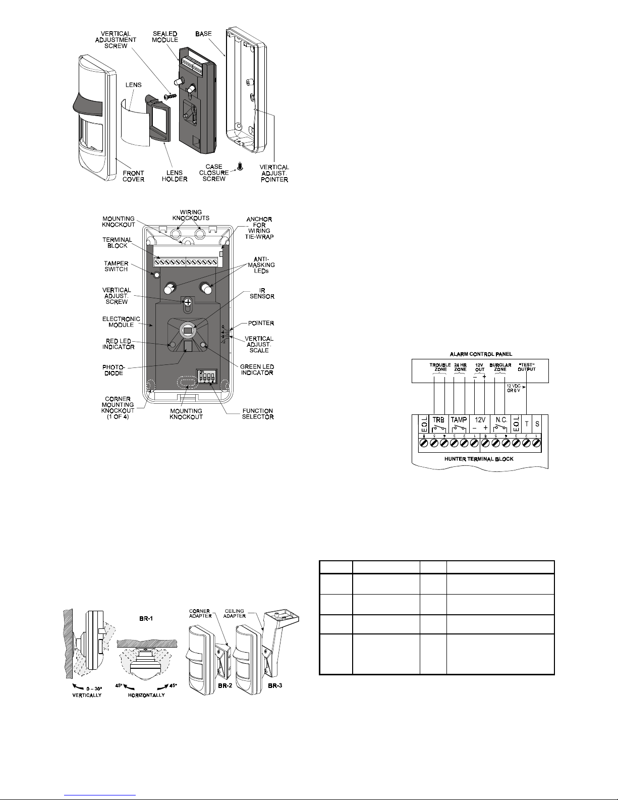
3.1 Construction Details
The electronic circuitry is enclosed in a sealed module, attached
to the base with a single screw (see Figure 2).
The electronic module may be shifted up or down along the base
for vertical adjustment of the detection beam angle.
The front cover accommodates the Fresnel lens, that can be
unfastened for horizontal adjustment or for replacement. The LEDs,
which are positioned behind the lens, are visible when illuminated.
3.2 Selecting the Mounting Location
Always mount the detector unit on a firm and stable surface.
A. Select the mounting location so that the expected motion of an
intruder would cross the beams of the coverage pattern.
B. Avoid aiming the detector at heaters, sources of bright light
and windows that are subject to direct sunlight. Also avoid
running the wiring close to high-power electrical cables.
C. Make sure not to install the unit where obstacles are present
0.5 meter (1.5 ft) away from the lens or closer.
3.3 Mounting
A . Remove the screw located at the bottom and then take the
front cover off (see Figure 2).
B . Remove the vertical adjustment screw and detach the module
from the base.
C . Mount the base (with the wiring entry knockouts up) in the
location and height selected for optimum coverage. For
surface mounting, use the two knockouts at the back of the
base. For corner mounting, use the knockouts on the angled
sides (see Figure 3).
Figure 1. Coverage Pattern
Page 2
2 DE1220
Figure 2. Exploded View of the HUNTER
Figure 3. HUNTER as Viewed with Cover Removed
D. Put the electronic module back in place and remount the
vertical adjustment screw (but do not tighten it fully yet).
E. Set the DIP switch function selector as required for the
particular application (see Paragraph 3.6 for details).
F. Carry out the necessary wiring operations as outlined in
Paragraph 3.5).
3.4 Optional Swivel Brackets
Three optional swivel brackets are available. They are intended to
enhance the flexibility of installation. Each bracket comes
complete with detailed installation instructions in its own packing
box.
BR-1 - a surface-mounted swivel bracket (see Fig. 4).
BR-2 - corner mounting swivel bracket (see Fig. 5).
BR-3 - ceiling mounting bracket (see Fig. 5).
Attention! With swivel brackets in use, the effective detection
range may differ from that indicated in Table 2.
Fig. 4. Hunter with BR-1 Fig. 5. Hunter with BR-2 / BR-3
3.5 Wiring
A. Terminal Assignments
N.C. relay output:
The normally closed alarm relay contacts open upon detection of
motion (alarm) or during a power failure.
TAMP (tamper output): The TAMP (tamper) contacts, which are
normally closed, open when the unit’s front cover is removed.
TRB (trouble) Relay: The normally closed trouble relay contacts
open when masking is sensed or when trouble is detected by the
unit’s self test circuitry.
T (TEST) input: Used to remotely switch the detector into the
walk-test mode and back to normal, by applying +12 VDC or 0
VDC to this terminal (see SW-4 in Para. 3.6).
E.O.L. terminals: The two “floating” E.O.L. terminals serve only
as connection points for E.O.L. (end-of-line) resistors.
B. Wiring Procedure
Refer to Figure 6 and use #22 AWG or larger conductors to wire
the detector as follows:
(1) Connect one N.C. output terminals of the detector to a burglar
zone terminals of the alarm control panel.
(2) Connect the detector’s TAMP terminals across the terminals
of a 24-hour zone of the alarm control panel.
Note: If the control panel is set for E.O.L. and you are wiring the
most distant detector in the loop, use the closest E.O.L. terminal
to connect the required E.O.L. resistor in series with the loop.
( 3 ) Connect the detector’s TRB relay terminals across the
terminals of a 24-hour trouble zone of the control panel.
( 4 ) Connect a single wire between the detector’s T terminal and
the walk-test control voltage source (see Para. 3.6 for TEST
input polarity).
( 5 ) Connect the 12 V
(+) and (–)
terminals to a 9 16 VDC power
source and check
for correct polarity.
The power supply
must have
at
least
4
hours of battery
backup.
The
standby current
consumption
of
each detector unit
is about 17 mA.
Figure 6. Terminal Block Wiring
3.6 The Function Switches
A. Switch Tasks
The HUNTER is equipped with a 4-position DIP switch function
selector (see Fig. 3).
Table 1. Setting the Function Selector
Switch Function Pos. Selected Option
SW-1
Motion event
Counter
ON
OFF
2 motion events to alarm
1 motion event to alarm
SW-2
LED control ON
OFF
Both LEDs are enabled
Both LEDs are disabled
SW-3
Reset after trouble - Resets the unit when switched
from OFF to ON or ON to OFF
SW-4
Selects the TEST
(“T”) input signal
polarity
ON
OFF
0 V disables walk test
+12 VDC enables walk test*
+12 VDC disables walk test*
0 V enables walk test*
* +12 VDC or open circuit.
Note: OFF is not effective in the walk test mode and during the
power-up adaptation period.
Page 3

DE1220 3
B. Setting the Switches
Set the function switches as desired prior to applying power. The
ON position is indicated on the switch body.
SWITCH SW-1:
If you set this switch to OFF (1 motion event),
the detector’s sensitivity will be increased, and if you set this
switch set to ON (2 motion events), you will get the highest
immunity against false alarms.
SWITCH SW-2: You may enable or disable the LED walk-test
indicators. However, even if disabled, they will be automatically
enabled when the detector is switched to the test mode.
SWITCH SW-3
Resetting after trouble - it makes no difference whether the lever
is switched from OFF to ON or vice versa.
SWITCH SW-4: Set this switch in accordance with the control
panel’s TEST output. If there is no such output, simply wire the
control panel’s 0 VDC (ground) to the detector’s “T” terminal
through a TEST switch installed at a convenient location.
Set SW-4 to OFF if you do not intend to use the T input.
3.7 Vertical Pattern Adjustment
To adjust the vertical pattern, loosen the vertical adjustment
screw slightly and slide the electronic module up or down to the
desired angle. Adjust the scale according to Table 2 for the
desired mounting height and coverage range. Once the module is
aligned correctly, tighten the screw firmly.
Table 2. Vertical Adjustment Chart
3.8 Horizontal Pattern Adjustment
The coverage pattern may be
adjusted ±7.5° by shifting the lens
off its centered position:
A . Remove the lens holder as
shown in Figure 7.
B . Shift the lens in the desired
direction (right or left).
C . Hold the lens in position and
re-insert the lens holder bottom end first. Next, push
the top end against the front
cover until the lens holder
snaps into place.
Figure 7. Releasing the Lens
4. OPERATION AND TESTING
4.1 Output Circuit Behavior
A. Alarm Relay
When an alarm occurs, the alarm relay contacts open for 2-3
seconds.
B. TRB Relay
The TRB relay drops out (its contacts open) whenever masking is
detected, or upon detection of an internal malfunction by
automatic self test routine. The relay pulls in as soon as the
cause for trouble is removed.
4.2 LED Display
Two LEDs, red and green, convey status information by various
signaling combi- nations, as detailed in Table 3 below. However,
the following rules must be taken into account:
A. The LED indicators may be enabled by setting DIP switch
SW-2 to ON or applying “test enable” voltage to the “T”
terminal. While being enabled by one, the LEDs can not be
disabled by the other.
B. Even if the LEDs are disabled, they will still function
throughout the 2-minute power-up adaptation period and as
trouble indicators.
Table 3. LED Displays
State of
RED LED
State of
GREEN LED
Interpretation
Flashing Flashing Adaptation period (about 2 minutes)
upon power up.
OFF OFF Ready to detect. There are presently
no alarm/trouble events.
ON (2-3 s) N/A Motion is being detected.
N/A Flashing Masking or internal failure state.
4.3 Resetting after Trouble
Flashing of the green LED indicates that masking or internal
circuit trouble are being sensed. While the green LED flashes,
the TRB relay contacts are open.
To determine the cause for trouble, check for masking:
• Foreign material may be glued to the lens or sprayed on it.
• An object may have been placed less than 0.5 m (1.5 ft) away
from the detector.
• An object situated in the detector’s field of view less than 0.5 m
(1.5 ft) from the detector has been re-located (the detector
“considers” this change in its surroundings as a masking event).
Note: Erratic behavior of the detector may result from partial
masking - check the lens very carefully.
Remove masking if found. Then remove the cover, change the
position of DIP switch SW-3 (from OFF to ON or vice versa),
mount the cover quickly in place and get away from the detector.
IMPORTANT! Changing the position of SW-3 resets the
detector and causes it to re-adapt to its current surroundings for
2-minutes. Stay at least 0.5 m (1.5 ft) away from the detector,
so as not to disrupt this process. The green and red LED will
flash alternately until the 2 minute period is up. If they continue
to flash, check again for masking.
Reset is also possible without removing the cover - apply the “test
enable” voltage to the “T” terminal (see Para. 3.6) and conduct a
short walk test, causing the detector to alarm at least 3 times.
After reset, the detector should function normally - the green LED
should not flash and the TRB relay contacts should close. If this
is not so, and masking has been ruled out, the trouble indication
is probably due to internal circuit trouble. The only remedy for this
is replacing the detector unit with a new one.
4.4 Testing procedure
A. Set SW-2 to ON, or leave it OFF but apply the “test enable”
voltage to the “T” terminal. Remount the detector’s cover.
B. Power up the system. The red and green LEDs will flash
alternately, indicating that the detector is adapting itself to its
present surroundings. Stay at least 0.5 m (1.5 ft) away from
the detector, until the 2-minute startup period ends (until
the LEDs stop flashing alternately).
Page 4

4 DE1220
C. Enter the detector’s field of view and walk test the entire
coverage area, while observing the red LED. The LED will
light for 2-3 seconds each time your motion is detected.
D. Tape a piece of cardboard to the detector’s front to
deliberately mask the lens. After 30 seconds, the green LED
should start flashing, and the trouble zone of the control panel
should go into alarm (the TRB relay drops out).
E. Remove the masking from the detector’s front. The green LED
should extinguish (after a few seconds).
F. Apply the desired voltage to the “T” terminal, or set SW-2 as
desired to enable/disable the LEDs. The detector is ready for
use.
WARRANTY
WARRANTYWARRANTY
WARRANTY
Visonic Ltd. and/or its subsidiaries and its affiliates ("the Manufacturer") warrants its
products hereinafter referred to as "the Product" or "Products" to be in conformance with
its own plans and specifications and to be free of defects in materials and workmanship
under normal use and service for a period of twelve months from the date of shipment by
the Manufacturer. The Manufacturer's obligations shall be limited within the warranty
period, at its option, to repair or replace the product or any part thereof. The Manufacturer
shall not be responsible for dismantling and/or reinstallation charges. To exercise the
warranty the product must be returned to the Manufacturer freight prepaid and insured.
This warranty does not apply in the following cases: improper installation, misuse,
failure to follow installation and operating instructions, alteration, abuse, accident or
tampering, and repair by anyone other than the Manufacturer.
This warranty is exclusive and expressly in lieu of all other warranties, obligations or
liabilities, whether written, oral, express or implied, including any warranty of
merchantability or fitness for a particular purpose, or otherwise. In no case shall the
Manufacturer be liable to anyone for any consequential or incidental damages for breach
of this warranty or any other warranties whatsoever, as aforesaid.
This warranty shall not be modified, varied or extended, and the Manufacturer does not
authorize any person to act on its behalf in the modification, variation or extension of this
warranty. This warranty shall apply to the Product only. All products, accessories or
attachments of others used in conjunction with the Product, including batteries, shall be
covered solely by their own warranty, if any. The Manufacturer shall not be liable for any
damage or loss whatsoever, whether directly, indirectly, incidentally, consequentially or
otherwise, caused by the malfunction of the Product due to products, accessories, or
attachments of others, including batteries, used in conjunction with the Products.
The Manufacturer does not represent that its Product may not be compromised and/or
circumvented, or that the Product will prevent any death, personal and/or bodily injury
and/or damage to property resulting from burglary, robbery, fire or otherwise, or that the
Product will in all cases provide adequate warning or protection. User understands that a
properly installed and maintained alarm may only reduce the risk of events such as
burglary, robbery, and fire without warning, but it is not insurance or a guarantee that such
will not occur or that there will be no death, personal damage and/or damage to property
as a result.
The Manufacturer shall have no liability for any death, personal and/or bodily injury
and/or damage to property or other loss whether direct, indirect, incidental,
consequential or otherwise, based on a claim that the Product failed to function.
However, if the Manufacturer is held liable, whether directly or indirectly, for any loss or
damage arising under this limited warranty or otherwise, regardless of cause or origin, the
Manufacturer's maximum liability shall not in any case exceed the purchase price of the
Product, which shall be fixed as liquidated damages and not as a penalty, and shall be the
complete and exclusive remedy against the Manufacturer.
Warning: The user should follow the installation and operation instructions and among
other things test the Product and the whole system at least once a week. For various
reasons, including, but not limited to, changes in environmental conditions, electric or
electronic disruptions and tampering, the Product may not perform as expected. The user
is advised to take all necessary precautions for his/her safety and the protection of his/her
property.
6/91
VISONIC LTD. (ISRAEL): P.O.B 22020 TEL-AVIV 61220 ISRAEL. PHONE: (972-3) 645-6789, FAX: (972-3) 645-6788
VISONIC INC. (U.S.A.): 10 NORTHWOOD DRIVE, BLOOMFIELD CT. 06002-1911. PHONE: (860) 243-0833, (800) 223-0020 FAX: (860) 242-8094
VISONIC LTD. (UK): FRASER ROAD, PRIORY BUSINESS PARK, BEDFO RD MK44 3WH. PHONE: ( 0870) 7300800 FAX: (0870) 7300801
INTERNET:
www.visonic.com
VISONIC LTD. 2002 HUNTER D-1220-0 NEW: DE1220- (REV. 5, 5/02)
 Loading...