

Page 1

D-303424 GSD-441 PG2 Installation Instructions 1
GSD-441 PG2
PowerG Wireless Natural Gas (Methane) Detector
Installation Instructions
1. INTRODUCTION
The GSD-441 PG2 is a wireless PowerG two-way natural gas
(Methane) detector. The GSD-441 PG2 is a natural gas detector
designed to send an alarm when Methane gas is detected. The
detectors can be used in a house, apartment, caravan, mobile home
or yacht.
The detectors are powered by 220 VAC. An internal Lithium battery
is used for AC power failure reporting only (the battery does not
power the detector).
The detector can send the following messages to the alarm system
control panel: Gas alarm, gas sensor failure, AC power failure and
low battery voltage.
A
B
C
D
A. Test / Mute button
B. Red LED
C. Orange LED
D. Green LED
Figure 1 –
External View
The GSD-441 PG2 is designed for wall mounting and should be
placed in a location where gas presence, for example leakage, is
probable.
Upon gas detection, an audible buzzer is sounded and the built-in
transmitter transmits a digital message, composed of the detector's
PowerG ID followed by status messages. Alarm and other data are
thus forwarded to the alarm system. A periodic supervision
message is transmitted automatically (see specifications) to inform
the alarm system at regular intervals, of the unit’s active
participation in the system.
GSD-441 PG2
A
B
A. Gas leak from gas cooker, boiler room, gas connection
chamber, etc.
B. PowerMaster control panel
Figure 2 – Integration with the Alarm System
2. INSTALLATION
2.1 Preparing the Installation
A. The GSD-441 PG2 gas detector plugs directly into a standard 220VAC household switchable outlet (by a switch or circuit breaker).
Note: The installation must comply with the local authority electrical standards.
B. The ventilation slots must not be blocked and the unit must be kept free of dust.
C. A proper airflow must be maintained through the unit to obtain an air sampling of that area of the house where the sensor is situated.
D. The unit must be installed at least three feet from any gas appliance to eliminate false alarms but should not be placed over
20 feet from such appliances.
E. Install the unit away from any sources of vapor such as alcohol, liquor, vehicle exhaust, hair spray, cleaning agents, deodorants, paint,
fluorocarbons, or industrial solvents because vapors from these substances will trigger false alarms.
F. Do not install the unit directly above cooking appliances, directly above a sink, or adjacent to extractor fans.
Important!
When the alarm sounds, immediately find out the cause and remedy it or evacuate the building
Ventilate the area by opening doors and windows
Immediately extinguish any flames or pilot lights
Do not operate any electrical devices
Determine the source of the gas. Seek a qualified technician or call your local gas company
Page 2
2 D-303424 GSD-441 PG2 Installation Instructions
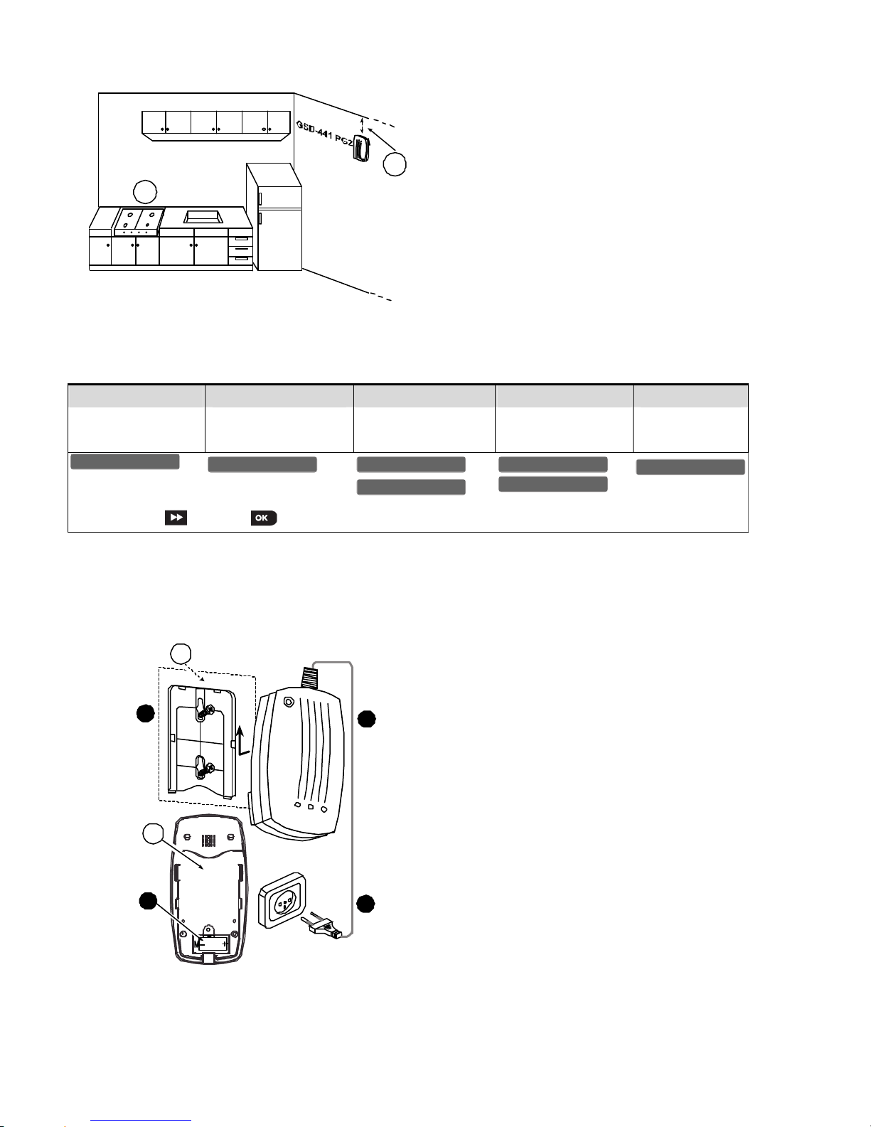
2.2 Installing the GSD-441 PG2
Warning: Installation must be performed by a professional person.
A
B
Figure 3. Alarm System Integration
A. Gas Cooker
B. For Methane gas (CH4) detection, mount the GSD-441 PG2
approx. 30 cm below the ceiling and above the highest
window or door opening.
2.3 Enrollment
Refer to the PowerMaster Installer Guide and follow the procedure under the "02:ZONES/DEVICES" option of the Installer Menu.
A general description of the procedure is provided in the following flow chart.
Step 1 Step 2 Step 3 Step 4 Step 5
Enter the Installer menu
and select
“02:ZONES/DEVICES”
Select "ADD NEW
DEVICE" Option
Enroll the device or Enter
the device ID
See Note
Select the desired Zone
Number
Configure the
Location Parameter
means scroll and select
Note:
i) Insert the battery (see Figure 4) to enroll the gas detector.
-orii) Key in the device ID of the gas detector and at a later stage, when the installation makes possible, insert the battery.
2.4 Inserting Battery
3
1
4
2
B
A
Figure 4 – Installing the GSD-441 PG2
1. Fasten the bracket to the mounting surface with 2 screws.
2. Insert battery (verify proper polarity).
3. Locate the detector on the bracket, and slide it up as shown.
4. Connect to 220VAC
A. Mounting surface
B. Rear side
Caution! Risk of explosion if battery is replaced by an incorrect
type. Dispose of used batteries according to the manufacturer's
instructions.
Z
07.L
OCATION
ID No. 220
-
X
XXX
Z
07:GAS Sensor
E
NTR ID:XXX
-
X
XXX
E
NROLL NOW or
A
DD NEW DEVICES
0
2.ZONES/DEVICES
Page 3

D-303424 GSD-441 PG2 Installation Instructions 3
3. PREPARATION FOR USE
3.1 The LED Functions
Once the unit is plugged into the wall outlet, the green power indicator flashes indicating that power is present and the unit is working. After
an initial ten minute warm-up period, the unit will start the process of continually sampling the air around it.
Table 1. LED functions
LED Function
Green
Flashing: During the first ten minutes (after power connection) the green LED flashes (stabilization time).
Constant light: The equipment is ready for operation: "Power ON".
Orange
Illuminates in the event of trouble and emits a lengthy buzzer sound.
Red (alarm)
Flashes and a supplementary acoustic signal generator (transducer) sounds intermittently in the event of an alarm.
3.2 Test Button and Muting Switch
Press down on the Test / Silent button (see Figure 2) to test the operation of the indicators. The red and orange LEDs will flash and an
acoustic signal tone will sound intermittently. This action should be performed once a week. Use the Test / Silent button (see Figure 2) to
switch off the acoustic alarm tone in the event of an alarm. The red LED will continue to flash and a short signal tone will sound
approximately every 45 seconds.
Note: Do not test the GSD-441 PG2 using a gas lighter.
Note: In the event of a gas leakage, the smell of the gas may be in the air before the detector activates the alarm.
4. MISCELLANEOUS COMMENTS
Visonic Ltd. wireless systems are very reliable and are tested to high standards. However, due to low transmitting power and limited range
(required by FCC and other regulatory authorities), there are some limitations to be considered:
A. Receivers may be blocked by radio signals occurring on or near their operating frequencies, regardless of the digital code used.
B. A receiver responds only to one transmitted signal at a time.
C. Wireless devices should be tested regularly to determine whether there are sources of interference and to protect against faults.
D. It is recommended to unplug the detector from the electricity mains before cleaning. Clean only using a dry cloth. Do not clean using a liquid
substance. Clean externally surfaces only.
The user is cautioned that changes or modifications to the unit, not expressly approved by Visonic Ltd., could void the user’s FCC or other
authority to operate the equipment
.
5. COMPLIANCE WITH STANDARDS
FCC part 15 statement:
The digital circuit of this device has been tested and found to comply with the limits for a Class B digital device, pursuant to part 15 of the
FCC Rules. These limits are designed to provide reasonable protection against harmful interference in a residential installation. This
equipment generates, uses and can radiate radio
frequency energy and, if not installed and used in accordance with the instructions,
may cause harmful interference to radio communications. However, there is no guarantee that interference will not occur in a particular
installation. If this equipment does cause harmful interference to radio or television reception, which can be determined by turning the
equipment off and on, the user is encouraged to try to correct the interference by one or more of the following measures:
-Reorient or relocate the receiving antenna.
-Increase the separation between the equipment and receiver.
-Connect the equipment into an outlet on a circuit different from that to which the receiver is connected.
-Consult the dealer or an experienced radio/TV technician for help.
IC statement:
This device complies with Part 15 of the FCC Rules and with Industry Canada license-exempt RSS standard(s). Operation is subject to the
following two conditions: (1) this device may not cause interference, and (2) this device must accept any interference, including interference
that may cause undesired operation of the device.
Le present appareil est conforme aux CNR d'Industrie Canada applicables aux appareils radio exempts de licence. L'exploitation est
autorisee aux deux conditions suivantes :(1) l'appareil ne doit pas produire de brouillage, et (2) l'utilisateur de l'appareil doit accepter tout
brouillage radioelectrique subi, meme si le brouillage est susceptible d'en compromettre le fonctionnement.
WARNING!
To comply with FCC and IC RF exposure compliance requirements, the device should be located at a distance of at least 20 cm from all
persons during normal operation. The antennas used for this product must not be co-located or operated in conjunction with any other
antenna or transmitter.
Page 4

4 D-303424 GSD-441 PG2 Installation Instructions
APPENDIX: SPECIFICATONS
Gas Type
Methane (CH4)
Audible Signal Volume
At least 85 dB at a distance of 3 m.
Sensitivity
8% 3% of the gas Lower Explosion Limit (LEL).
Supervision
Signaling at 15 minute intervals or according to local standards
Important: The detector will not operate without 220V power connection. In the event of a power
failure or where the detector is not connected to a power source, an AC failure message is sent
to the control panel (will be received by the PowerMaster control panel version 13 and above
only)
ALARM REPORTS
Gas alarm
Every 20 sec. for the first 3 minutes.
Every 3 min. for the next 27 minutes.
Alarm stops after 30 min. or if the detector goes into "alarm restore".
AC failure
20 seconds after an AC failure occurrence, the AC failure will be reported – will be received by
the PowerMaster control panel. The report will be repeated every 20 seconds for 3 minutes.
Trouble message
When gas sensor fails, failure message will be received only the PowerMaster control panel.
Communication Protocol PowerG
Power Source
220-240V 50 Hz
Battery 3V lithium battery, type CR123A, Panasonic, Sanyo or GP.
Battery Life Expectancy 5 years (for typical use, in room temperature)
Operating Temperatures 0°C to 45°C (32°F to 113°F)
Dimensions 155 mm (6-1/8 in.) x 80 mm (3-1/6 in.) x 58 (2-5/16 in.)
Weight (with battery) 370 g (13 oz.)
Compliance with Standards
Meets requirements of EN 50194, EN 60950, EN 61010-1, EN 50270, EN 300220, EN 301489
WARRANTY
Visonic Limited (the “Manufacturer") warrants this product only (the "Product") to the original purchas er only (the
“Purchaser”) against defective workmanship and materials under normal use of the Pr oduct for a period of
twelve (12) months from the date of shipm ent by the Manufacturer.
This Warranty is absolutely condition al upon the Product having been properly installed, maintained and
operated under conditions of normal use in accor dance with the Manufacturers recommended ins tallation and
operation instructions. Products which have become defective for any other reason, accor ding to the
Manufacturers discretion, such as improper installation, failure t o follow recommended installa tion and
operational instructions, neglect, willful damage, misuse or vanda lism, accidental damage, alteration or
tampering, or repair by anyone other than the manufacturer, are not covered b y this Warranty.
The Manufacturer does not represent that this Product may not be compromised and/or circumvented or that the
Product will prevent any death and/or p ersonal injury and/or damage to property resulting from burglary,
robbery, fire or otherwise, or that the Pr oduct will in all cases provide adequate warning or protection. The
Product, properly installed and m aintained, only reduces the risk of such events without warning and it is not a
guarantee or insurance that such events wil l not occur.
THIS WARRANTY IS EXCLUSIVE AND EXPRESSL Y IN LIEU OF ALL OTHER WARRANTIES,
OBLIGATIONS OR LIABILITIES, WHETHER WRITTEN, ORAL, EXPRESS O R IMPLIED, INCLUDING ANY
WARRANTY OF MERCHANTABILITY OR FITNESS FO R A PARTICULAR PURPOSE, OR OTHERWISE. IN
NO CASE SHALL THE MANUFACTURER BE LIABLE TO ANYONE FOR ANY CONSEQUENTIAL OR
INCIDENTAL DAMAGES FOR BREACH OF THIS WARRANTY OR ANY OTHER WARRANTIES
WHATSOEVER, AS AFORESAID.
THE MANUFACTURER SHALL IN NO EVENT BE LIABLE FOR ANY SPECIAL, INDIRECT, INCIDENTAL,
CONSEQUENTIAL OR PUNITIVE DAMAGES OR FOR LOSS, DAMAGE, OR EXPENSE, INCLUDING LOSS
OF USE, PROFITS, REVENUE, OR GOODWILL, DIRECTLY OR INDIRECTLY ARISING FROM
PURCHASER’S USE OR INABILITY TO USE THE PRODUCT, OR FOR LOSS OR DE STRUCTION OF
OTHER PROPERTY OR FROM ANY OTHER CAUSE, EVEN IF MANUFACTURER HAS BEEN ADVISED OF
THE POSSIBILITY OF SUCH DAMAGE.
THE MANUFACTURER SHALL HAVE NO LIABILITY FOR ANY DEATH, PERSONAL AND/OR BODILY
INJURY AND/OR DAMAGE TO PROPERTY OR OTHER LOSS WHETHER DIRECT, INDIRECT,
INCIDENTAL, CONSEQUENTIAL OR OTHERWISE, BASED ON A CLAIM THAT THE PRODUCT F AILED TO
FUNCTION.
However, if the Manufacturer is held liable, whether directly or indirectl y, for any loss or damage arising under
this limited warranty, THE MANUFACTURER'S M AXIMUM LIABILITY (IF ANY) SHALL NOT IN ANY CASE
EXCEED THE PURCHASE PRICE OF THE PRO DUCT, which shall be fixed as li quidated damages and not as
a penalty, and shall be the complete and exclusive remedy against the Manufacturer.
When accepting the delivery of the Prod uct, the Purchaser agrees to the said conditions of sale and warranty
and he recognizes having been inform ed of.
Some jurisdictions do not allow the exclusion or limitation of incidental or c onsequential damages, so these
limitations may not apply under certa in circumstances.
The Manufacturer shall be under no liability whatsoever arising out of the cor ruption and/or malfunctioning of any
telecommunication or electronic equ ipment or any programs.
The Manufacturers obligations under this W arranty are limited solely to repair and/or r eplace at the
Manufacturer’s discretion any Produc t or part thereof that may prove def ective. Any repair and/or replacement
shall not extend the original W arranty period. The Manufacturer shall not be responsible for dismantling and/or
reinstallation costs. To exercise this Warranty the Product must be returned to t he Manufacturer freight pre-paid
and insured. All freight and i nsurance costs are the responsibility of the Purchaser and are not included in this
Warranty.
This warranty shall not be modified, varied or extend ed, and the Manufacturer does not authorize an y person to
act on its behalf in the modification, variation or ex tension of this warranty. This warranty shall appl y to the
Product only. All products, acces sories or attachments of others used i n conjunction with the Product, including
batteries, shall be covered solely by their own warr anty, if any. The Manufacturer shall not be liable for any
damage or loss whatsoever, whether directly, indirectly, incidentally, conseque ntially or otherwise, caused by the
malfunction of the Product due to products, acces sories, or attachments of others, including batter ies, used in
conjunction with the Products. This Warranty is exclusive to the original Purchaser and is not assignable.
This Warranty is in addition to and does not affect your legal rights. Any provision in this warranty which is
contrary to the Law in the state or countr y were the Product is supplied shall not apply.
Warning:The user must follow the Manufacturer’s ins tallation and operational instr uctions including testing the
Product and its whole system at least once a week and to take all necessary precautions for his/her safety and
the protection of his/her property. 1/08
W.E.E.E. Product Recycling Declaration
For information regarding the recycling of this product you must contact the company from which you orignially purchased it. If you are discarding this product and not
returning it for repair then you must ensure that it is returned as identified by your supplier. This product is not to be thrown away with everyday waste.
Directive 2002/96/EC Waste Electrical and Electronic Equipment.
VISONIC LTD. (ISRAEL): P.O.B 22020 TEL-AVIV 61220 ISRAEL. PHONE: (972-3) 645-6789, FAX: (972-3) 645-6788
VISONIC INC. (U.S.A.): 65 WEST DUDLEY TOWN ROAD, BLOOMFIELD CT. 06002-1376. PHONE: (860) 243-0833, (800) 223-0020. FAX: (860) 242-8094
VISONIC LTD. (UK): UNIT 6 MADINGLEY COURT CHIPPENHAM DRIVE KINGSTON MILTON KEYNES MK10 0BZ . TEL.: +44(0)845 0755800 FAX: +44(0)845 0755801
PRODUCT SUPPORT: +44(0)845 755802
VISONIC IBERICA: ISLA DE PALMA, 32 NAVE 7, POLÍGONO INDUSTRIAL NORTE, 28700 SAN SEBASTIÁN DE LOS REYES, (MADRID), ESPAÑA. TEL (34) 91659-3120, FAX (34)
91663-8468. www.visonic-iberica.es
INTERNET: www.visonic.com
VISONIC LTD. 2011 GSD-441 PG2 D-303424 Rev 3 (11/11)
 Loading...