

Page 1

GLASSTECH
Glass Break Detector
1. INTRODUCTION
1. INTRODUCTION
1. INTRODUCTION1. INTRODUCTION
The GlassTech is a revolutionary, microprocessor-controlled
glass-break detector using original sound image recognition
methods that differ from those used by other glass break
detectors. Sophisticated techniques are applied in the GlassTech
for reliable distinction between the sound pattern created when
breaking glass framed in an outer wall, and the sound patterns
created when breaking unframed glass, bottles, plates, etc.
The GlassTech's remarkable qualities were achieved by
systematic analysis of the acoustic effects in the frequency, time
and amplitude domains. Diverse room reverberations were also
studied, to discover how local acoustics affected the recognition
of true as well as false alarms.
The digital signal processing carried out by the GlassTech relates
to several time phases, from the initial impact on the glass
window to the final sound of falling fragments. Sounds undergo
statistical analysis based on 18 different sound signatures. A
2. SPECIFICATIONS
2. SPECIFICATIONS
2. SPECIFICATIONS2. SPECIFICATIONS
Supply Voltage: 9 - 16 VDC
Current Consumption: 20 mA approx. (standby), 25 mA approx.
(on alarm).
Maximum Detection Range: 10 m (30 ft) radius at 170° if glass
size is 30 x 60 cm (1 x 2 ft) to 3 x 3 m (10 x 10 ft);
7m (21 ft) radius at 170° if glass size is 30 x 30 cm (1 x 1 ft) to
30 x 60 cm (1 x 2 ft).
Glass Types: Plate, tempered, wired & laminated.
Glass Size: 0.3 x 0.3 m (1 x 1 ft) to 3 x 3 m (10 x 10 ft).
Glass Thickness: Plate: 2.4 to 6.4 mm (3/32 to 1/4");
tempered: 3.2 to 6.4 mm (1/8 to 1/4 in.); laminated: 3.2 to 6.4 mm
(1/8 to 1/4 in.); wired: 6.4 mm (1/4 in.).
Room Size: Not larger than 15 x 15 m (45 x 45 ft);
Not smaller than 3 x 3 m (10 x 10 ft).
Min. Distance from Protected Glass: 1.2 m (4 ft).
Sensor Type: Electret Microphone.
Relay Output: Normally closed (fail-safe) contacts with 18Ω
resistor in series. Rating - 0.1A resistive / 30 VDC.
Alarm Duration: Relay contacts open for about 3 sec.
Alarm Indications: GREEN LED flickers in response to audio
sounds; lights steadily while in TEST mode.
RED LED - lights for 3 seconds on alarm, and latches ON if the
LATCH jumper is set to ON.
Installation Instructions
sound that does not qualify as a true alarm is not automatically
identified as a false alarm unless positively recognized as such.
The GlassTech has an alarm memory that can be enabled or
disabled with a jumper. If the alarm memory is enabled, the red
alarm LED illuminates and latches upon alarm (see para. 3.7).
An important feature of the GlassTech is that upon power up, it
automatically runs self-test diagnostic routines (see para. 4.3A),
and checks the local ambient conditions. The diagnostic self-test
is repeated periodically, to verify trouble-free operation of the
electronic circuitry. Models with the -AM suffix also run an antimasking routine (see Para. 4.3B) at 30 minute intervals, to verify
that the microphone is neither masked nor damaged.
The GlassTech can take part in perimeter zone protection,
without worrying about occasional shattering of glassware, bottles
and food plates or other sounds produced by common appliances
and utensils.
Power-Up Self Test Indication: Green and red LEDs flash
alternately.
Trouble Indication: Green and red LEDs light steadily.
Trouble (TRB) Output: Open collector type, 100 mA max.
Test Period Timeout: 5 minutes.
Tamper Switch: Normally closed. Rating - 50 mA resistive / 30
VDC. Do not wire in series with the alarm relay contacts.
RFI Immunity: >30 V/m up to 1 GHz (not verified by UL).
Mounting: Surface mounting on walls and ceilings.
Optional Mounting Accessories:
BR-1: swivel bracket, adjustable 30° down and 45° left, 45° right.
BR-3: same as BR-1, with ceiling adapter.
Operating Temp.: -10°C to 50°C (14°F to 122°F).
Storage Temp.: -20°C to 60°C (-4°F to 140°F).
Dimensions (H x W x D): 68 x 51 x 23 mm (2-11/16 x 2 x 7/8 in.).
Weight: 50 gr (1-3/4 oz).
Color: White.
Patents: U.S. Patents 5,515,029 and 5,608,377.
MODELS AVAILABLE
GLASSTECH (UL-Listed): Surface-mounted model.
GLASSTECH-AM (UL-Listed): Surface mounted model with
anti- masking.
Compliance with Standards: EN 50131-1 Grade 2, Class II
3. INSTALLATION
3. INSTALLATION
3. INSTALLATION3. INSTALLATION
3.1. Mounting - General Guidelines
The GlassTech is suitable for inclusion in perimeter loops that
protect occupied and unoccupied sites.
The protected pane should measure at least 30 x 30 cm (1 x 1 ft).
Optimum results will be obtained with glass panes sized 30 x 60
cm (1 x 2 ft) to 3 x 3 m (10 x 10 ft). Glass types and thickness are
given in Section 2.
The detection range of the GlassTech is exemplified in Figure 1,
where two windows are protected by a single detector. Since
room acoustics influence the effective detection range, typical
rather than maximum ranges are shown.
Note:
For glass panes between
30 x 30 cm (1 x 1 ft) and
30 x 60 cm (1 x 2 ft), the
range is limited to 7 m. (21 ft).
Figure 1. Coverage Pattern
Window
1
DE1896- GlassTech Installation Instructions 1
170°
Window
2
GlassTech
Page 2
You will obtain best detection and maximum false alarm
protection by observing the following rules:
A. Select the location carefully: Mount the GLASSTECH in the
same room with the protected glass pane, preferably on a wall
facing the glass, or on an adjoining wall or on the ceiling.
B. Do not mount the detector on the same wall as the
protected glass pane.
C. Observe room size limits: Avoid installation in rooms larger
than 15 x 15 meters (45 x 45 ft) and sites where the ceiling is
higher than 4.5 m (15 ft).
IMPORTANT: Adding detectors in a room larger than
specified will not overcome this limitation.
D. Do not install too close to the glass: Mount the detector at
least 1.2 m (4 ft) away from the protected glass, or from any
wall with glass.
E. Do not install in rooms smaller than 3 x 3 m (10 x 10 ft): It
would be impractical to install in display windows or display
cases (that have two or more flexible walls - glass, plywood,
plexiglass).
F. Keep away from noise sources: Electrical power cables, air-
conditioners, air compressors, blowing air ducts, and loud
noise sources such as powerful speakers, doors etc.
G. Avoid installation in room corners: Room corners are not
an ideal mounting location, especially if the protected glass is
smaller than 30 x 60 cm (1 x 2 ft).
H. Do not install at all in very noisy areas: Avoid small
kitchens and rooms with noisy machinery or production.
Multiple sound sources create a difficult environment for glass
break detectors.
I. Select a stable mounting surface: Brick and concrete walls
are ideal, drywall is also suitable.
J. Ensure an obstacle-free sound path: A direct line between
detector and protected glass is very important - detection
around corners cannot be guaranteed. Internal wooden
shutters in the sound path may prevent detection.
K. Never ignore sound muffling, lined or insulated drapes:
All these could adversely affect the detector's performance.
L. Beware of damp places: The unit is not sealed and may fail
to function due to excess moisture.
M. Use a swivel bracket if required: Two optional brackets are
available (see Paragraph 3.6).
Additional points to consider:
A. GlassTech is designed to detect shattering of glass framed in an
outside wall. Breaking unframed glass (bottles, plates etc.)
within the room will be identified as a false alarm.
B. GlassTech is not designed to detect the breaking of any type of
hinged glass doors. Do not use it for this purpose.
C. Despite the GlassTech's high degree of sophistication, in rare
cases and under specific conditions, certain noise bursts can
duplicate the sound image of window glass breakage.
D. The GlassTech is not intended to detect events such as glass
cracking by applying slow pressure or glass breaking by drilling
or firing bullets at the glass. Glass break detectors should be
backed up by interior detectors.
E. The GlassTech is not guaranteed to detect window breakage if
any type of plastic film is adhered to the inside surface of the
glass.
F. The GlassTech is not guaranteed to detect double-glass
window breakage.
G. Before running any wiring, we recommend to mount the detector
temporarily at the chosen location, power it up from a 9 or 12
volt battery and test the effective detection range with a glass
break sound simulator (as instructed in Para. 4.2). The test can
be repeated several times in several locations until the optimum
mounting point is determined.
C. Insert a screwdriver blade into the slot at the right side of the
PCB (see Figure 4) and dislodge the printed circuit board from
the right-side retaining tab. Remove the printed circuit board
and put it aside carefully.
3.3 Surface Mounting (GlassTech & GlassTech-AM)
The unit can be mounted directly on a flat surface or on an
optional swivel bracket (see Paragraph 3.6). Use countersunk
head screws (supplied) through the two holes in the base to
attach the base firmly to the wall or to the ceiling. Be sure to pass
the wires into the base through the wiring inlet. If the wires are
routed down from the ceiling, use the vertical wiring channel at
the rear of the base. Then carry on as directed in paragraph 3.5.
BASE
MOUNTING
HOLES
IMPORTANT! USE
SCREWS WITH
COUNTERSUNK
HEADS.
WIRING
INLET
WIRING
CHANNEL
INSERT FINGERNAIL HERE
TO REMOVE TRIM STRIP
RETAINER
TAB FOR PCB
PRINTED
CIRCUIT BOARD
FRONT COVER
TEST SWITCH
ACCESS HOLE
TRIM
STRIP
Figure 2. GlassTech - Exploded View
3.5 Mounting - Final Procedure
A. Push the detector's printed circuit board into the base, until it
snaps into place, held firmly by the retainer tabs at both sides.
B. Set the jumpers as required for the particular installation (see
Para. 3.7).
C. Complete the wiring as described in Para. 3.8.
D. Remount the front cover. Fasten it with the screw and push
the trim strip back into place.
Caution! with the-AM model, the front cover must be put
in place within 60 seconds after power up. Otherwise, the
unit will adapt itself to the "no cover" condition and a
trouble alert will result when the cover is put back (see
Section 4.3B).
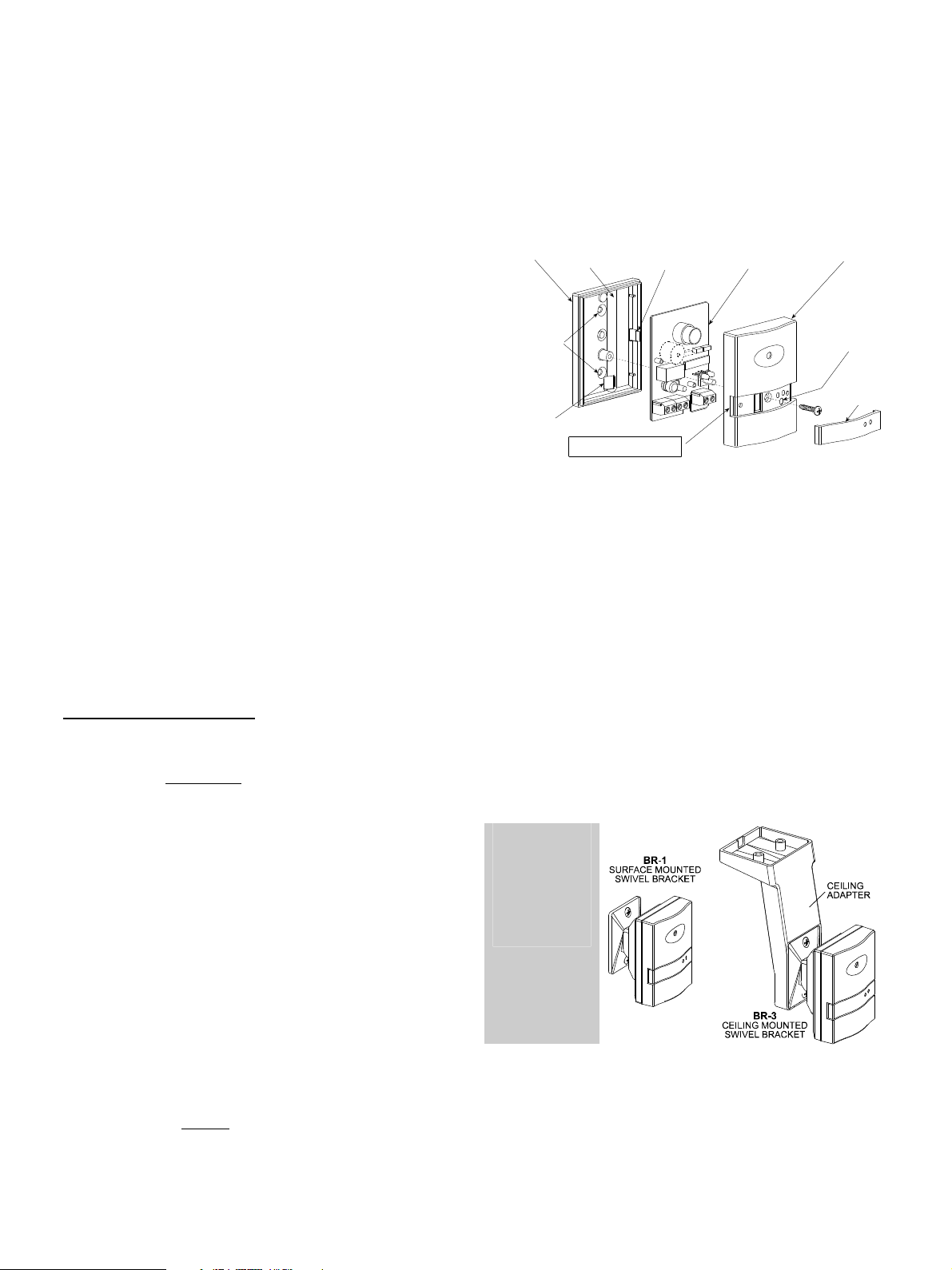
3.6. Optional Mounting Brackets (Fig. 3)
Two optional mounting brackets are available:
BR-1 Surface Mounted: Swivel, surface-mounted bracket for
greater flexibility when facing the protected window. The BR-1 is
adjustable 30° downward and 45° left, 45° right.
BR-3 – Ceiling Mounted: Swivel bracket kit for easy installation
on ceilings. Consists of the BR-1 and a ceiling mounting adapter.
Note: corner
installation is not
recommended
Figure 3. Optional Swivel Mounting Brackets
3.2 Disassembling the Detector (Fig. 2)
To disassemble the detector proceed as follows:
A. Pry loose one side of the trim strip, with a fingernail or a small
screwdriver. If the trim strip doesn't come loose easily, try the
other side. Remove the trim strip and save it for later use.
B. Remove the screw that fastens the front cover to the base and
take the cover off.
2 DE1896- GlassTech Installation Instructions
Page 3

3.7 Setting the Jumper Links (Fig. 4)
constantly when a malfunction (trouble) occurs and for 3 seconds
only upon alarm.
3.8 Wiring
To route wires into the detector, use the rectangular opening at
the bottom of the base, and the channel on the back of the base.
The channel allows wire routing from the ceiling along the back of
the detector and into the base. Proceed as follows (see Figure 5):
A. Connect the TAMP. N.C. terminals to a normally closed 24-
hour zone of the alarm control panel. The tamper contacts
open when the cover is removed.
B. Connect the N.C. relay terminals to a normally closed burglar
protection zone or perimeter zone of the control panel. The
relay contacts will open for 3 seconds upon alarm, or
permanently during power loss.
C. Connect the 12V (+) and (–) terminals to a 9 to 16 VDC
source. Reverse polarity protection is provided. If you intend
Figure 4. Printed Circuit Board Layout
A. The LED Latch Selector
Set the jumper to ON if you wish the red indicator LED to remain
illuminated after an alarm (memory indication). The memory
indication may be reset by temporarily removing the LED latch
jumper from its ON position or temporarily disconnecting the
supply voltage (a 1-second power down period is sufficient).
Setting the jumper to OFF disables the alarm memory. With the
memory disabled, the red indicator will light for about 3 seconds
upon alarm and will then extinguish.
B. The Glass Type Selector
The GlassTech is optimized for reliable glass break detection,
whatever the type of the glass pane – plate, laminated, wired
and tempered. Nevertheless, certain additional criteria have
extra benefits for the protection of plate and tempered glass.
These can included in the decision making process for a more
accurate, positive discrimination between true and false alarms.
For this reason, if the protected glass is of the plate or tempered
type, set the jumper to the P/T position (factory preset). If you
aren't sure of the type of glass, consult the glass supplier. If you
fail to identify the type of glass, or once you identify the glass as
laminated or wired, set the jumper to ALL.
C. Buzzer Selector (GlassTech-AM)
The anti-masking function (see Section 4.3) requires that the
buzzer be enabled. The buzzer selector may be set to OFF to
disable the buzzer if for some reason you wish to cancel this
function. If the jumper is set to ON, the buzzer will sound
4. TESTING
4. TESTING
4. TESTING4. TESTING
4.1. Initial Testing
A. During initialization, the detector samples the ambient noise.
Therefore, at power up, eliminate any strong irregular noise
such as loud radio, air-conditioner hum, loud knocking etc.
B. Power up the detector. The two LEDs will flash rapidly and, if
all is normal, they will both turn off within 60 seconds. With -
AM models, the front cover must be remounted before
this time expires: a trouble condition will result from
belated remounting of the cover.
If a malfunction or abnormal audio environment exists after
the first 60 seconds, both LEDs will light steadily until the
trouble is cleared. Simultaneously, the TRB output will pull to
ground and will remain grounded until the trouble is cleared.
As long as steady lighting is maintained, the detector is not
ready for operation. In the -AM model, the buzzer will sound
an alert, if the BUZZER jumper is set to ON.
Note: In addition, a diagnostic self-test routine is run at regular
intervals during normal operation (see Section 4.3).
C. Test the detector's stability by thumping the protected glass or
a flexible partition (if available in the room). The green LED
should respond by lighting briefly, but should go off
immediately and remain extinguished. The red alarm LED
shouldn't light during this test.
If the green LED continues to light or flickers sporadically
with apparently no background noise, try to change the
mounting location.
DE1896- GlassTech Installation Instructions 3
to use the alarm memory, make sure there is a provision for
temporary disconnection of power. The power supply requires
battery backup of 4 hours minimum (for UL-listed installations)
or in accordance with local regulations.
Figure 5. GLASSTECH Terminal Block Wiring
D. Connect the TRB to a 24-hour trouble zone, parallel to an
E.O.L. resistor, to cause a trouble alert in case of detector
trouble. For UL installations, the trouble output must be
connected to the trouble circuit of a UL-listed burglary
control unit.
Note: the detector and the control panel must have a common
ground (–) connection.
D. Set the glass type jumper to the P/T position and test the
detector's immunity to false alarms by creating 'household'
sounds: let a telephone ring, or clap your hands, or play a
loud audio recording or even break a dish or a drinking glass.
The green LED will flicker in response to any of these sounds,
indicating that the detector is functional. However, no alarm
should result - the red alarm LED must remain off.
Note: If the detector responds by alarming, replace it with
another unit and retest.
4.2 Glass Break Simulation Test
If tested in its regular operating mode, the detector won't respond
reliably to commercial glass break simulators. The GLASSTECH
generally identifies the sound generated by these simulators as a
false alarm. A special TEST switch has therefore been included,
to permit temporary downgrading of the GLASSTECH's signal
processing and decision making algorithms. This allows the unit
to be tested with simulators such as model FG-700 or FG-701.
Even in the test mode, a special combination of audio frequencies
must be generated for triggering the detector without actually
breaking glass. To achieve the correct effect, thump the protected
glass pane with a cushioned object, hard enough to trigger the
simulator. The displacement of the glass by the impact provides the
low frequency signal, and the simulator responds by sounding the
required high frequency signal.
Note: The FG-701 manual instructs you to switch certain glass
break detectors into the test mode by sounding a special signal.
Page 4

This is not applicable to the GlassTech which has a test switch.
W.E.E.E. Product Recycling Declaration
To assure success of the simulator-aided test, use a glass pane
of at least 0.5 x 0.5 m (1.5 x 1.5 ft). It is recommended (but not
obligatory) to set the glass type jumper to the ALL position.
A. Remove the trim strip from the detector's front cover, to
access the test switch (located just below the two LEDs).
B. Insert a pointed object (such as a pen) into the test switch
access hole and press for one second. This will switch the
GlassTech to the test mode for a 5-minute period. The Green
LED will light steadily throughout the test period.
C. Switch the simulator to the TEST and FLEX modes.
D. Hold the simulator close to the protected glass and press the
simulator's start button.
E. Within 8 seconds from pressing the start button, thump the
glass with a cushioned object hard enough to produce a low
frequency wave - take care not to shatter the glass.
F. The simulator should respond by sounding its own high-
frequency signal, and the detector should alarm. The alarm
can be verified by watching the red LED illuminate. In the -AM
model, the buzzer should sound, provided that it is enabled
with the buzzer jumper.
G. Remount the trim strip at the front. Normal operation resumes
automatically 5 minutes after having pressed the test switch.
Note: if the LED latch jumper is set to ON, the LED will light
constantly upon termination of the test. To extinguish the LED,
temporarily remove the latch jumper from the ON position or
momentarily disconnect the power supply to the detector.
WARRANTY
Visonic Limited (the “Manufacturer") warrants this product only (the "Product") to the original purchaser only (the
“Purchaser”) against defective workmanship and materials under normal use of the Product for a period of twelve
(12) months from the date of shipment by the Manufacturer.
This Warranty is absolutely conditional upon the Product having been properly installed, maintained and operated
under c onditions of normal use in accordance with the Manufacturers r ecommended installation and operation
instructions. Products which have bec ome defective for any other reason, according to the Manufacturers
discretion, such as improper installation, failure to follow recommended installation and operational instructions,
neglect, willful damage, misuse or vandalism, accidental damage, alteration or tampering, or repair by anyone
other than the manufacturer, are not covered by this Warranty.
The Manufacturer does not represent that this Product may not be com promised and/or circumvented or that the
Product will prevent any death and/or personal injury and/or damage to property resulting from burglary, robbery,
fire or otherwise, or that the Product will in all cases provide adequate warning or protection. The Product,
properly installed and m aintained, only reduces the risk of such events without warning and it is not a guarantee
or insurance that such events will not occur.
THIS WARRANTY IS EXCLUSIVE AND EXPRESSLY IN LIEU OF ALL OTHER WARRANTIES, OBLIGATIONS
OR LIABILITIES, WHETHER WRITTEN, ORAL, EXPRESS OR IM PLIED, INCL UDING ANY WARRANTY O F
MERCHANTABILITY OR FITNESS FOR A PARTICULAR PURPOSE, OR OTHERWISE. IN NO CASE SHALL
THE MANUFACTURER BE LIABLE TO ANYONE FOR ANY CO NSEQUENTIAL OR INCIDENTAL DAMAGES
FOR BREACH OF THIS WARRANTY OR ANY OTHER WARRANTIES WHATSOEVER, AS AFORESAID.
THE MANUFACTURER SHALL IN NO EVENT BE LIABLE FOR ANY SPECIAL, INDIRECT, INCIDENTAL,
CONSEQUENTIAL OR PUNITIVE DAMAGES OR FOR LOSS, DAMAGE, OR EXPENSE, INCLUDING LOSS
OF USE, PROFITS, REVENUE, OR GOODWILL, D IRECTLY OR INDIRECTLY ARISING FROM
PURCHASER’S USE OR INABILITY TO USE THE PRODUCT, OR FOR LO SS OR DESTRUCTION OF
OTHER PROPERTY OR FROM ANY OT HER CAUSE, EVEN IF MANUFACTURER HAS BEEN ADVISED OF
THE POSSIBILITY OF SUCH DAMAGE.
THE MANUFACTURER SHALL HAVE NO LIABILITY FOR ANY DEATH, PERSONAL AND/OR BODILY
INJURY AND/OR DAMAGE TO PROPERTY OR OTHER LOSS WHETHER DIRECT, INDIRECT, INCIDENTAL,
CONSEQUENTIAL OR OTHERWISE, BASED ON A CLAIM THAT THE PRODUCT FAILED TO FUNCTION.
For information regarding the recycling of this product you must contact the company from which you orignially purchased it. If you are discarding this product and not
returning it for repair then you must ensure that it is returned as identified by your supplier. This product is not to be thrown away with everyday waste.
Directive 2002/96/EC Waste Electrical and Electronic Equipment.
Important! conduct a simulation test at least once every 6
months.
4.3 Self-Diagnostic Routines
A. Regular Self Tests
All GlassTech models run a self-diagnostic routine once every 30
minutes, and if a malfunction is discovered, a TROUBLE period
begins - both LEDs light steadily, the trouble output pulls to
ground and the buzzer (in -AM models) sounds an alert. The
trouble indications will stop upon removal of the cause for trouble.
Note: The alarm relay is not affected by the trouble condition.
B. Anti-Masking (GlassTech -AM)
The anti-masking function protects against attempts at reducing
or totally suppressing the GlassTech's detection ability.
GlassTech models with the -AM suffix are equipped with an onboard buzzer and a buzzer ON/OFF jumper. For anti-masking
purposes, the buzzer emits a short quiet chirp once every 30
minutes. Any lasting deviation from the normal signal pickup level
will initiate a 1 minute period of extensive testing. If the audio
disturbance still exists after the extensive testing period, a trouble
indication, similar to the one obtained in regular self tests, will
result (see Para. A above). The buzzer sounds an alert for as
long as the masking condition exists.
Important! The anti masking capability can be checked only
when the power-up 1-minute test period is over. The detector will
start to indicate trouble within about 15 minutes after having been
masked. Removal of the masking will cause the trouble indication
to cease within a few seconds.
However, if the Manufacturer is held liable, whether directly or indirectly, for any loss or damage arising under this
limited warranty, THE MANUFACTURER'S MAXIMUM LIABILITY (IF ANY) SHALL NOT IN ANY CASE
EXCEED THE PURCHASE PRICE OF THE PRODUCT, which shall be fixed as liquidated damages and not as a
penalty, and shall be the complete and exclusive remedy against the Manufacturer.
When accepting the delivery of the Product, the Purchaser agrees to the said conditions of sale and warranty and
he recognizes having been informed of.
Some jurisdictions do not allow the exclusion or limitation of incidental or consequential damages, so these
limitations may not apply under certain circumstances.
The Manufacturer shall be under no liability whatsoever arising out of the corruption and/or malfunctioning of any
telecommunication or electronic equipment or any programs.
The Manufacturers obligations under this Warranty are limited s olely to repair and/or replace at the
Manufacturer’s discretion any Product or part thereof that may prove defective. Any repair and/or replacement
shall not extend the original W arranty period. The Manufacturer shall not be responsible for dismantling and/or
reinstallation costs. T o exercise this Warranty the Product m ust be returned to the Manufacturer freight pre-paid
and insured. All freight and insurance costs are the responsibility of the Purchaser and are not included in this
Warranty.
This warranty shall not be modified, varied or extended, and the Manufacturer does not authorize any person to
act on its behalf in the modification, variation or extension of this warranty. This warranty shall apply to the
Product only. All products, accessories or attachments of others used in conjunction with the Product, including
batteries, shall be covered solely by their own warranty, if any. The Manufacturer shall not be liable for any
damage or loss whatsoever, whether directly, indirectly, incidentally, consequentially or otherwise, caused by the
malfunction of the Product due to products, accessories, or attachments of others, including batteries, used in
conjunction with the Products. This Warranty is exclusive to the original Purchaser and is not assignable.
This Warranty is in addition to and does not affect your legal rights. Any provision in this warranty which is
contrary to the Law in the state or country were the Product is supplied shall not apply.
Warning:The user must follow the Manufacturer’s installation and operational instructions including testing the
Product and its whole system at least once a week and to take all necessary precautions for his/her safety and
the protection of his/her property.
1/08
EMAIL: info@visonic.com
INTERNET: www.visonic.com
VISONIC LTD. 2013 GLASSTECH DE1896- (REV. 10, 8/13)
4 DE1896- GlassTech Installation Instructions
R
 Loading...