

Page 1
*)':
Ultra Low-Current Wireless Audio Discriminator
,1752'8&7,21
The GFD-40W is a battery powered, ultra low current wireless
audio discriminator, sensitive to sounds above the cutoff
frequency of approximately 5 kHz. It is primarily designed to
detect the breakage of any type of glass. When activated by a
sound in the proper frequency range, the GFD-40W triggers a
plug-in, low power UHF transmitter module that sends a coded
alarm signal to t he control panel.
The detection sensitivity can be adjusted with an on-board
RANGE control, so that an alarm would be triggered only in
response to sounds of sufficient ampl itude. A jumper link on the
PC board is used for t emporary ac tivation of a DETECTOR LED,
which serves as a sound level monitor (see para. 3.5).
The transmitted RF signal consists of a SYSTEM code and a
CHANNEL code that perform t he following functions:
• The SYSTEM code serves as a password – the remote
receiver ignores RF signals other than the correctly coded
ones. A code match between the GFD-40W and the remote
receiver is obtained by selecting identical settings on an
8-position CODE swi tch in both units. It is possible to select
256 different system codes (see par a. 3.3).
• The CHANNEL code
determines which one of the
remote receiver's outputs
will be activated by the
transmitted RF signal. This
code is selected by
presetting the GFD-40W
4-position "CHANNEL"
selector (see para. 3.4).
Both detector and transmitter
are powered by an internal 9
Volt alkaline or lithium battery
housed within the unit 's case.
63(&,),&$7,216
ACOUSTIC
Detection Range: Up to 35 ft (10 m)*.
Cutoff Frequency: 5 kHz nominal
Microphone: Electret condenser.
* Varies with room shape, acoustics, temperature and humidity.
ELECTRICAL
Battery: 9-volt alkaline or lithium type.
Current Drain: 0.008 mA i n standby.
Battery Life: Up to 2 years in standby; c alculation is based on
initial full battery capacity of 0.5 Ah and operating conditions
within the limi ts of battery s pecifications.
Note: Although the battery should last 1 - 2 years, it is a good
practice to replace it ever y 12 months.
Visual Indicators:
ALARM LED - lights upon alarm.
DET. LED - indicates detection of ambient noise.
Testing: Built-in LED for ambient noise monitoring.
WIRELESS
Frequency (MHz): 315, 304, 404, 418, 433.92 or other
frequencies per local requirements.
Transmission Duration: 2 seconds
System Code: 8-bit digital word, 256 combinations, pulse width
modulation.
Channels: 4 channels, switch-sel ectable.
ENVIRONMENTAL
Operating Temperatur es: 0°C to 50°C (32°F to 122°F).
Storage Temperatures: –20°C to 60°C (-4°F to 140°F).
PHYSICAL
Dimensions (H x W x D): 110x63x25mm (4-5/16 x 2-1/ 2 x 1 in. ).
Weight: 67 gr ( approx. 2-1/2 oz).
Color: White.
Installation Instructions
,167$//$7,21
6HOHFWLQJ0RXQWL QJ/RFDWLRQ
The GFD-40W should be posi tioned close to and facing toward
the expected forced entry points (door, windows etc.). It is
inadvisable to mount t he unit on the wall through whic h intrusi on
could occur.
There should be a clear acous tic path between the unit and the
protected area. Do not mount the unit behind walls or around
corners from t he area to be c overed, as t he signal i t rec eives wi ll
be reduced. Any coverings or decorations (drapes, blinds etc.)
should be in place and taken into consideration during
adjustment.
,QVWDOODWLRQ
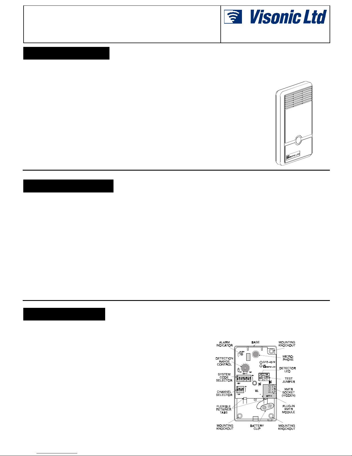
The detector unit is suitable for surface mounting, using the
mounting knockouts provided in the base ( see Figure 1).
A. Unpack the GFD-40W and save the nylon bag with the round
plastic cap for later use (see para. 3.7).
B. Remove the screw which secures the front cover to the case.
DE4031 1
C. Punch out two diagonally opposed mounti ng knockouts (see
Figure 1 for knockout locations ).
Figure 1. Inside View
Page 2

D. Secure the unit to the wall with 2 screws (use wall inserts if
required).
E. Connect a 9-volt alkaline or lithium battery to the battery clip.
6\VWHP&RGH6HOHFWLRQ
The code selector consists of an 8-key DIP switch, marked 1
through 8. Each key is set to eit her ON or OFF posi tion to cr eate
a unique digital system code combination (256 poss ibilities - see
Figure 2).
Figure 2. System Code Selector
Select the desired digital code so that it will match the one
selected on the companion receiver. All wireless detectors and
the receiver used in the alarm s ystem must be set to the same
digital code.
CAUTION: the code combination 2, 4, 5, 6, 7 ON / 1, 3, 8 OFF
is a factory test code that must not be used. Also avoid
often-used codes such as all keys ON, all keys OFF or
alternating ON-OFF s ettings.
All sounds affec ting the det ector c an be moni tored and displayed
by the test LED marked DETECTOR, provided that the
NORM/TEST jumper is placed in the TEST position (see Fig.
1).Check individual sounds, such as telephones and door chimes,
to find out whether they cause the detec tor LED to light. If they
do, gradually rotat e the range control counter clockwise until the
LED no longer lights.
Next, test the GFD-40W r esponse to sounds that should t rigger
an alarm. A good simulation for frequencies above 5 kHz is to
strike keys against the protected glass. You can also use a
commercially available, dedicated glass break simulator. If the
simulation does not trigger an alarm, gradually increase the range
control to a point where the test signal consistently causes the
unit to go into alarm.
In some cases, optimum sensitivity and maximum immunity to
false alarms c an be obtained by re-locating the GFD-40W.
Upon alarm, the ALARM indicator should light for 2 sec onds, and
a 2-second alarm tr ansmission shoul d take place. Veri fy that the
transmitted signal affects the correct zone in the control panel.
Important: Do not forget to return the NORM/TEST jumper to
NORM. Otherwise, the unit will draw excess current which will
result in shorter battery life.
&KDQQHO&RGH6HOHFWL RQ
The Visonic Ltd. wir eless security s ystems have a multi- channel
capability. Each GFD-40W audio discriminator can be set to
transmit any combination of 4 different channel codes. Each
channel code activates a particular output circuit of the
companion receiver. This feature is very useful for zoning
purposes - act ivation of differ ent zones at the contr ol panel.
Figure 3. Channel Code Select or
The channel selector consists of a 4-key DIP switch marked 1
through 4. The channel code transmitted by the detector is
selected by setting the corresponding switch(es) to the ON
position.
$GMXVWPHQWDQG7HVW
Allow one minute after power up for the unit to stabilize. Us e the
RANGE control to select the sensitivity best suited to each
application. The sensitivity should be set only as high as
necessary, to avoi d false alarms.
:$55$17<
:$55$17<
Visonic Ltd. and/or its subsidiaries and its affiliates ("the Manufacturer") warrants its
products hereinafter referred to as "the Product" or "Products" to be in conformance with
its own plans and specifications and to be free of defects in materials and workmanship
under normal use and service for a period of twelve months from the date of shipment by
the Manufacturer. The Manufacturer's obligations shall be limited within the warranty
period, at its option, to repair or replace the product or any part thereof. The Manufacturer
shall not be responsible for dismantling and/or reinstallation charges. To exercise the
warranty the product must be returned to the Manufacturer freight prepaid and insured.
This warranty does not apply in the following cases: improper installation, misuse,
failure to follow installation and operating instructions, alteration, abuse, accident or
tampering, and repair by anyone other than the Manufacturer.
This warranty is exclusive and expressly in lieu of all other warranties, obligations or
liabilities, whether written, oral, express or implied, including any warranty of
merchantability or fitness for a particular purpose, or otherwise. In no case shall the
Manufacturer be liable to anyone for any consequential or incidental damages for breach
of this warranty or any other warranties whatsoever, as aforesaid.
This warranty shall not be modified, varied or extended, and the Manufacturer does not
authorize any person to act on its behalf in the modification, variation or extension of this
warranty. This warranty shall apply to the Product only. All products, accessories or
attachments of others used in conjunction with the Product, including batteries, shall be
covered solely by their own warranty, if any. The Manufacturer shall not be liable for any
damage or loss whatsoever, whether directly, indirectly, incidentally, consequentially or
otherwise, caused by the malfunction of the Product due to products, accessories, or
attachments of others, including batteries, used in conjunction with the Products.
0DLQWHQDQFH
The proper adjustment and oper ation of the GFD-40W shoul d be
checked at leas t once a year, in acc ordance with para. 3.5.
To assure proper continuous functioning, the user should be
instructed t o perform a simulation as explained in para. 3.5, t o
assure an alarm output prior to each time the alarm system is
armed.
5HSODFLQJWKH&RYHU
Reposition the fr ont c over wi th
the grille at the top (over the
microphone). Secure with the
screw and insert the plastic
cap over the scr ew head (see
Figure 4).
Figure 4. Screw and Cap
The Manufacturer does not represent that its Product may not be compromised and/or
circumvented, or that the Product will prevent any death, personal and/or bodily injury
and/or damage to property resulting from burglary, robbery, fire or otherwise, or that the
Product will in all cases provide adequate warning or protection. User understands that a
properly installed and maintained alarm may only reduce the risk of events such as
burglary, robbery, and fire without warning, but it is not insurance or a guarantee that such
will not occur or that there will be no death, personal damage and/or damage to property
as a result.
The Manufacturer shall have no liability for any death, personal and/or bodily injury
and/or damage to property or other loss whether direct, indirect, incidental,
consequential or otherwise, based on a claim that the Product failed to function.
However, if the Manufacturer is held liable, whether directly or indirectly, for any loss or
damage arising under this limited warranty or otherwise, regardless of cause or origin, the
Manufacturer's maximum liability shall not in any case exceed the purchase price of the
Product, which shall be fixed as liquidated damages and not as a penalty, and shall be the
complete and exclusive remedy against the Manufacturer.
Warning: The user should follow the installation and operation instructions and among
other things test the Product and the whole system at least once a week. For various
reasons, including, but not limited to, changes in environmental conditions, electric or
electronic disruptions and tampering, the Product may not perform as expected. The user
is advised to take all necessary precautions for his /her safety and the protection of
his/her property.
6/91
VISONIC LTD (ISRAEL): P.O.B 22020 TEL-AVIV 61220 ISRAEL. PHONE: (972-3) 645-6789, FAX: (972-3) 645-6788
VISONIC INC. (U.S.A.): 10 NORTHWOOD DRIVE, BLOOMFIELD CT. 06002-1911. PHONE: (860) 243-0833, (800) 223-0020 U.S. FAX: (860) 242-8094
VISONIC LTD. (UK): UNIT 1, STRATTON PARK, DUNTON LANE BIGGLESWADE, BEDS. SG18 8QS. PHONE: (01767) 600857 FAX: (01767) 601098
VISONIC LTD. 1998 GFD-40W D-4031-0 NEW: DE4031- (REV. 2, 4/98 )
2 DE4031
 Loading...