

Page 1
*)'*)'$'
Audio Discriminators
,1752'8&7,21
The GFD-30 and GFD-30AD are flush-mounted, glass break audio
discriminators, sensitive to noises above a cutoff frequency of
approximately 5 kHz.
The GFD-30AD is fitted with an additi onal potentiometer to adjust the
lower cutoff frequency.
63(&,),&$7,216
Acoustical Detection Range: Up to 15 m (50 ft) radius (adjustable).
Varies with room shape, acoustics, temperature and humidity.
Coverage Area: Up to 500 sq m (5000 sq ft)
Cutoff Frequency: GFD-30, 5 kHz (nominal).
GFD-30AD, adjustable from 2-10 kHz.
Microphone: Electret Condenser.
Electrical Voltage: 9-16 VDC (prot e cted against reverse polarit y)
Current: 20 mA
Relay Output: Normally Closed (failsafe).18 ohm resistor in series
with contacts. Rating - 0.1A resistive/ 30 VDC.
,167$//$7,21
&RQVWUXFWLRQ
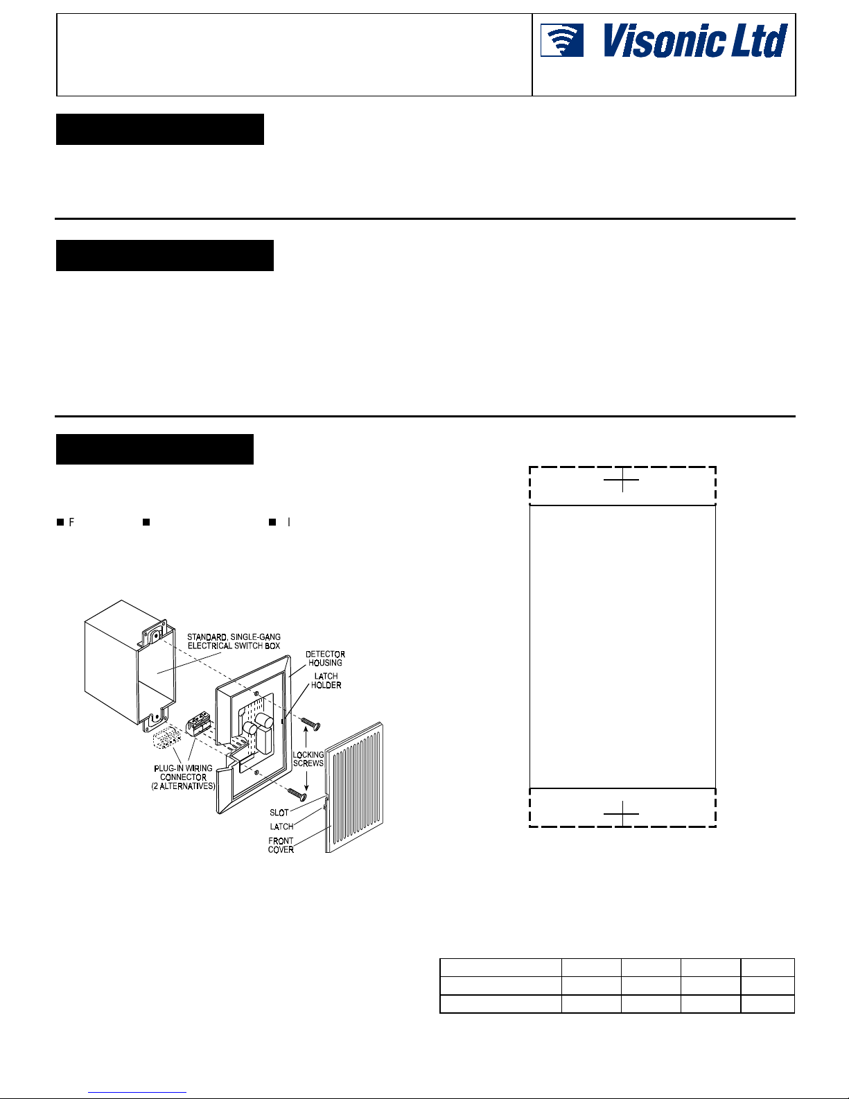
Figure 1 shows the GFD-30 component parts and method of as sem bl y.
The unit includes the following main parts:
Front Cover Detector Housin g Plug-in Wiring Connector.
A single-gang, electrical switch box is als o shown in Figure 1. This box
should be installed according to its specific instructions.
A. Opening the Detector
Release the front cover by inserting a small screwdriver into a front
cover slot and releasing it. See Figure 1.
Installation Instructions
Both units are designed to f it into virtually any standard, s ingle-gang,
electrical switch box - see Figure 1.
They can also be installed direc tly into a prepared space in the wall,
without a box enclosure.
Alarm Period: 2-3 seconds
Indicators: "ALM" LE D lights on alarm. "DET" LED light s to indicate
effect of ambient noises on discriminator.
Testing: Built-in tester with ambient noise monitori ng " DET" LED.
Operating Temperature: 14°F to 122°F (-10°C to 50°C).
Storage Temperature: -4°F to 140°F (-20°C to 60°C).
Physical Dimensions: 125 x 85 x 39 mm (5 x 3.3 x 1.5 in.)
Weight: 180 g (6.3 oz).
Color: White.
Actual size
GFD-30
Figure 1. GFD-30 Constr uction and Assembly
B. Closing the Detector
Position the front cover in t he detector housing with the small lat ches
aligned with their corresponding latch holders. Push the front cover
gently until a click is heard.
drawing which may be used when cutting the hole in the wall.
Figure 2 provides an actual size cutout
6HOHFWLQJWKH 0RXQWLQJ/RFDWLRQ
The detector should be positioned on walls or ceilings, close to and
facing toward the area to be covered (door, windows, etc.) There
be a clear audible path between the unit and the point s of entry. Do not
mount the detector behind walls or around corners from the area to be
covered as the signal it receives will be reduced. Also, any coverings or
decorations (drapes, blinds, etc.) should be in place and taken into
consideration during adjustment.
DE1893 1
should
Figure 2. Wall Cutout Drawing
:LULQJ
A. Wiring Size
Use #22 AWG or larger wires. The maximum wiring length between the
unit and its power source depends on the num ber of units c onnect ed i n
parallel and the wire gauge. The following table provides t he maximum
wiring length for a single unit, using different gauge wires.
Wiring Gauge 22 20 18 16
Wiring length (ft)
Wiring length (m)
If two or more units are connected in parallel, the maximum wiring
length described in the table should be divided by the number of units.
750 1100 1800 3000
230 330 550 900
Page 2
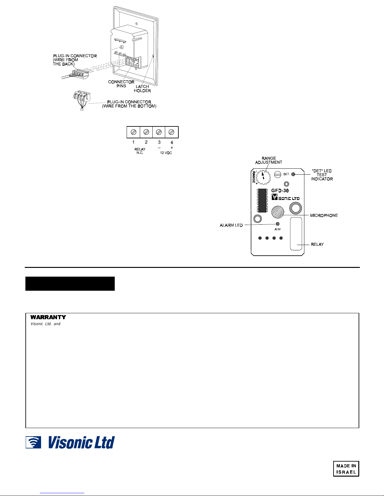
Figure 3. Mounting the Wiring Connector
B. Connector Position
For maximum wiring convenience the
plug-in connector can be installed onto t he
connector pins in 2 ways, according t o the
wiring entry and routing in the installation
box - see Figure 3.
Choose the most convenient mounting
position and wire the connector in the
following order (see Figure 4).
Figure 4.
Plug-In
Connector Wiri ng
C. Relay
Connect Relay N.C. terminals (pins 1 & 2) t o a normally clos ed burglar
protection zone of the control panel. Relay c ontacts will open when an
intruder is detected or during power loss.
The relay contacts are rated at 100 mA, 30 V DC maximum (resistive
load only). An 18-ohm resistor is internally c onnected in seri es with the
relay contacts.
D. Supply Voltage
Connect the 12 VDC (–) and (+) terminals (pins 3 & 4) to a 9 to 16
Volts
DC power source and check for correct polarity.
The power source should have a back-up battery that is capable of
supplying power for at least four hours of operation, during power
failure. Current drain of each sensor is approximately 20 mA.
E. Plugging In the Connector
Plug the connector onto the connector pins in the unit. Make sure that:
(1) The connector is mounted in the correct position - i.e., the
+12 VDC wire is plugged into pin 4.
(2) The connector is installed to the end of its pins.
$GMXVWLQJWKH &RYHUDJH$UHD
All sounds affecting t he detector are monitored and displayed by the
LED marked "DET". The effect of individual sounds, such as
telephones and door chimes, can be checked and adjust ments made
for optimum sensitivity and maximum immunity from false alarms.
The potentiometer mark ed "RANGE" is used to select the sensitivity
best suited to each application.
A good simulation for frequencies above 5 kHz is to rattle some keys or
to knock with ke ys on glass.
An alarm condition occurs when the LED marked "ALM" lights. The
GFD-30 should be set only as high as necessary, to avoid false alarms.
$GMXVWLQJ /RZHU )UHTXHQF\ &XWRII
/HYHO0RGHO*)'$'
The potentiometer mark ed "SENS" enables the lower cutoff frequency
to be adjusted approximately from 2 kHz to 10 kHz. Turning the
potentiometer counterclockwise lowers the cutoff frequency.
This adjustment allows you to further adjus t the lower cutoff frequenc y
and to effectively neutralize background noises at a spec if ic i nst allat ion,
achieving optimum sensitivity with minimum false alarms.
Figure 5. Printed Circuit Board
0$,17(1$1&(
The proper operation and adjustment of the GFD-30 discriminator
should be checked at least once a year accordi ng to Para. 3.4 and
3.5. To assure proper continuous functioning, the user should
:$55$17<
:$55$17<
Visonic Ltd. and/or its subsidiaries and its affiliates ("the Manufacturer") warrants its
products hereinafter referred to as "the Product" or "Products" to be in conformance with
its own plans and specifications and to be free of defects in materials and workmanship
under normal use and service for a period of twelve months from the date of shipment by
the Manufacturer. The Manufacturer's obligations shall be limited within the warranty
period, at its option, to repair or replace the product or any part thereof. The Manufacturer
shall not be responsible for dismantling and/or reinstallation charges. To exercise the
warranty the product must be returned to the Manufacturer freight prepaid and insured.
This warranty does not apply in the following cases: improper installation, misuse,
failure to follow installation and operating instructions, alteration, abuse, accident or
tampering, and repair by anyone other than the Manufacturer.
This warranty is exclusive and expressly in lieu of all other warranties, obligations or
liabilities, whether written, oral, express or implied, including any warranty of
merchantability or fitness for a particular purpose, or otherwise. In no case shall the
Manufacturer be liable to anyone for any consequential or incidental damages for breach
of this warranty or any other warranties whatsoever, as aforesaid.
This warranty shall not be modified, varied or extended, and the Manufacturer does not
authorize any person to act on its behalf in the modification, variation or extension of this
warranty. This warranty shall apply to the Product only. All products, accessories or
attachments of others used in conjunction with the Product, including batteries, shall be
covered solely by their own warranty, if any. The Manufacturer shall not be liable for any
damage or loss whatsoever, whether directly, indirectly, incidentally, consequentially or
otherwise, caused by the malfunction of the Product due to products, accessories, or
attachments of others, including batteries, used in conjunction with the Products.
VISONIC LTD (ISRAEL): P.O.B 22020 TEL-AVIV 61220 ISRAEL. PHONE: (972-3) 645-6789, FAX: (972-3) 645-6788
VISONIC INC. (U.S.A.): 10 NORTHWOOD DRIVE, BLOOMFIELD CT. 06002-1911. PHONE: (860) 243-0833, (800) 223-0020 FAX: (860) 242-8094
VISONIC LTD. (UK): UNIT 1, STRATTON PARK, DUNTON LANE BIGGLESWADE, BEDS. SG18 8QS. PHONE: (01767) 600857 FAX: (01767) 601098
Internet Web Site: www.visonic.com
VISONIC LTD. 1998 GFD-30 D-1893-0 NEW: DE1893- (REV. 2, 8/98)
be instructed to perform simulation as explained in Para. 3.4, to
assure an alarm output prior t o each time the alarm system is armed.
The Manufacturer does not represent that its Product may not be compromised and/or
circumvented, or that the Product will prevent any death, personal and/or bodily injury
and/or damage to property resulting from burglary, robbery, fire or otherwise, or that the
Product will in all cases provide adequate warning or protection. User understands that a
properly installed and maintained alarm may only reduce the risk of events such as
burglary, robbery, and fire without warning, but it is not insurance or a guarantee that such
will not occur or that there will be no death, personal damage and/or damage to property
as a result.
The Manufacturer shall have no liability for any death, personal and/or bodily injury
and/or damage to property or other loss whether direct, indirect, incidental,
consequential or otherwise, based on a claim that the Product failed to function.
However, if the Manufacturer is held liable, whether directly or indirectly, for any loss or
damage arising under this limited warranty or otherwise, regardless of cause or origin, the
Manufacturer's maximum liability shall not in any case exceed the purchase price of the
Product, which shall be fixed as liquidated damages and not as a penalty, and shall be the
complete and exclusive remedy against the Manufacturer.
Warning: The user should follow the installation and operation instructions and among
other things test the Product and the whole system at least once a week. For various
reasons, including, but not limited to, changes in environmental conditions, electric or
electronic disruptions and tampering, the Product may not perform as expected. The user
is advised to take all necessary precautions for his/her safety and the protection of his/her
property.
6/91
2 DE1893
 Loading...