

Page 1
DISCOVERY QUAD
MCW
Wireless PowerCode Quad PIR Detector
1. FEATURES
• Employs a real quad element low-noise pyroelectric sensor
• Includes a fully supervised PowerCode transmitter
• Patented sophisticated motion analysis algorithm - True Motion
Recognition (TMR™)
• Two-position vertical adjustment for coverage pattern
• Integral swivel bracket for wall or ceiling installation
• Programmable motion event counter - ON or OFF (default)
• Front and back tamper switches for improved tamper protection
• Full stabilization achieved 30 seconds after power up
• After detection, the detector disables itself to save battery
power. It reverts to the ready state if there is no subsequent
detection throughout the following 2-minute period
2. SPECIFICATIONS
OPTICAL
Detector Type: Quad element low-noise pyroelectric sensor.
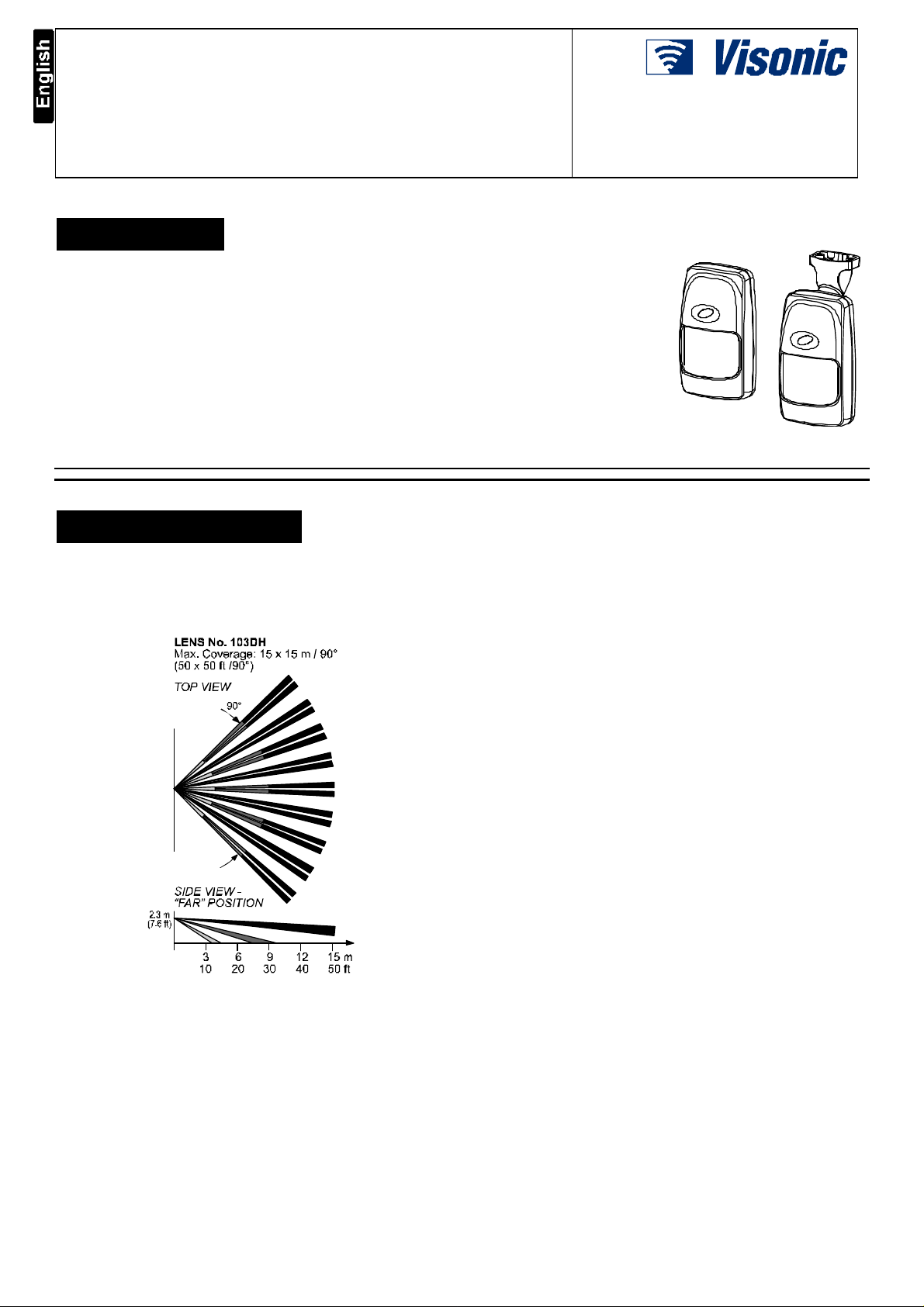
Detection Pattern: 90° wide angle lens with 19 quad zones in 3
detection layers. Max. coverage is 15 x 15 m (50 x 50 ft).
Adjustment: 2-position vertical adjustment scale: FAR and NEAR.
Figure 2. Coverage Pattern
ELECTRICAL
Internal Battery: 3 V Lithium battery, Panasonic CR-2 or
equivalent
Nominal Battery Capacity: 750 mAh
Standby Current Drain: 0.015 mA
Transmit Current Drain: 20 mA (including LED)
Battery Life Expectancy: 3 years (for typical use)
Battery Supervision: Automatic reporting of battery status with
each alarm and with periodic supervision message.
FUNCTIONAL
True Motion Event Verification: 2 position selector - 1 (OFF) or
2 (ON) motion events.
Alarm Period: 3 seconds.
Installation Instructions
• Automatic termination of
walk-test after 15 minutes
• Low current consumption
• Microprocessor-controlled
temperature compensation
• Sealed chamber protects the
optical system
• White light protection
• Elegantly styled, sturdy case
• Keyhole-shaped slot for
easy removal of PCB
Visual Indications:
LED lights for about 3 seconds upon transmission of alarm &
tamper messages and upon each motion detection in the walk
test mode.
LED flashes during the power-up stabilization period, or after
restoring (pressing) the tamper switch.
LED does not light upon transmission of supervision
messages.
Rearm Timer: Rearms the detector 2 minutes after the last alarm.
Timer disabled in the walk test mode.
WIRELESS
Frequency (MHz): 315, 433.92, 868.95, 869.2625 or other
frequencies according to local requirements.
Transmission Sequence: 3 data bursts at variable intervals
within 3 seconds.
Encoding: 24-bit ID, over 16 million possible combinations.
Total Message Length: 36 bits.
Tamper Alert: Reported when a tamper event occurs and in any
subsequent message, until the tamper switch is restored.
Supervision Message: Once per 15 minutes, 60 minutes or
according to local standards.
MOUNTING
Height:
With bracket : Up to 3.6 m (12 ft)
Without bracket: 2 - 2.6 m (6.5 - 8.5 ft)
Installation Options:
With bracket: Surface or ceiling
Without bracket: Surface or corner
Bracket Adjustment: 20° downward, 20° left and right.
ENVIRONMENTAL
RFI Protection: >30 V/m up to 1000 MHz.
Operating Temperatures: -10°C to 50°C (14°F to 122°F).
Storage Temperatures: -20°C to 60°C (-4°F to 140°F).
Compliance with Standards: Designed to meet FCC Part 15
and Directive 1999/5/EC of the European Parliament.
PHYSICAL
Dimensions (H x W x D): 117 x 65 x 47 mm.
(4-5/8 x 2-9/16 x 1-7/8 in.).
Weight: 92 g (3.25 oz) without bracket, 107 g (3.75 oz) with
bracket.
Color: White
PATENTS: U.S. Patent No. 5,693,943
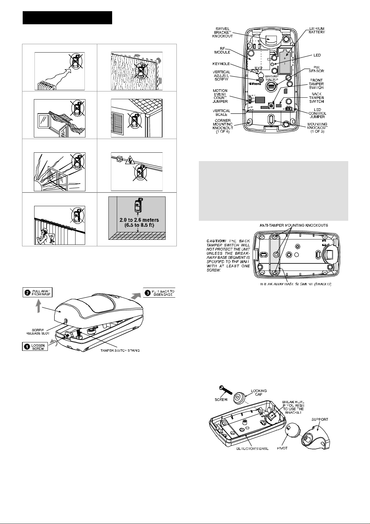
Figure 1. External View
Page 2
3. INSTALLATION
3.1 Installation Hints
To minimize false alarms:
Do not aim at heat sources Mount on solid, stable surfaces
Do not expose to air draughts
Do not install outdoors
Prevent direct sunlight from
reaching the detector
Do not install behind
partitions
Keep wiring away from electrical
power cables
3.2 Battery Insertion
It is recommended to power up the detector and let the target
receiver “learn” the transmitter’s ID before actual installation. This
can be done only after battery installation.
1st.Remove the front cover as shown in Figure 3.
Figure 3. Cover Removal
B. Insert the battery into the battery clip - observe polarity (see
Figure 4).
3rd. Press the tamper switch once and release it. This will perform
the reset necessary for smooth power up.
4th. Put the cover on and observe the LED. It will flash until the
detector stabilizes (within about 30 seconds).
Figure 4. Inside View
3rd.Punch out the mounting knockouts at the base (for surface
mounting) or mounting knockouts at the angled sides of the
base (for corner mounting).
Attention! The unit has a special tamper switch under the PCB. As
long as the PCB is seated firmly within the base, the switch lever will
be pressed against a special break-away base segment that is
loosely connected to the base (Figure 5). Be sure to fasten the
break-away segment to the wall. If the detector unit is forcibly
removed from the wall, this segment will break away from the base,
causing the tamper switch to open. It is advisable to pierce the
anti-tamper knockouts from within the base outward, while
pressing the rear surface of the break-away segment against a
piece of wood.
Figure 5. Anti-Tamper Break-Away Base Segment
4th.Hold the base against the wall at the selected location, mark
the drilling points, drill the holes and attach the base to the
wall.
5th.Return the PCB to its place: align the ”keyhole” with the head
of the vertical adjustment screw, press the PCB against the
base, slide the PCB up and temporarily tighten the screw.
3.5 Mounting with Swivel Bracket
1st.Remove the front cover as shown in Figure 3.
2nd.Loosen the vertical adjustment screw, slide the PCB down
and remove it via the “keyhole” (see Figure 4).
3rd.Punch out the large knockout in the round bulge at the top
part of the base (see Figure 6).
4th.Assemble the bracket as shown in Figure 6.
3.3 Enrolling the Transmitter ID
Refer to the target receiver’s installation instructions and follow
the procedure given there for “teaching” the transmitter's ID. It is
much easier to carry out this operation in close proximity to the
receiver.
3.4 Mounting without Swivel Bracket
1st.Remove the front cover as shown in Figure 3.
2nd.Loosen the vertical adjustment screw, slide the PCB down
and remove it via the “keyhole” (see Figure 4).
5th.Rotate the bracket to the desired position (see Figure 7) but
do not yet tighten the screw fully.
Figure 6. Attaching the Bracket
Page 3

Figure 7. Wall and Ceiling Positions of Bracket
6th.Mark the points for drilling through the two mounting holes of
the bracket. Attach the bracket to the mounting surface.
G. Tilt down or swivel the detector to face the desired direction.
Figure 8 shows the tilt/swivel possibilities.
regardless of the jumper position and then enters walk-test mode.
After 15 minutes the detector enters normal mode in which the
LED functions according to the LED control jumper position.
3.8 Vertical Adjustment
Refer to Figure 10. Loosen the vertical adjustment screw and slide
the printed circuit board up or down to obtain the desired
coverage. When done, tighten the screw well.
Figure 8. Tilt/Swivel Limits
3.6 Setting the Motion Event Counter
The location of the motion event jumper is shown in Figure 4.
Refer to Figure 9 below and mount the jumper as desired.
Figure 9. Motion Event Counter Setting Options
3.7 Setting the LED Control Jumper
ON Position: Setting the jumper as shown enables
the LED. Remember that the detector disables
itself for 2-minutes after detection!
OFF Position: Setting the jumper as shown
disables the LED.
Note: At power up or reset, the LED flashes for 30 seconds
Figure 10. Vertical Adjustment
3.9 Walk Testing
Upon battery insertion or closing of the cover (which results in
closing of the tamper switch) the detector goes into walk-test
mode and automatically exits the mode after 15 minutes.
1st. Set the motion event counter as required (see Paragraph
3.6).
2nd. Adjust the vertical angle as desired (see Paragraph 3.8).
3rd. Remount the cover and fasten the case closure screw. This
results in the resetting of the detector and the start of walktest mode.
4th. Wait until the LED stops flashing (about 30 seconds).
5th. Walk-test the entire protected area by walking slowly across
the detector's field of view, observing the LED. Pause for 5
seconds after each detection to allow the detector to complete
its 3-transmission sequence (see Appendix A); the LED will
light for about 3 seconds.
6th. When the walk-test is completed (after 15 minutes), the
detector's setting automatically changes according to the LED
control jumper setting.
Notes:
1. The OFF setting is recommended to prevent unauthorized
people from tracing the detector’s coverage pattern.
2. If the LED is disabled, you may use the control panel’s
visual and audible indicators to verify proper function of the
detector.
Attention! To assure proper function of the detector, the
range and coverage area should be checked at least twice a
year. Furthermore, the user should be instructed to perform
a walk test at the far end of the coverage pattern to assure
an alarm signal prior to each time the alarm system is armed.
4. MISCELLANEOUS
COMMENTS
4.1 Product Limitations
Visonic Ltd. wireless systems are very reliable and are tested to
high standards. However, due to their low transmitting power and
limited range (required by FCC and other regulatory authorities),
there are some limitations to be considered:
A. Receivers may be blocked by radio signals on or near their
operating frequencies, regardless of the code selected.
B. A receiver can only respond to one transmitted signal at a
time.
C. Wireless equipment should be tested regularly to determine
whether there are sources of interference and to protect
against faults.
4.2 Frequency Allocations for
Wireless Devices in European (EU)
Countries
• 433.92 MHz has no restriction in any EU member state.
• 315 MHz is not allowed in any EU member state.
Page 4

• 868.95 MHz (wide band) is allowed in all EU member states.
• 869.2625 MHz (narrow band) is not restricted in any EU
member state.
4.3 Compliance with Standards
This device complies with the essential requirements and provisions of
Directive 1999/5/EC of the European Parliament and of the Council of 9
March 1999 on radio and telecommunications terminal equipment.
The 315 MHz model of this device complies with Part 15 of the
FCC Rules. Operation is subject to the following two conditions:
(1) This device may not cause harmful interference, and (2) this
device must accept any interference that may be received,
including interference that may cause undesired operation.
The user is cautioned that changes or modifications to the
unit, not expressly approved by the party responsible,
could void the user's FCC authority to operate the
equipment.
APPENDIX A. THE VISONIC LTD. POWERCODE
SYSTEM
A-1. The PowerCode Message
Format
The PowerCode message transmitted by the DISCOVERY
QUAD MCW includes the 24-bit ID and a status report (see Fig.
A1).
messages transmitted automatically at 1 hour or 15 minute
intervals. This marker will be OFF in all other messages.
• Transmitter Type: A special marker indicates the type of
the transmitter:
n Supervised or non-supervised
n Reports or does not report restorals after alarm
The DISCOVERY QUAD MCW does not report restorals after
alarms.
• Checksum: Checksum bits at the end of the message allow
the receiver to determine whether an incoming message is
valid (error-free). This feature considerably enhances the
reliability of the wireless communication link.
Figure A1. Transmitted Data
A message includes the following data:
• Detector's ID: Any message transmitted starts with the 24-
bit ID assigned to the particular detector unit.
• Tamper / Restore: Upon removal of the unit's front cover, a
message will be transmitted with a "tamper marker" ON. If
the unit's cover is put back, a message will be transmitted
with the tamper marker OFF ("Tamper Restore").
• Alarm: Once the detector is in alarm, a message will be
transmitted with an "alarm marker" ON.
• Low Battery: A special battery condition marker is used to
report the battery status in any message. The battery is
tested once an hour and if found low, the "low battery
marker" is set to ON in all following messages.
• Supervision Message: A special "supervision message
marker", when set to ON, identifies the periodic supervision
WARRANTY
Visonic Ltd. and/or its subsidiaries and its affiliates ("the Manufacturer") warrants its
products hereinafter referred to as "the Product" or "Products" to be in conformance
with its own plans and specifications and to be free of defects in materials and
workmanship under normal use and service for a period of twelve months from the
date of shipment by the Manufacturer. The Manufacturer's obligations shall be
limited within the warranty period, at its option, to repair or replace the product or
any part thereof. The Manufacturer shall not be responsible for dismantling and/or
reinstallation charges. To exercise the warranty the product must be returned to the
Manufacturer freight prepaid and insured.
This warranty does not apply in the following cases: improper installation, misuse,
failure to follow installation and operating instructions, alteration, abuse, accident or
tampering, and repair by anyone other than the Manufacturer.
This warranty is exclusive and expressly in lieu of all other warranties, obligations or
liabilities, whether written, oral, express or implied, including any warranty of
merchantability or fitness for a particular purpose, or otherwise. In no case shall the
Manufacturer be liable to anyone for any consequential or incidental damages for
breach of this warranty or any other warranties whatsoever, as aforesaid.
This warranty shall not be modified, varied or extended, and the Manufacturer does
not authorize any person to act on its behalf in the modification, variation or
extension of this warranty. This warranty shall apply to the Product only. All
products, accessories or attachments of others used in conjunction with the Product,
including batteries, shall be covered solely by their own warranty, if any. The
Manufacturer shall not be liable for any damage or loss whatsoever, whether directly,
indirectly, incidentally, consequentially or otherwise, caused by the malfunction of
the Product due to products, accessories, or attachments of others, including
batteries, used in conjunction with the Products.
A-2. Anti-Collision
To overcome message collisions at the receiving end,
PowerCode transmitters transmit 3 data bursts at random
intervals, with 6 repetitions of the same message in each burst
(Fig. A2). This redundancy improves the probability of
reception.
Note: Periodic supervision messages are an exception to this
rule - they consist of a single 6-message burst.
Figure A2. Anti-Collision Transmission Sequence
The Manufacturer does not represent that its Product may not be compromised and/or
circumvented, or that the Product will prevent any death, personal and/or bodily
injury and/or damage to property resulting from burglary, robbery, fire or otherwise, or
that the Product will in all cases provide adequate warning or protection. User
understands that a properly installed and maintained alarm may only reduce the risk
of events such as burglary, robbery, and fire without warning, but it is not insurance
or a guarantee that such will not occur or that there will be no death, personal
damage and/or damage to property as a result.
The Manufacturer shall have no liability for any death, personal and/or bodily
injury and/or damage to property or other loss whether direct, indirect, incidental,
consequential or otherwise, based on a claim that the Product failed to function.
However, if the Manufacturer is held liable, whether directly or indirectly, for any loss
or damage arising under this limited warranty or otherwise, regardless of cause or
origin, the Manufacturer's maximum liability shall not in any case exceed the
purchase price of the Product, which shall be fixed as liquidated damages and not
as a penalty, and shall be the complete and exclusive remedy against the
Manufacturer.
Warning: The user should follow the installation and operation instructions and
among other things test the Product and the whole system at least once a week. For
various reasons, including, but not limited to, changes in environmental conditions,
electric or electronic disruptions and tampering, the Product may not perform as
expected. The user is advised to take all necessary precautions for his/her safety
and the protection of his/her property.
6/91
VISONIC LTD. (ISRAEL): P.O.B 22020 TEL-AVIV 61220 ISRAEL. PHONE: (972-3) 645-6789, FAX: (972-3) 645-6788
VISONIC INC. (U.S.A.): 10 NORTHWOOD DRIVE, BLOOMFIELD CT. 06002-1911. PHONE: (860) 243-0833, (800) 223-0020 FAX: (860) 242-8094
VISONIC LTD. (UK): FRASER ROAD, PRIORY BUSINESS PARK, BEDFORD MK44 3WH. PHONE: (0870) 730-0800 FAX: (0870) 730-0801
INTERNET: www.visonic.com
VISONIC LTD. 2002 DISCOVERY QUAD MCW DE3633- (REV. 1, 6/02)
 Loading...