

Visonic DISCOVERY DUO, DISCOVERY DUO/AM Installation Instructions Manual
DE1835 DISCOVERY DUO / DISCOVERY DUO AM Installation Instructions 1
DISCOVERY DUO
DISCOVERY DUO/AM
Dual-Technology Microwave/PIR Intrusion Detectors
Installation Instructions
1. FEATURES
Cylindrical optics improves detection and false alarm immunity.
True Motion Recognition™ (TMR) algorithm (patented)
distin- guishes between the true motion of a human body and
other disturbances which invariably cause false alarms
DRO-stabilized MW microstrip technology (patented)
MW Motion Simulator simulates the effect of a human body
moving in the MW field (for MW self-test - patent pending)
Range control for adjusting the MW coverage
Integral swivel bracket for wall or ceiling installation
Sealed chamber protects the pyroelectric element from
insects.
PIR self-test by applying a short heat pulse (DISCOVERY
DUO/AM only)
Programmable motion event
counter (1 or 2 events)
Simple-to-use, two-position
vertical adjustment
TEST input to enable/disable
the walk test LED remotely
(per new European standard)
Open collector trouble output
Anti-masking protection
(DISCOVERY DUO/AM only)
White light protection.
Figure 1. General View
2. SPECIFICATIONS
Input Voltage: 9 to 16 VDC
Current Drain: About 28 mA @ 12 VDC
PIR SECTION
Detector: Low noise dual-element pyroelectric sensor
Tripping Indication: LED flashes green for up to 5 seconds
Motion Event Verification Counter: Selectable, 1 or 2 events
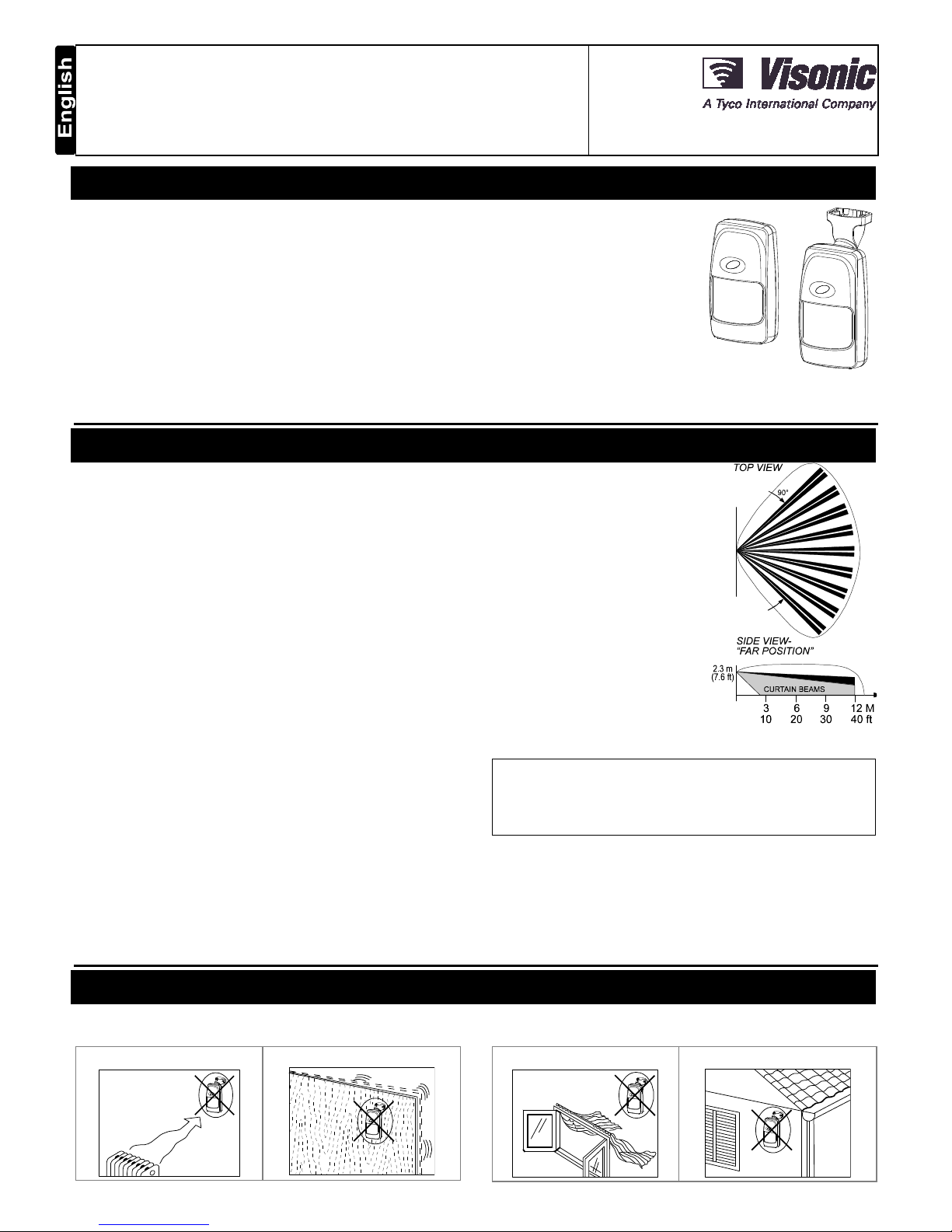
Lens Data (No. 105DH - see Figure 2)
No. of Beams: 36 in two layers (curtain beams in bottom layer)
Max. Coverage: 12 x 12 m (40 x 40 ft) / 90° field of view
Vertical Adjustment: FAR and NEAR, by sliding the circuit
board along a two-position scale.
MW SECTION
Oscillator: Microstrip DRO-stabilized Doppler module
Frequency: 10.525 GHz (U.S.A. only) or 2.45 GHz (Europe)
Detection Range: Adjustable from 25% to 100% (3 m to 12 m)
Tripping Indication: LED glows green for up to 5 seconds
ALARM, TAMPER & TROUBLE DATA
Alarm Indication: LED glows red for 1.3 to 5 seconds if both
detectors trip
Relay Contacts: N.C., rated at 0.1 A resistive / 30 VDC; 18
resistor in series with contacts
Alarm Duration: 1.3 to 5 seconds
Tamper Switch: N.C., rated at 50 mA resistive / 30 VDC
Trouble Output: Open collector, 100 mA max., with 18
resistor
in series and 47 k
pull-up (see Figure 11)
Masking Detection Delay (/AM version only): About 60 seconds
Trouble/ Masking Indication: LED alternately flashes green and
red and TRB output pulls LOW until the detector is reset.
MOUNTING
Height: Up to 3.6 m (12 ft)
Room Size: 8 - 12 m (24 -
40 ft) in the “FAR” position;
2
- 8 m (6 - 24 ft) in the NEAR
position.
Bracket Adjustment: 20°
downward, 20° left and right.
Installation Options: Surface or
corner (without bracket); surface
or ceiling (with bracket)
ENVIRONMENTAL
RFI Protection: >30 V/m up to
1000 MHz.
Operating Temperatures: -10°C
to 50°C (14°F to 122°F).
Storage Temperatures: -20°C to
60°C (-4°F to 140°F).
Figure 2. Coverage Pattern
Standards: Complies with Part 15 of the FCC Rules.
This device is designed to comply with the essential requirements
and provisions of Directive 1999/5/EC of the European Parliament
and of the Council of 9 March 1999 on radio and
telecommunications terminal equipment.
2.45 GHz has no restriction in any EU member state.
To comply with the Canadian standard RSS-210, this device
must be operated indoors only to provide maximum shielding
and to prevent interference to licensed services.
PHYSICAL
Size (H x W x D): 117 x 65 x 47 mm (4-5/8 x 2-9/16 x 1-7/8 in.).
Weight: 109 g (3.85 oz) w/o bracket, 124 g (4.4 oz) with bracket.
PATENTS
U.S. Patents 5,237,330 and 5,693,943 (other patents pending)
3. INSTALLATION
3.1 Installation Hints
To minimize false alarms:
Do not aim at heat sources
Mount on solid, stable surfaces
Do not expose to air drafts
Do not install outdoors
2 DE1835 DISCOVERY DUO / DISCOVERY DUO AM Installation Instructions
Prevent direct sunlight from
reaching the detector
Keep wiring away from
electrical power cables
Do not install behind partitions
In addition, a few important rules must be observed while selecting a
mounting location:
1. Microwave radiation passes through glass and non-metallic
walls. Be sure to adjust the MW range so that it does not
exceed the room limits, or else motion in the next room or
moving traffic along the outer side of the wall will cause the
MW detector to trip.
2. Large reflecting objects (especially metals) in the coverage
area can distort the microwave detector's coverage pattern.
3. If two DISCOVERY DUO units are installed in the same room
or on opposite sides of a shared wall, they should not face
each other and must be mounted at least 2 meters apart.
4. Do not install the DISCOVERY DUO in places where one of
the two detector circuits alarms constantly or intermittently,
due to environmental interference.
NOTE: DISCOVERY DUO-AM users are advised to mount the
unit in locations where inadvertent approach to less than 1 m
(3 ft) from the detector is unlikely to occur.
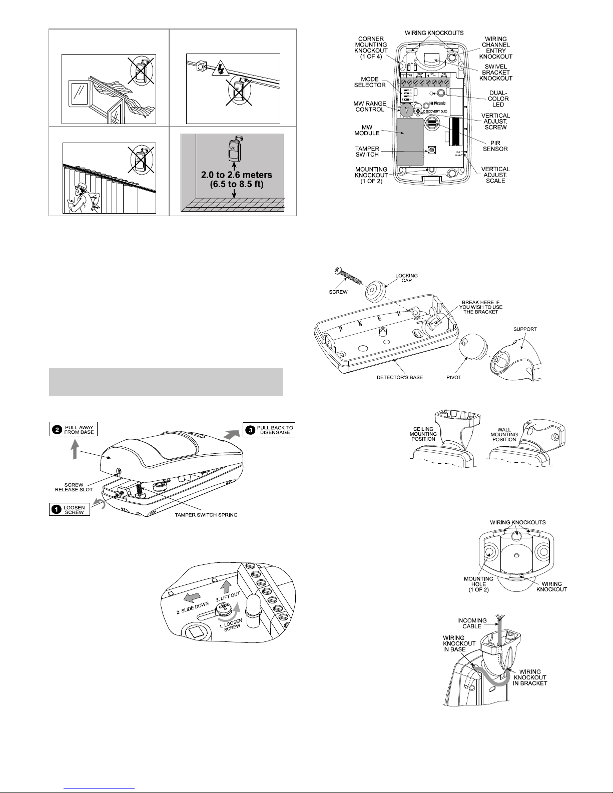
3.2 Mounting without Swivel Bracket
1. Remove the front cover as shown in Figure 3.
Figure 3. Cover Removal
2. Loosen the vertical adjustment screw, slide the PCB down and
remove it via the “keyhole” (see Figure 4).
3. Pull the PCB straight
out and put it aside
until required again.
4. Refer to Figure 5 and
punch out the
mounting knockouts
at the rear wall of
the base (for surface
mounting) or at the
angled sides (for
corner mounting).
Figure 4. PCB Removal
5. Punch out any one of the wiring knockouts shown in Figure 5.
6. Hold the base against the wall at the selected installation
location, mark the points for drilling and drill the holes (insert
the plastic dowels supplied if necessary).
7. Pass the wires through the wiring inlets into the base and
attach the base to the wall using the screws supplied.
8. Return the PCB to its place within the base.
9. Proceed to wire the terminal block as instructed in Para. 3.4.
Figure 5. Inside View
3.3 Mounting with Swivel Bracket
1. Remove the front cover as shown in Figure 3.
2. Remove the PCB (see Figure 4) and put it temporarily aside.
3. Punch out the large knockout in the round bulge at the top
part of the base (see Figure 6)
Figure 6. Attaching the Bracket
4. Assemble the
bracket as
shown in
Figure 6.
5. Rotate the
bracket to the
desired
position (refer
to Figure 7)
but do not yet
tighten the
screw fully.
Figure 7. Wall and Ceiling Positions
6. Punch out the selected wiring
knockouts in the bracket base
(see Fig. 8).
7. Press the bracket against the
mounting surface and mark
the points for drilling. Drill out
the holes and insert plastic
dowels, if necessary. Attach
to the wall with the 2 screws.
Figure 8. Bracket Rear
8. Route the cable through
the bracket and into the
detector as shown in
Figure 9.
9. Attach the bracket to the
mounting surface using
the two screws
supplied.
10. Tilt down or swivel the
detector to face the
desired direction. Fig.
10 shows the various
possibilities of tilting and
swiveling.
Figure 9. Routing the Cable
 Loading...