

Page 1
DE1260 DISCOVERY QUAD Installation Instructions 1
DISCOVERY QUAD
Advanced QUAD PIR Motion Detector
Installation Instructions
1. FEATURES
Quad element pyroelectric sensor
Patented sophisticated motion analysis algorithm - True
Motion Recognition™
Integral swivel bracket for wall or ceiling installation
Sealed chamber protects the optical system
Programmable motion event counter (1, 2 or 3 events)
Three-position vertical pattern adjustment
Low current consumption
Microprocessor-controlled temperature compensation
Test input to remotely enable/disable the walk-test LED (per
new European standard)
Free terminal for connecting an E.O.L. resistor
Snap-in pet alley mask
White light protection
Elegantly styled, sturdy case
Keyhole-shaped slot for easy removal of PCB
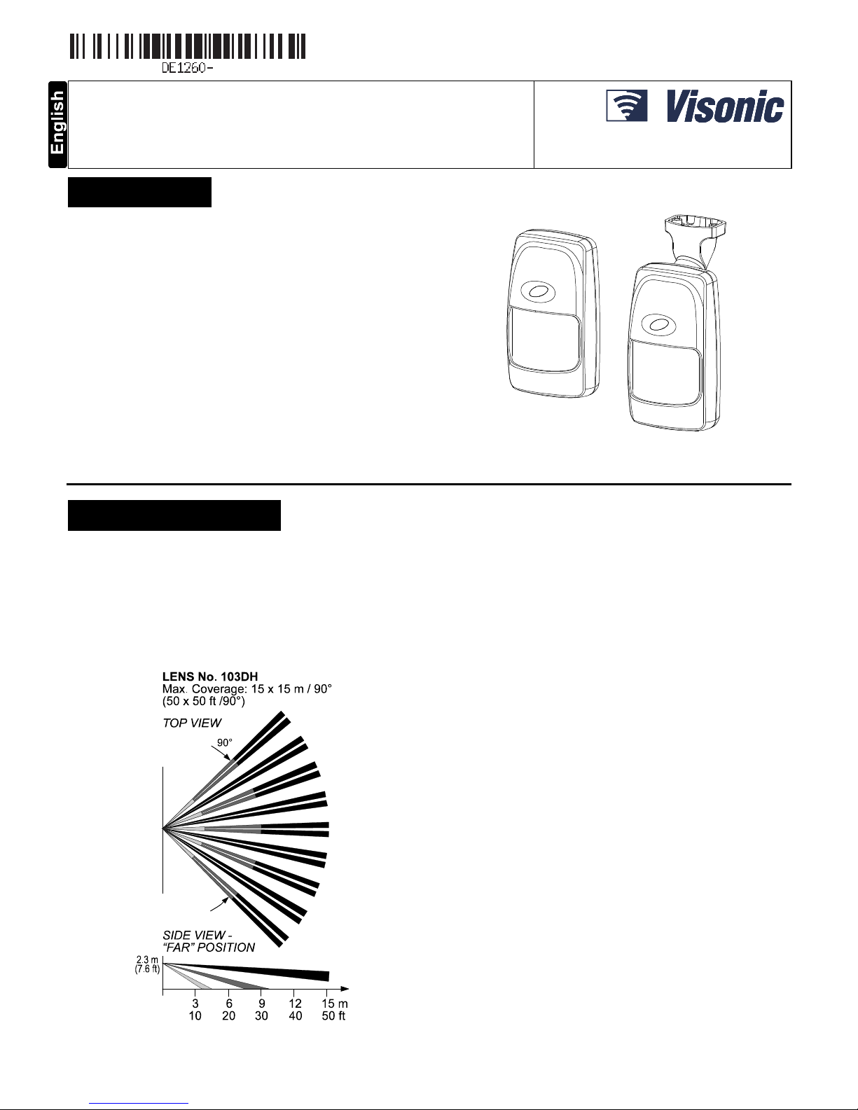
Figure 1. The Discovery Quad Detector
2. SPECIFICATIONS
OPTICAL
Detection Pattern: 90° wide angle lens with 19 quad zones in 3
detection
layers. Max. coverage is 15 x 15 m (50 x 50 ft).
Pet Alley: Plastic mask may be fitted internally, leaving only 9
quad zones in a single layer, with the same view angle and
coverage area as above.
Adjustment: 3-position vertical adjustment scale: PET, FAR,
NEAR.
Figure 2. Coverage Pattern
ELECTRICAL
Input Voltage: 9 to 16 VDC
Current @ 12 VDC: 10 mA standby, 19 mA on alarm (LED ON)
Alarm Relay: Normally closed (fail-safe) contacts with 18-ohm
resistor in series. Rating - 0.1 A resistive / 30 VDC.
Tamper Output: Normally closed contacts rated at 50 mA
resistive / 30 VDC.
Alarm Period: 4 seconds.
True Motion Event Verification: 3 position selector - 1, 2 or 3
motion events.
LED Control: Walk test enabled / disabled by internal link
Detector Type: Quad element low-noise pyroelectric sensor.
MOUNTING
Height: Up to 3.6 m (12 ft)
Room Size:
Up to 15 m (50 ft) in the “FAR” and “PET” positions
2 - 8 m (6 - 24 ft) in the NEAR position.
Installation Options:
Surface or corner (without bracket);
surface or ceiling (with bracket).
Bracket Adjustment: 20° downward, 20° left and right.
ENVIRONMENTAL
RFI Protection: >30 V/m up to 1000 MHz.
Operating Temperatures: -10°C to 50°C (14°F to 122°F).
Storage Temperatures: -20°C to 60°C (-4°F to 140°F).
PHYSICAL
Dimensions (H x W x D): 117 x 65 x 47 mm.
(4-5/8 x 2-9/16 x 1-7/8 in.).
Weight: 98 g (3.4 oz) without bracket, 113 g (4 oz) with bracket.
PATENTS
U.S. Patent No.: 5,693,943
Page 2
2 DE1260 DISCOVERY QUAD Installation Instructions
3. INSTALLATION
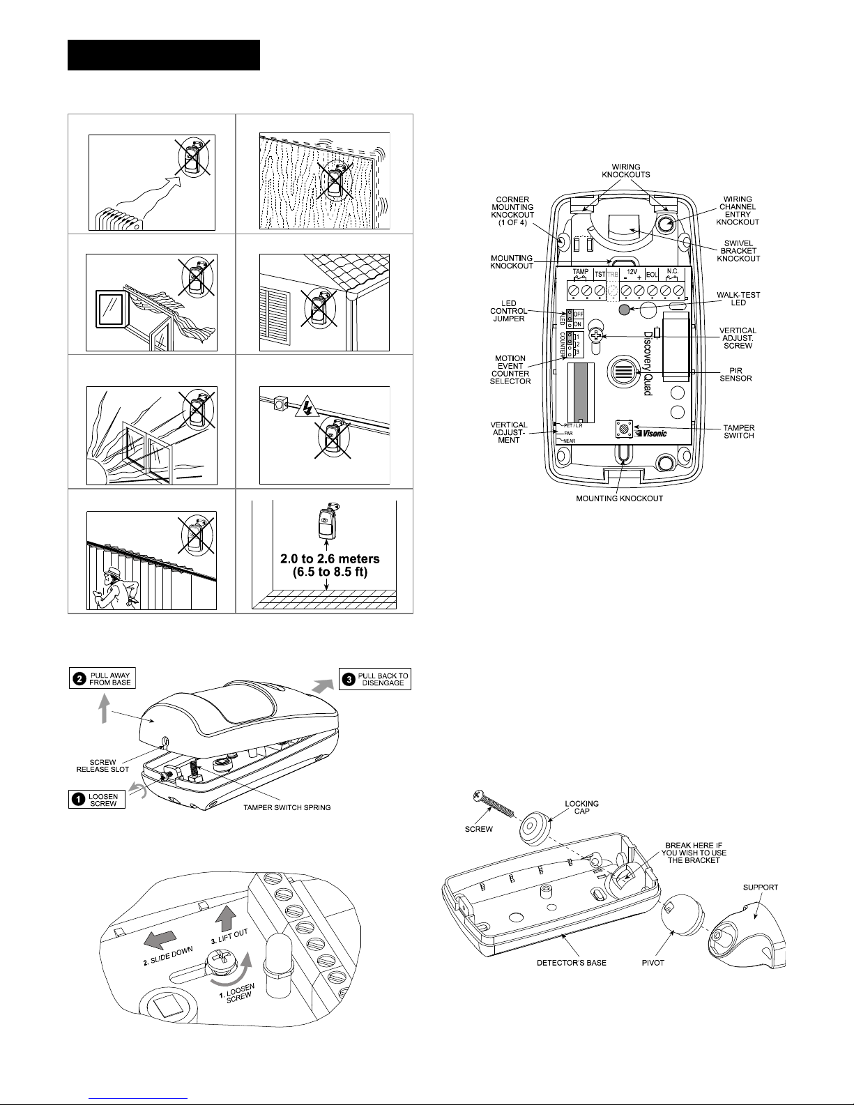
3.1 Installation Hints
To minimize false alarms:
Do not aim at heat sources
Mount on solid, stable surfaces
Do not expose to air draughts
Do not install outdoors
Prevent direct sunlight from
reaching the detector
Keep wiring away from
electrical power cables
Do not install behind partitions
3.2 Mounting without Swivel Bracket
A. Remove the front cover as shown in Figure 3.
Figure 3. Cover Removal
B. Loosen the vertical adjustment screw, slide the PCB down
and remove it via the “keyhole” (see Figure 4).
Figure 4. PCB Removal
C. Pull the PCB straight out and put it aside until required
again.
D. Refer to Figure 5 and punch out the mounting knockouts
at the rear wall of the base (for surface mounting) or
mounting knockouts at the angled sides of the base (for
corner mounting).
Figure 5. Inside View
E. Punch out any one of the wiring knockouts shown in Figure 5.
F. Hold the base against the wall at the selected installation
location and mark the points for drilling.
G. Drill the holes and insert the plastic anchors supplied (if
necessary).
H. Pass the wires through the wiring inlets into the base and
attach the base to the wall using the screws supplied.
I. Return the PCB to its place: align the ”keyhole” with the head
of the vertical adjustment screw, press the PCB against the
base, slide the PCB up and temporarily tighten the screw.
J. Proceed to wire the terminal block as instructed in Para. 3.5.
3.3 Mounting with Swivel Bracket
A. Remove the front cover as shown in Figure 3.
B. Remove the PCB (see Figure 4) and put it temporarily aside.
C. Punch out the large knockout in the round bulge at the top
part of the base (see Figure 6)
Figure 6. Attaching the Bracket
D. Assemble the bracket as shown in Figure 6.
E. Rotate the bracket to the desired position (see Figure 7) but
do not yet tighten the screw fully.
Page 3

DE1260 DISCOVERY QUAD Installation Instructions 3
Figure 7. Wall and Ceiling Positions of Bracket
F. Punch out the selected wiring knockouts in the bracket (see
Figure 8).
Figure 8. Bracket Base as Viewed from the Rear
G. Press the bracket against the mounting surface and mark the
points for drilling. Drill out the holes and insert plastic anchors.
H. Route the cable through the bracket and into the detector as
shown in Figure 9.
I. Attach the bracket to the mounting surface using the two
screws supplied.
Figure 9. Routing the Cable
J. Tilt down or swivel the detector to face the desired direction.
Figure 10 shows the tilt/swivel possibilities.
Figure 10. Tilt/Swivel Limits
3.4 Using the Pet Alley Mask
If the presence of pets is expected within the protected site,
proceed as follows:
A. Separate the lens retainer from the front cover, as shown in
Figure 11.
B. Push the prefabricated plastic mask into place within the lens
retainer, as shown in Figure 12.
C. Remount the lens retainer within the front cover.
Figure 11. Releasing the Lens Retainer
Figure 12. Inserting the Mask into Place
3.5 Wiring
The terminal block wiring shown in Figure 13 is self explanatory.
Note: The E.O.L. terminal is simply a connection point for an
E.O.L. resistor, if the circuit requires one.
Figure 13. Terminal Block Wiring
3.6 Setting the Motion Event Counter
The location of the motion event jumper is shown in Figure 5.
Refer to Figure 14 below and mount the jumper as desired.
Figure 14. Motion Event Counter Setting Options
Page 4

4 DE1260 DISCOVERY QUAD Installation Instructions
3.7 Vertical Adjustment
Refer to Figure 15. Slacken the vertical adjustment screw and
slide the printed circuit board up or down to obtain the desired
coverage. When done, tighten the screw well.
Figure 15. Vertical Adjustment
3.8 Setting the LED Control Jumper
ON Position Setting the jumper as shown will
enable the LED, allowing you to walk test the
detector.
OFF Position: Setting the jumper as shown will
disable the walk-test LED.
Note: At power up, the LED flashes for 50 seconds (regardless of
the jumper position) and then operates as determined by the
jumper position.
IMPORTANT! The TST terminal may be used while the LED
jumper is set to OFF for remote control of the walk-test
LED without removing the detector's front cover:
Grounding the TST terminal through an external switch will
enable the LED,
Applying +12 VDC to the TST terminal (as shown in Figure
13) or letting the terminal "float" will disable the LED.
After walk testing, it is recommended to disable the LED to
prevent unauthorized people from tracing the detector’s coverage
pattern.
3.9 Walk Testing
A. Set the motion event count jumper, the vertical angle
adjustment and the LED control jumper as instructed in
Paragraphs 3.6, 3.7 and 3.8, respectively.
B. Remount the cover back in its place and fasten the case
closure screw.
C. Walk across the detector’s field of view at various distances
from the detector, and verify proper detection throughout the
detector's coverage area (the red LED will illuminate for
several seconds each time your motion is detected).
Note: If the LED is disabled, you may use the control panel’s
visual and audible indicators to verify proper function of the
detector.
Attention! To assure proper function of the detector, the
range and coverage area should be checked at least twice a
year. Furthermore, the user should be instructed to perform a
walk test at the far end of the coverage pattern to assure an
alarm signal prior to each time the alarm system is armed.
The digital circuit of this device has been tested and found to
comply with the limits for a Class B digital device, pursuant to
Part 15 of the FCC Rules. These limits are designed to provide
reasonable protection against harmful interference in residential
installations. This equipment generates, uses and can radiate
radio frequency energy and, if not installed and used in
accordance with the instructions, may cause harmful interference
to radio and television reception. However, there is no guarantee
that interference will not occur in a particular installation. If this
device does cause such interference, which can be verified by
turning the device off and on, the user is encouraged to eliminate
the interference by one or more of the following measures:
– Re-orient or re-locate the receiving antenna.
– Increase the distance between the device and the receiver.
– Connect the device to an outlet on a circuit different from the
one which supplies power to the receiver.
– Consult the dealer or an experienced radio/TV technician.
WARRANTY
Visonic Limited (the “Manufacturer") warrants this product only (the "Product") to the or iginal purchaser only (the
“Purchaser”) against defective workmanship and materials under normal use of the Product for a period of twelve
(12) months from the date of shipment by the Manufacturer.
This Warranty is absolutely conditional upon the Product having been properly installed, maintained and operated
under conditions of normal use in accor dance with the Manufacturers recommended installation and operation
instructions. Products which have become defective for any other reason, according to the Manufacturers
discretion, such as improper installation, failure to follow recom mended installation and operational instructions,
neglect, willful damage, misuse or vandalism, acc idental damage, alteration or tampering, or repair by anyone
other than the manufacturer, are not covered by this Warranty.
The Manufacturer does not represent that this Product may not be compr omised and/or circumvented or that the
Product will prevent any death and/or personal injury and/or damage to property resulting from burglary, robbery,
fire or otherwise, or that the Product will in all cases provide adequate warning or protection. The Product,
properly installed and maintained, only reduces the risk of such events without warning and it is not a guarantee
or insurance that such events will not occur.
THIS WARRANTY IS EXCLUSIVE AND EXPRESSLY IN LIEU OF ALL OTHER WARRANTIES, OBLIGATIONS
OR LIABILITIES, WHETHER WRITTEN, ORAL, EXPRESS OR IMPLIED, INCLUDING ANY WARRANTY OF
MERCHANTABILITY OR FITNESS FOR A PARTICULAR PURPOSE, OR OTHERWISE. IN NO CASE SHALL
THE MANUFACTURER BE LIABLE TO ANYONE FOR ANY CONSEQUENTIAL OR INCIDENTAL DAMAGES
FOR BREACH OF THIS WARRANTY OR ANY OTHER WARRANTIES WHATSOEVER, AS AFORESAID.
THE MANUFACTURER SHALL IN NO EVENT BE LIABLE FOR ANY SPECIAL, INDIRECT, INCIDENTAL,
CONSEQUENTIAL OR PUNITIVE DAMAGES OR FOR LOSS, DAMAGE, OR EXPENSE, INCLUDING LOSS
OF USE, PROFITS, REVENUE, OR GOODWILL, DIRECTLY OR INDIRECTLY ARISING FROM
PURCHASER’S USE OR INABILITY TO USE THE PRODUCT, OR FOR LOSS OR DESTRUCTION OF
OTHER PROPERTY OR FROM ANY OTHER CAUSE, EVEN IF MANUFACTURER HAS BEEN ADVISED OF
THE POSSIBILITY OF SUCH DAMAGE.
THE MANUFACTURER SHALL HAVE NO LIABILITY FOR ANY DEATH, PERSONAL AND/OR BODILY
INJURY AND/OR DAMAGE TO PROPERTY OR OTHER LOSS WHETHER DIRECT, INDIRECT, INCIDENTAL,
CONSEQUENTIAL OR OTHERWISE, BASED ON A CLAIM THAT THE PRODUCT FAILED TO FUNCTION.
However, if the Manufacturer is held liable, whether directly or indirectly, for any loss or damage arising under this
limited warranty, THE MANUFACTURER'S MAXIMUM LIABILITY (IF ANY) SHALL NOT IN ANY CASE
EXCEED THE PURCHASE PRICE OF THE PRODUCT, which shall be fixed as liquidated damages and not as a
penalty, and shall be the complete and exclusive remedy against the Manufacturer.
When accepting the delivery of the Product, the Purchaser agrees to the said c onditions of sale and warranty and
he recognizes having been informed of.
Some jurisdictions do not allow the exclusion or limitation of incidental or c onsequential damages, so these
limitations may not apply under certain circumstances.
The Manufacturer shall be under no liability whatsoever arising out of the corruption and/or m alfunctioning of any
telecommunication or electronic equipment or any program s.
The Manufacturers obligations under this W arranty are limited solely to repair and/or replace at the
Manufacturer’s discretion any Product or part ther eof that may prove defective. Any repair and/or replacement
shall not extend the original Warranty period. The Manufacturer s hall not be responsible for dismantling and/or
reinstallation costs. To exercise this Warranty the Product must be returned to the Manufacture r freight pre-paid
and insured. All freight and insurance costs are the r esponsibility of the Purchaser and are not included in this
Warranty.
This warranty shall not be modified, varied or extended, and the Manufacturer does not authorize any person to
act on its behalf in the modification, variation or extension of this warranty. This warranty shall apply to the
Product only. All products, accessories or attachments of others used in conjunction with the Product, including
batteries, shall be covered solely by their own warranty, if any. The Manufacturer shall not be liable for any
damage or loss whatsoever, whether directly, indirectly, incidentally, consequentially or otherwise, caused by the
malfunction of the Product due to products, ac cessories, or attachments of others, including batteries, us ed in
conjunction with the Products. This Warranty is exclus ive to the original Purchaser and is not assignable.
This Warranty is in addition to and does not af fect your legal rights. Any provision in this warranty which is
contrary to the Law in the state or country were the Product is supplied shall not apply.
Warning: The user must follow the Manufacturer’s installation and operational instructions including testing the
Product and its whole system at least once a week and to take all necessary precautions for his/her s afety and
the protection of his/her property.
1/08
EMAIL: info@visonic.com
INTERNET: www.visonic.com
VISONIC LTD. 2014
DISCOVERY QUAD DE1260- (REV. 7, 7/14)
W.E.E.E. Product Recycling Declaration
For information regarding the recycling of this product you must contact the company
from which you orignially purchased it. If you are discarding this product and not
returning it for repair then you must ensure that it is returned as identified by your
supplier. This product is not to be thrown away with everyday waste.
Directive 2002/96/EC Waste Electrical and Electronic Equipment.
 Loading...