

Page 1

DE1011 1
CORAL PLUS
Temperature-Compensated PIR Detector
Installation Instructions
1. INTRODUCTION
The CORAL PLUS passive infrared detector is a new, advanced
version of the popular CORAL featuring an increased detection range,
improved stability and enhanced RFI protection (greater than 30 V/m).
The special advantage of the CORAL PLUS is its high-temperature
compensation for maximum "catch" performance, and its unique lowtemperature compensation for optimum false-alarm rejection.
The pyroelectric sensor of the CORAL PLUS is
enclosed in a sealed chamber, protected from insects
and air drafts. The pulse counter may be switched
between 1 and 3 pulses, as desired.
CORAL PLUS has a selection of four interchangeable
lenses - the appropriate lens for each application can
be selected to match the desired coverage.
2. SPECIFICATIONS
OPTICAL
Detection Patterns: 5 interchangeable lenses - see Figure 1.
Adjustment: Vertical, +2° to -12° calibrated scale.
ELECTRICAL
Voltage: 9 to 16 VDC.
Current: 17 mA at 12 VDC, 21 mA at 16 VDC
Alarm Output: Normally closed (fail-safe) contacts. 18 ohm resistor
in series with contacts. Rating - 0.1 A resistive / 30 VDC.
Tamper Output: Normally closed, rated 0.5 A resistive / 30 VDC.
Alarm Period: 2-3 seconds.
Pulse Counter: 2 position selector, 1 or 3 pulse operation.
LED: Walk test enabled or disabled with internal link.
Detector: Dual-element low noise pyroelectric sensor.
MOUNTING
Surface or corner (without brackets).
Mounting Height: Up to 3.6 m (12 ft).
Mounting Brackets: See Para. 3.3.
ENVIRONMENTAL
Operating Temperature: -10°C to 50°C (14°F to 122°F).
Storage Temperature: -20°C to 60°C (-4°F to 140°F).
RFI Protection: >30 V/m to 1000 MHz.
PHYSICAL
Size: 60 x 104 x 32 mm (2.4 x 4.1 x 1.3 in.).
Weight: 77 g (2-3/4 oz).
Color: White.
MODELS AVAILABLE
CORAL PLUS: Regular model
CORAL PLUS X: Model without tamper switch
PATENTS
U.S. Patent No. Des. 346,567
Lens A. Wide Angle (standard)
34 beams in 3 detection layers
Max. Range 15 x 15 m (50 x 50 ft)
Lens C. Ultra Wide Angle
34 beams in 3 detection layers
Max. Range 13.5 x 18 m (45 x 60 ft)
Lens D. Pet Alley
14 beams in a single layer
Max. Range 15 x 15 m (50 x 50 ft)
Lens 306. Cylindrical
7 curtain type beams
Max. Range 9 x 9 m (30 x 30 ft)
Lens B. Long Range
Narrow angle corridor pattern
Max. Range 3 x 27 m (10 x 90 ft)
Note: To allow extra free height for
pets, set the vertical adjustment scale
to +2°. Install the detector at a height
that places the detection pattern at
least 1 ft (30 cm) above the pet’s
activity.
Note: This lens is used for improved
detection in close proximity to the
detector. Motion occurring at least
1 m (3 ft) away from the detector will
be reliably detected .
Figure 1. Coverage Patterns
3. INSTALLATION
3.1 Mounting
The CORAL PLUS can be installed directly on a wall (surface
mounted) or in a corner. For optional swivel brackets, see Para. 3.3
and Figure 4. Always mount the unit on a firm and stable surface.
A. Select the mounting location so that the expected motion of an
intruder would cross the beams of the coverage pattern.
B. Select the most convenient mounting height. Built-in installation
aids enable you to mount the unit anywhere up to a 3.6 m (12 ft)
height. An accurate adjustment table (Table 1) determines the
recommended angles for various combinations of range and
mounting height.
C. CORAL PLUS is extremely immune to air turbulence and RF
interference (RFI). However, to minimize possible false alarms, it
is highly recommended to avoid aiming the detector at heaters,
sources of light or windows subjected to direct sunlight. Also avoid
running wiring close to high power electrical cables.
D. To open the front cover, remove the screw at the bottom of the
unit. Separate and remove the front cover from the base.
Page 2
2 DE1011
E. Mount the base (equipped with the printed circuit board) in the
location and height selected for optimum coverage. For surface
mounting use the two knockouts at the back of the base; for
corner mounting use the knockouts on the angled sides. The unit
must be fastened firmly to the mounting surface.
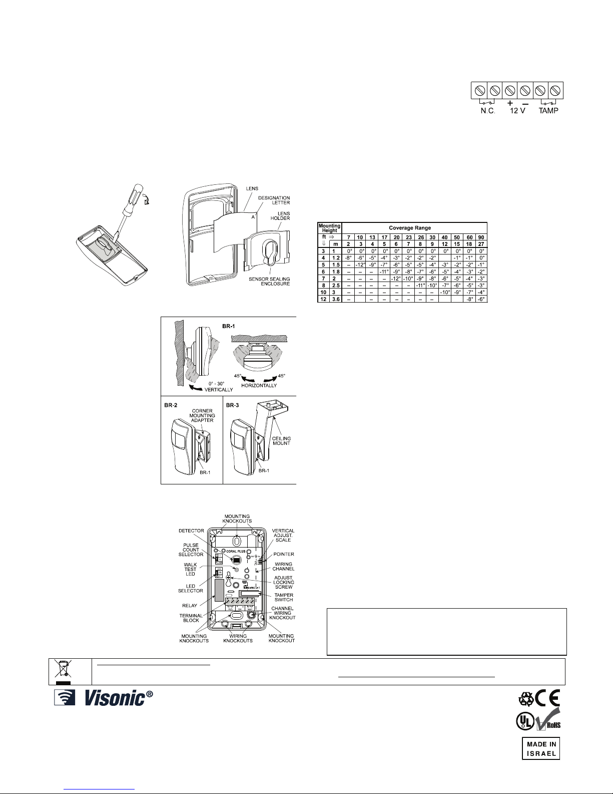
3.2 Changing Lenses
To change a lens, remove the screw at the bottom of the unit and
open the front cover. Insert a small screwdriver blade into the slot
between the lens holder and the cover. Lever the handle outward to
release the lens holder (Fig. 2).
Insert the new lens with the smooth surface outside and the lens
designation letter in the upper right corner (Fig. 3). Carefully center
the lens so that the distance from its edges to the edge of the cover is
the same on each side of the cover. Holding the lens firmly in place,
align the lens holder as shown in Figure 3 and push it toward the
cover until a click is heard.
Figure 2. Lens Holder Removal Figure 3. Lens Assembly
3.3 Optional Swivel Brackets
The BR-1 is a swivel,
surface-mounted bracket for
greater flexibility when
setting the detection range.
It is adjusable 30° downward and 45° left, 45° right
(Figure 4). The BR-2 is a
swivel bracket kit for room
corners. It consists of the
BR-1 and a corner adapter.
The BR-3 is a swivel
bracket kit for ceilings. It
consists of the BR-1 and a
ceiling adapter.
ATTENTION: With swivel
brackets in use, the
effective detection range
may differ from that
indicated in Table 1 - the
vertical adjusting scale.
Figure 4. Optional Swivel Brackets
3.4 Wiring
To route the wires into the
detector, use either the wiring
knockouts (see Figure 5) or the
wiring channel and its knockout
on the back. The channel allows
routing wires from the ceiling
under the base and then inside.
Connect wires to the terminal
block in the following order.
Refer to Figure 6.
A. Connect the TAMP. N.C.
terminals to a normally closed
24-hour protection zone of the
control panel. The tamper
contact will open when the
cover is removed.
Figure 5. Inside View
B. Connect the N.C. relay terminals to a normally closed burglar
protection zone of the control panel. Relay contacts will open
when motion is detected or during power loss.
For installations in Canada, the N.C. relay must be connected
to an end-of-line resistor supervised zone.
C. Connect the 12V (+) and (–) terminals
to a 9 - 16 Volt DC power source
(observe polarity). The power supply
must have at least 4 hours of battery
backup. The unit’s current drain is
approximately 17 mA.
Figure 6. Terminal Block
3.5 Vertical Adjustment
The vertical adjustment scale (printed on the upper right corner of the
p.c. board) and the plastic pointer on the base indicate in degrees the
vertical angle between the horizontal line of the unit and the upper
detection layer. Table 1 gives the recommended scale setting for
various combinations of mounting height and coverage distance.This
allows fast, easy pattern adjustment from +2° to -12° downward
according to the installation height and the required coverage range.
Table 1 - Vertical Adjusting Scale
Example: if you
require a range of
12 m (40 ft) and
wish to install the
sensor 1.8 m (6 ft)
above the ground,
set the vertical
adjustment Scale
to -5°.
All CORAL PLUS sensors are factory preset to -4°. To change the
vertical pattern adjustment, loosen the screw which fastens the printed
circuit board to the base. Slide the p.c. board up or down to the desired
angle and tighten the screw firmly. A keyhole shaped slot permits easy
removal of the PCB for maintenance by just loosening its securing screw.
Note: In pet alley installations (lens D), set the scale to +2°, and
Install the unit at a height that enables directing the detection pattern
about 30 cm (1 foot) above the pet's activity.
3.6 The Pulse Counter
A programmable pulse counter can be set to count 1 or 3 pulses,
before activating the alarm relay. To set the pulse counter, place the
jumper at the desired setting (1 or 3).
3 Pulses: This setting provides improved protection against false
alarms caused by all types of environmental disturbances. Three
pulses may be selected for wide angle multi-beam lenses, but do not
use it with the long-range lens (Lens B).
1 Pulse: This setting actually disables the pulse counter. It should be
used when necessary to activate an alarm on the first detected pulse,
such as with the long range lens, or in high security installations where fast "catch" performance is of greatest importance.
3.7 Walk Testing
A. Apply power and allow 5 minutes for warming up and stabilizing.
B. Adjust the vertical pattern angle per Table 1.
C. Set the pulse counter per Para. 3.6.
D. Walk slowly across the field of view (in opposite directions) and
observe the LED - it lights whenever you enter or exit a sensitive
beam. Allow 5 seconds between each test for the unit to stabilize.
E. After testing, the LED can be disabled to prevent unauthorized
tracing the coverage pattern. To disable the LED, remove the
jumper from the upper and middle pins of the LED selector (ON)
and place it across the middle and lower pins (OFF).
Note: The range and coverage area should be checked at least
once a year by the installer. To assure proper continuous
functioning, the user should be instructed to perform a walk test at
the far end of the coverage pattern to assure an alarm signal prior
to each time the alarm system is armed.
W.E.E.E. Product Recycling Declaration
For information regarding the recycling of this product you must contact the company from which you orignially purchased it. If you are discarding this product and not
returning it for repair then you must ensure that it is returned as identified by your supplier. This product is not to be thrown away with everyday waste.
Directive 2002/96/EC Waste Electrical and Electronic Equipment.
VISONIC LTD. (ISRAEL): P.O.B 22020 TEL-AVIV 61220 ISRAEL. PHONE: (972-3) 645-6789, FAX: (972-3) 645-6788
VISONIC INC. (U.S.A.): 65 WEST DUDLEY TOWN ROAD, BLOOMFIELD CT. 06002-1376. PHONE: (860) 243-0833, (800) 223-0020. FAX: (860) 242-8094
VISONIC LTD. (UK): UNIT 6 MADINGLEY COURT CHIPPENHAM DRIVE KINGSTON MILTON KEYNES MK10 0BZ. TEL: (0870) 7300800 FAX: (0870) 7300801
PRODUCT SUPPORT: (0870) 7300830
VISONIC GmbH (D-A-CH): KIRCHFELDSTR. 118, D-40215 DÜSSELDORF, TEL.: +49 (0)211 600696-0, FAX: +49 (0)211 600696-19
VISONIC IBERICA: ISLA DE PALMA, 32 NAVE 7, POLÍGONO INDUSTRIAL NORTE, 28700 SAN SEBASTIÁN DE LOS REYES, (MADRID), ESPAÑA. TEL (34) 91659-3120,
FAX (34) 91663-8468. www.visonic-iberica.es
INTERNET: www.visonic.com
©VISONIC LTD. 2009
CORAL PLUS DE1011- (Rev 7, 12/09) Refer to separate warranty statement
R
 Loading...