

Page 1
&/,3
The Smallest Passive Infra Red Detector Series
,1752'8&7,21
The new CLIP series features the smallest and most elegant passive infrared
(PIR) detectors presently marketed. The series includes four models, CLIP-1
through CLIP-4, each with a different detection pattern.
False alarms caused by envi ronmental disturbances are vi rtually eliminated by a
combination of a light rejection f ilter and a low-noise pyroelectr ic detec tor. Al l four
CLIP models are equipped with a built -in two-st ep alternate polari ty pulse counter
for additional false-alarm protection. They have been designed to give reliable,
long-life, trouble-free service.
Four models are available:
• CLIP-1: W ide Angle • CLIP-3: Long Range
• CLIP-2: Pet Alley • CLIP-4: Curtain
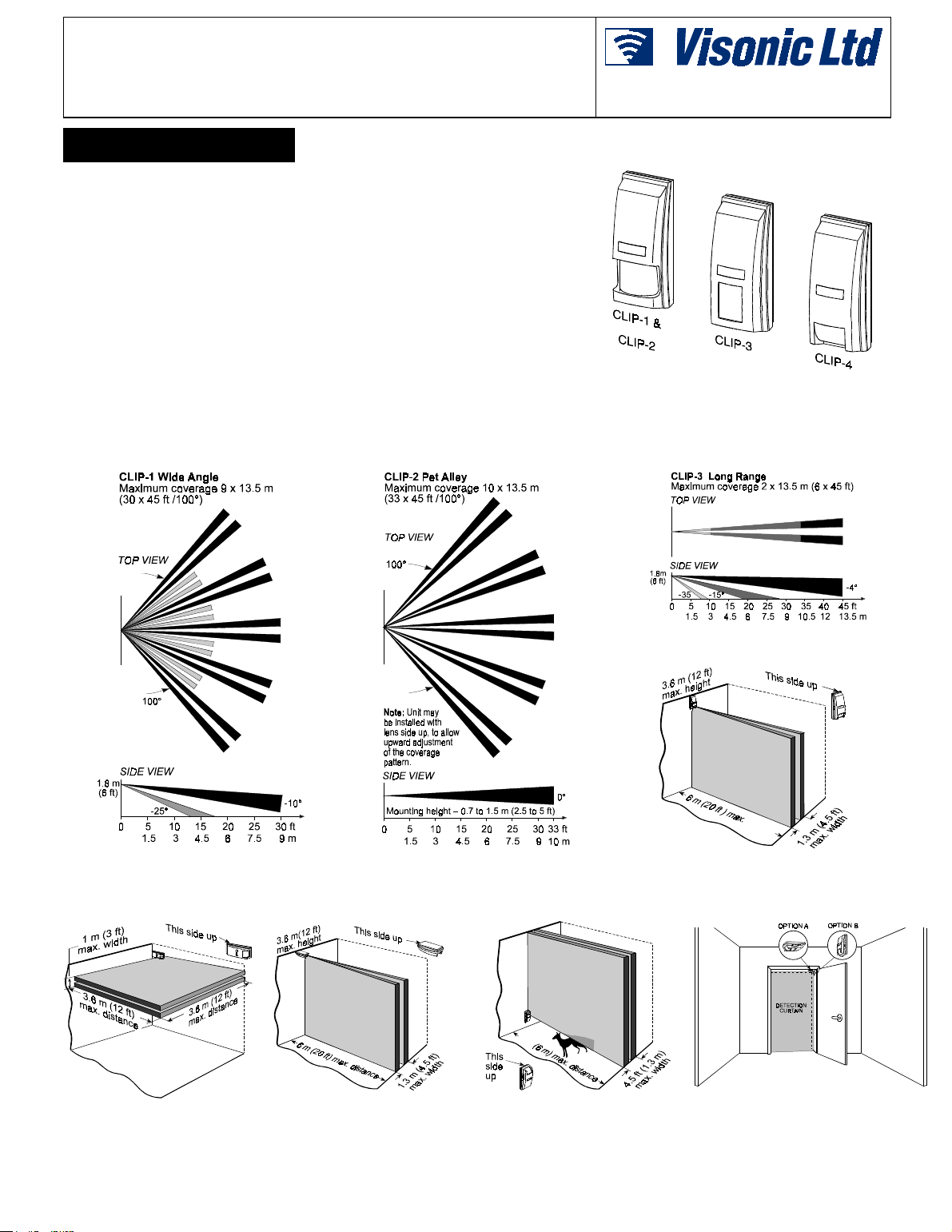
There is a difference in shape between the four models (Figure 1). Detailed
specificat ions of the lenses employed in each model ar e given below. Detection
patterns of the CLI P -1, 2 and 3 are given in Figures 2, 3, and 4, respectively
Mounting alternatives and c over age patt er ns f or the CLI P- 4 sol i d cur t ain model are
shown in Figures 5 through 9.
Installation Instructions
Figure 1. The CLIP Models
Figure 2. The CLIP-1 Coverage Pattern
Figure 3. The CLIP-2 Coverage Pattern
Figure 4. The CLIP-3 Coverage Pattern
Figure 5. CLIP-4: Wall-Mount Curtain
Figure 6. CLIP-4:
Ceiling-Mount Curtai n
Figure 7. CLIP-4: Overhead
Curtain
Figure 8. CLIP-4: Curtain with
Pet Alley
Figure 9. CLIP-4: Mounting on
Internal Doorfr ame for Passage
Detection
DE1161 1
Page 2
63(&,),&$7,216
OPTICAL
Detection Pattern: 4 versions are available, each with a dif ferent
detection patter n.
CLIP-1: 100° Wi de Angle. Provides 9 dual beams in 2 detec tion
layers, with maximum cover age area of 9 x 13.5 m (30 x 45 ft).
CLIP-2: 100° Pet Alley. Provides 5 dual beams in a single
detection layer, with maximum coverage area of 10 x 13.5 m (33
x 45 ft).
CLIP-3: Long Range. Provides a long range cor ridor barrier wi th
two fill-in beams below the long beam. The maximum coverage
range is 13.5 m (45 ft).
CLIP-4: Curtain. Pr ovides a sol id c urt ain wi th maximum c over age
area of 3.6 x 6 m (12 x 20 ft).
Adjustment: Vertical 0° to -12° cali brated scale.
ELECTRICAL
Voltage: 10 to 16 VDC.
Current: 12.5 mA at 12 VDC.
Alarm Output: Normally c losed (f ail-saf e) contac ts. 18Ω resistor
in series with contacts. Rating - 0.1A resistive /24 VDC.
Tamper Output: Nor m ally closed. Rating 0.1A resistive /24 VDC.
Alarm Period: 2-5 seconds.
,167$//$7,21
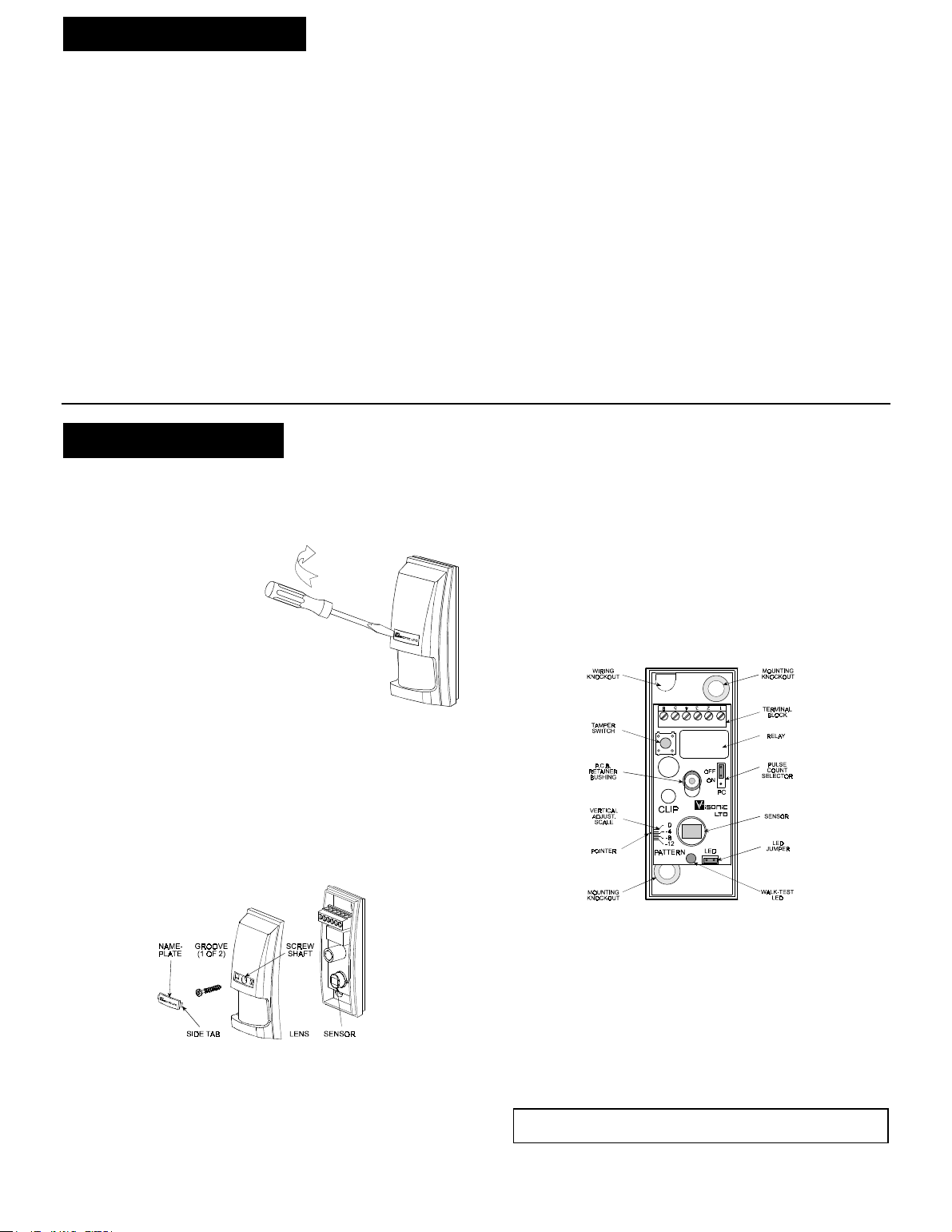
&/,38QLW'LVDVVHPEO\
The screw which att aches the front cover to the bas e is hidden
behind the miniature plastic nameplate at the front.
A. Removing the Front Cover
Remove the name-plate from
its recess by inserting the
blade of a small screwdriver
into one of the narrow gaps at
the sides, as s hown in Figure
10. Lever carefully s ide-ways,
until the name-plate arches
slightly out and snaps free (do
not let it fly free and get lost).
Retain the nameplate and
loosen the screw within the
inner shaft (see Figure 11).
Remove the cover carefully, t o
avoid dropping the screw.
B. Installing the Front Cover
Carefully fit the front cover onto the bas e, with the l ens in fr ont of
the sensor, insert the screw into its shaft and tighten it well.
Place the nameplate correctl y, and insert its left-si de tab into the
left-side groove. Pr ess the free edge of the namepl ate sideways
with your finger against the already seated left edge, until the
name plate arches sl ightly out ward. Then pres s the r ight s ide t ab
into the right s ide groove, making sure it snaps shut.
Figure 10. Disassembly of the
CLIP PIR
Pulse Counter: 2 position selector, 1 or 2 pulse operation
(alternate polarity).
LED: Walk Test enabled or disabled with internal link.
Detector: Dual-element low noise pyroelectric detector.
MOUNTING
CLIP-1, 2 and 3: Wall mounting.
CLIP-4: Wall or ceiling mounting.
Mounting Height:
CLIP-1 and 3: Up to 2.4 m (8 ft).
CLIP-2: 0.7 to 1.5 m (2.5 to 5 ft).
CLIP-4: Up to 3.6 m (12 ft).
ENVIRONMENTAL
Operating Temperatur e: -10°C to 50°C (14°F to 122°F).
Storage Temperature: -20°C to 60°C (-4°F to 140°F).
RFI Protection: > 20 V/ m to 1000 MHz.
PHYSICAL
Dimensions (H x W x D): 70 x 28 x 25 mm. (2-3/ 4 x 1-1/ 4 x 1 in) .
Weight: 25 g. (0.9 oz).
Color: White.
intruder will cross the coverage pattern.
B. The maximum mounting height for CLIP -1 and CLIP-3 is 2. 4
m(8 ft). An acc urate adjust ment table – Tabl e 1 – serves as a
guide which provides the recommended vertical adjustment
with respect to detection range and mounti ng height.
C. When mounting the CLIP- 4 on the ceiling (see Figur e 6), the
ceiling height must not exceed 3.6 m (12 f t). The maximum
detection distance from the detector is 6 m (20 ft), and the
curtain width at t hat distance is 1. 3 m (4.5 ft).
D. Alternatively, t he pet alley model CLI P-2 may be ins talled in a
lens-up position. This will allow upward adjustment of the pet
alley, so that the lower part of the detection pattern will be
parallel to the floor.
Figure 12. Inside the CLIP
E. CLIP is extremely immune to air turbulence and RFI.
However, to minimize possible false alarms, it is highly
recommended to avoid aiming the detector at heaters,
sources of li ght, or windows s ubjected to direc t sunlight. Also
avoid running wiring close to high power electrical cables.
F. Remove the front cover as instructed in Section 3, Para. A.
Figure 11. Disassembly of the CLIP PIR
0RXQWLQJ
The CLIP-1 through CLIP-3 are des igned for mounting di rec tly on
walls (surface mounting). The regular wall mounting position is
with the lens down. The CLIP-4 solid curtain model may be
mounted in various positions on walls, ceilings and door frames
(Figures 5 through 9).
A. Select the mounting locati on so that the expected motion of an
G. Mount the base with the PCB intact at the location and height
selected for optimum coverage.
Use the two mounting knockouts at the back of the base
(Figure 12). Carefully sl ide the PCB up to gain access to the
bottom mounting knockout which is partly hidden.
Be sure to do so by grabbing the terminal block with two
fingers. Do not exert force on any other component!
H. Always install the unit on a firm and stable surface, and
assure that there are no moving objects within its field of view.
2 DE1161
Page 3

:LULQJ
To route wires int o the detector, use the wi ring knock out located
at the top left of the unit base (Figure 12).
Since the knockout is
angular, the wiring may be
inserted from behind the
base or from the top, as
required for the particular
installation. Refer to Fig. 13
Figure 13. Terminal Block Wiring
and connect wires to the terminal block in the followi ng order.
A. Connect ter minals 5 and 6 – the tamper N.C. t erminals – t o a
normally closed 24-hour prot ective loop of the control panel.
The tamper contacts will open when t he cover is removed.
B. Connect terminals 1,2 (the relay N.C. terminals ) to a normally
closed protect ive loop of t he control panel. The r elay cont acts
will open when motion is detected or dur ing power loss.
C. Connect terminals 3 (–) and 4 (+) t o a 10 to 16 Volt DC power
source, making sure that the polarity is correct. It is
mandatory that the power supply have battery backup.
Current drain of each CLIP PIR is approximately 12.5 mA.
9HUWLFDO$GM XVW P HQW
The vertical adjust ment scale (pri nted on the lower lef t corner of
the PCB) and the plasti c pointer on the base indicate i n degrees
the approximate vertical angl e between the horizontal line of the
unit and the upper detect ion layer.
Table 1 gives the recommended scale adjustment for various
combinations of mounting height and coverage distance. The
scale permits fast, easy pattern adjustment from 0° to -12°
downward according to the installation height and the required
coverage range.
The sensors are preset to -4°. To change the vertical pattern
adjustment, remove the cover, hold the terminal block with two
fingers and sli de the PCB up or down to the desired angle.
Caution! CLIP is a delicate device due to its small size. Do
not exert force on any component other than the term inal
block. Failure to observe this may damage the detector.
The friction on the PCB should be enough to maintain t he new
position until you remount the front cover and tight en the screw.
Tightening the screw exerts additional pressure on the plastic
bushing which binds the p.c. board to the back cover.
Note: Since the beam width increases with distance from the
detector, an inverted (lens up) installation of the CLIP-2 (Pet Alley
model ) is advisable in c ertain cases. Set t he scale between -4°
and -6°, to obtain the des ired pet alley height.
Table 1. Vertical Adj usting Scale
&/,33XOVH&RXQWHU
The CLIP PIRs are equipped with a programmable puls e counter
which can be set to c ount 1 or 2 pulses wit h alternate polarity,
before activati ng the alarm relay. To set t he pulse counter, place
the jumper at the desired setting (ON or OFF).
ON (2 pulses). This s etting pr ovides impr oved protec tion against
false alarms c aus ed by all types of envir onmental dis t urbanc es . I t
should only be used in temper ature controlled locations (less than
30°C / 86°F).
OFF (1 Pulse). This set ting ac tuall y disabl es the pul se c ounter. It
should be used when it is necess ary to activate an alar m on the
first detected pulse, or in high security installations, when fast
"catch" performance is of greatest importance.
:DON7HVWLQJ
A. Apply 12 VDC power and allow five minutes for the unit to
warm up and stabilize.
B. Adjust the vertic al calibration angl e according to Table 1.
C. Set the pulse counter per Para. 3.5 above.
D. Walk-test the range and coverage area by walking slowly
across the field of view (i n opposite directions) and observe
the LED. The LED lights up whenever you enter or exit a
sensitive beam. Allow 5 seconds between each test for the
unit to stabilize.
E. After tes ti ng, the LED can be dis abled t o pr event unaut hori zed
persons from tracing the coverage pattern. To disable the
LED, remove the LED jumper from its position across t he 2
pins and install it on one of the pins to pr event losing it.
Note: The range and coverage ar ea should be checked at l east
once a year. To ass ure proper continuous functioning, the user
should be instruc ted to perform a walk test at the far end of the
coverage pattern t o assur e an alarm signal pr ior to each ti me the
alarm system is armed.
:$55$17<
:$55$17<
Visonic Ltd. and/or its subsidiaries and its affiliates ("the Manufacturer") warrants its
products hereinafter referred to as "the Product" or "Products" to be in conformance with
its own plans and specifications and to be free of defects in materials and workmanship
under normal use and service for a period of twelve months from the date of shipment by
the Manufacturer. The Manufacturer's obligations shall be limited within the warranty
period, at its option, to repair or replace the product or any part thereof. The Manufacturer
shall not be responsible for dismantling and/or reinstallation charges. To exercise the
warranty the product must be returned to the Manufacturer freight prepaid and insured.
This warranty does not apply in the following cases: improper installation, misuse,
failure to follow installation and operating instructions, alteration, abuse, accident or
tampering, and repair by anyone other than the Manufacturer.
This warranty is exclusive and expressly in lieu of all other warranties, obligations or
liabilities, whether written, oral, express or implied, including any warranty of
merchantability or fitness for a particular purpose, or otherwise. In no case shall the
Manufacturer be liable to anyone for any consequential or incidental damages for breach
of this warranty or any other warranties whatsoever, as aforesaid.
This warranty shall not be modified, varied or extended, and the Manufacturer does not
authorize any person to act on its behalf in the modification, variation or extension of this
warranty. This warranty shall apply to the Product only. All products, accessories or
attachments of others used in conjunction with the Product, including batteries, shall be
covered solely by their own warranty, if any. The Manufacturer shall not be liable for any
damage or loss whatsoever, whether directly, indirectly, incidentally, consequentially or
otherwise, caused by the malfunction of the Product due to products, accessories, or
attachments of others, including batteries, used in conjunction with the Products.
VISONIC LTD. (ISRAEL): P.O.B 22020 TEL-AVIV 61220 ISRAEL. PHONE: (972-3) 645-6789, FAX: (972-3) 645-6788
VISONIC INC. (U.S.A.): 10 NORTHWOOD DRIVE, BLOOMFIELD CT. 06002-1911. PHONE: (860) 243-0833, (800) 223-0020 FAX: (860) 242-8094
VISONIC LTD. (UK): UNIT 1, STRATTON PARK, DUNTON LANE, BIGGLESWADE, BEDS. SG18 8QS. PHONE: (01767) 600857 FAX: (01767) 601098
VISONIC LTD. 1998 CLIP D-1161-0 NEW: DE1161- (REV. 1 ,4/98).
The Manufacturer does not represent that its Product may not be compromised and/or
circumvented, or that the Product will prevent any death, personal and/or bodily injury
and/or damage to property resulting from burglary, robbery, fire or otherwise, or that the
Product will in all cases provide adequate warning or protection. User understands that a
properly installed and maintained alarm may only reduce the risk of events such as
burglary, robbery, and fire without warning, but it is not insurance or a guarantee that such
will not occur or that there will be no death, personal damage and/or damage to property
as a result.
The Manufacturer shall have no liability for any death, personal and/or bodily injury
and/or damage to property or other loss whether direct, indirect, incidental,
consequential or otherwise, based on a claim that the Product failed to function.
However, if the Manufacturer is held liable, whether directly or indirectly, for any loss or
damage arising under this limited warranty or otherwise, regardless of cause or origin, the
Manufacturer's maximum liability shall not in any case exceed the purchase price of the
Product, which shall be fixed as liquidated damages and not as a penalty, and shall be the
complete and exclusive remedy against the Manufacturer.
Warning: The user should follow the installation and operation instructions and among
other things test the Product and the whole system at least once a week. For various
reasons, including, but not limited to, changes in environmental conditions, electric or
electronic disruptions and tampering, the Product may not perform as expected. The user
is advised to take all necessary precautions for his /her safety and the protection of
his/her property.
6/91
DE1161 3
 Loading...