

Page 1
&/:%
Wireless Keypad
,1752'8&7,21
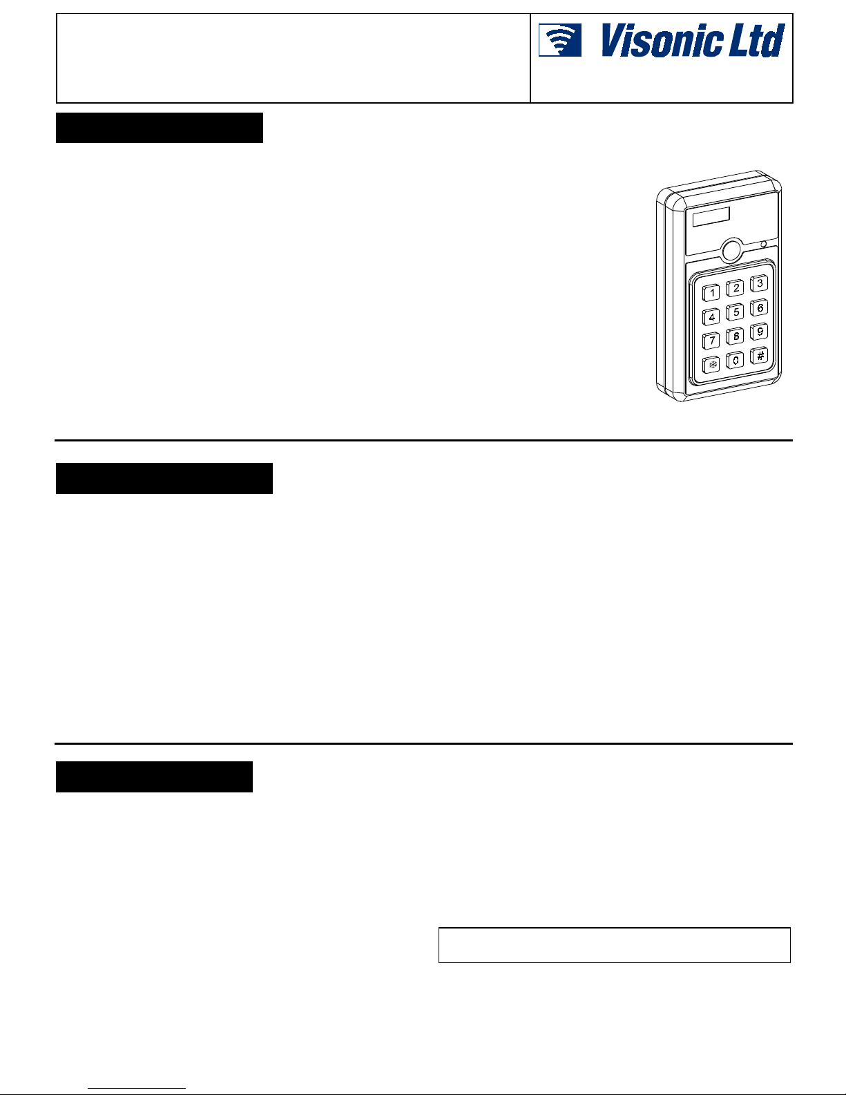
The CL-4WB is a digital, wireless multi-function keypad unit,
especially suit able for electronic security syst ems. It is designed
to transmit a radio frequency (RF) signal to a remote r eceiver as
soon as the user enters a pre-pr ogrammed, 4-di git sec ret acc ess
code.
Applications of the CL-4WB include: remote arming and
disarming of c ontrol panels, operating doors , gates, etc. The unit
can be easily incorporated into virtually any new or existing
Visonic Ltd. wireless system.
The transmitted RF signal consists of two digital codes - a
SYSTEM code and a CHANNEL code, which perform the
following functi ons:
• The SYSTEM code serves as a password – the remote
receiver ignores RF signals other than the correctly coded
ones. System code matching between the CL-4WB and the
remote receiver is obtained by selecti ng identical settings on
an 8-position CODE swi t ch i n bot h unit s. I t i s poss i ble t o sel ec t
256 different system codes (para. 3.3).
• The CHANNEL code determines which one of the remote
receiver
63(&,),&$7,216
Installation Instructions
outputs will be activated by the
transmitted RF s ignal. This code
is selected by presetting the
CL-4WB's 4-position
"CHANNEL" selector (par a. 3.4).
"Channel 2" code is dedic ated to
tamper and PANIC alarms (a
PANIC alarm signal is
transmitted when the k and #
keys are pressed
simultaneously).
The CL-4WB is powered by a 9-volt
alkaline or lithi um battery. Its pl astic
housing is suitable for wall
mounting and opens by removal of
a single screw. A short antenna
wire extends from the bot tom of t he
case.
ELECTRICAL
Voltage: 9-volt alkaline or lithi um battery.
Keypad: 12 keys, 3 x 4 tactil e operation
Security Code: 4-digits, jumper sel ectable - 5040 dif ferent code
combinations.
Code Combinations: 5040 (t he codes are not lost due to power
failures).
Automatic Reset: 5 seconds
Panic Output: Activat ed by simultaneousl y pressing the ∗ and #
keys. Channel code 2 is transmitted as the panic signal, while
these keys remain depressed.
Tamper Switch: Normal ly closed. Channel code 2 is trans mitted
as a tamper signal, when the keypad as sembl y is separ ated f rom
the back cover.
Visual Indications: Red LED lights during transmission,
provided that the battery volt age exceeds 7.5 Volt s. The indi cator
is inhibited during trans mission of the tamper and panic signal s
,167$//$7,21
23(5$7,21
The CL-4WB is triggered int o transmission by a 4-digit s ecurity
code entered by the user on its fr ont panel keypad. The instal ler
programs the selected security code by linking a few on-board
terminals. This pr ogramming met hod ensures that t he code is not
lost due to power fai lures or electrical dis turbances.
To initiate trans mission, the user is required to enter the correct
(programmed) four di git code in proper s equence within about 5
seconds.
Should the user take more time than permitted, or if the user
makes an error whil e enteri ng a code, an automat ic res et r esul ts,
requiring the user to wait a f ew seconds and t hen repeat entry of
the security code. This feature virtually prevents unauthorized
(channel 2 code).
System Code: 8-bit digital word, 256 combinations, pulse width
modulation.
Channel: 4 switc h-selectable channel codes: 1, 2, 3 and 4.
Frequency (MHz): 315, 304, 404, 418, 433.92, 224.7 or other
frequencies according to local requirements.
ENVIRONMENTAL
For indoor use only.
Operating Temperatur e: 0°C t o 50°C (32°F to 122°F).*
Storage Temperature: - 20° to 60°C (-4°F to 140°F).
* Does not apply to the battery.
PHYSICAL
Size: 110 x 63 x 25 mm (4 1/3 x 2 1/2 x 1 in.)
Weight: 110 g. (3.5 oz).
Mounting: Surface-mounted
Color: White.
people from defeating the code by randomly pressing keypad
buttons.
Once the correc t code has been entered, the keypad's transmitter
operates for 2 - 4 seconds. A front panel LED lights during
transmission, indicating the battery status (provided that the
battery voltage is above 7.5 VDC). If the LED does not light
during transmis sion, the battery must be replaced immediately.
Note: For security reasons, the LED does not light when the
tamper alarm or panic alarm are transmitted (Channel 2).
CAUTION: The keypad is only for indoor use
DO NOT INSTALL OUTDOORS!
.
DE4021 1
Page 2
,QVWDOODWLRQ3URFHGXU H
A. Remove the screw
from the front of the
unit. Punch out at
least two diagonally
opposed mounting
knockouts. Mark the
wall and drill holes
as required. Use wall
inserts and scr ews to
mount the unit fir m ly.
B. Select the SYSTEM
code (para. 3.3).
C. Select the CHANNEL
code (para. 3.4).
D. Program the user's
secret access code
(para. 3.5).
E. Snap the battery clip
onto the 9-volt battery terminal s .For long life, use alkaline or
lithium battery.
F. Test the unit as ins tructed in para. 3.6.
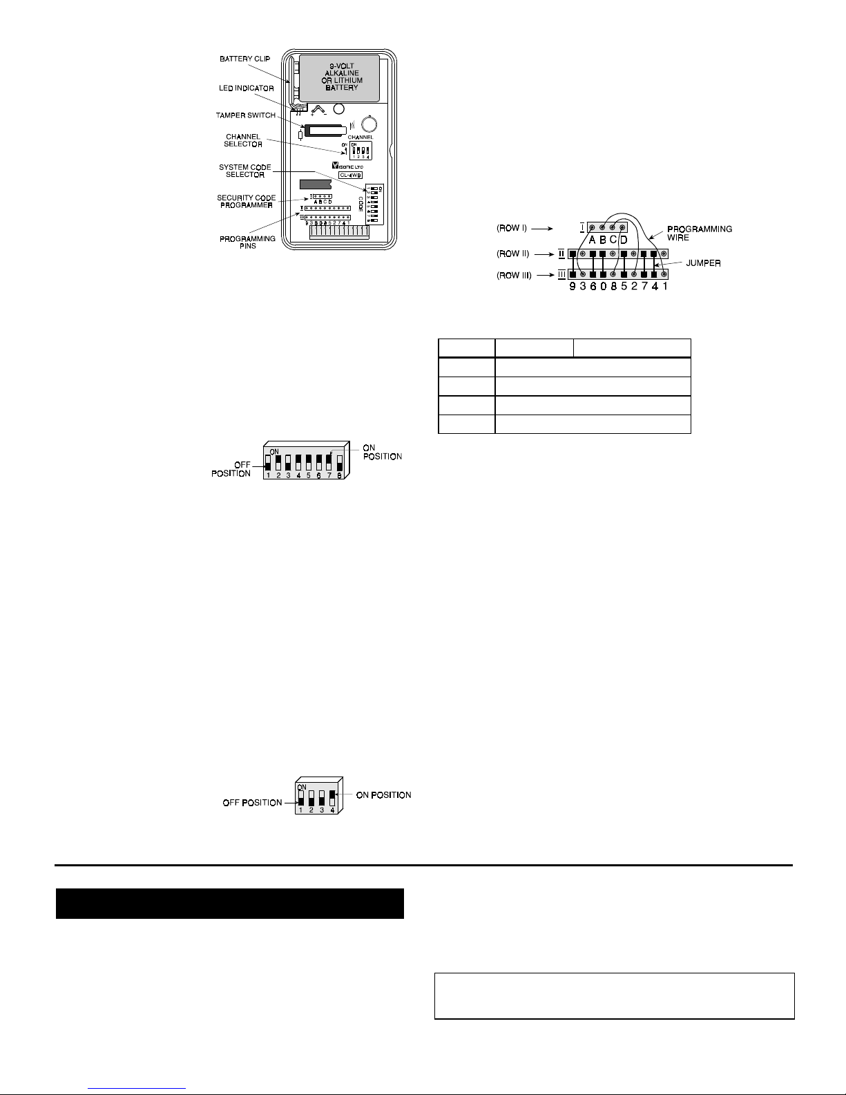
Figure 1 - Components Layout
6\VWHP&RGH6HOHFWLRQ
The CL-4WB has an 8-position DIP switch, marked CODE, as
shown in Figures 1 and 2. Each switc h (1 through 8) may be set
to ON or OFF, to create a uni que digital sys tem code t hat diff ers
from that used by other wireless sys tems that may be operating
in the vicinit y.
Use a ball-point pen to
set each switch lever to
match the system code
setting of the remote
companion receiver.
Note: The code combination 2, 4, 5, 6, 7 ON / 1, 3, 8 OFF is a
factory test code which must not be us ed. Also avoid codes which
are often used: all k eys ON, all keys OFF or alternating ON/OFF
settings.
Figure 2 - System Code Select or
&KDQQHO&RGH6HOHFWLRQ
The CL-4WB has a bui lt-in multichannel trans mitter that can be
set to transmit one of 4 different channel codes to activate
different output s in the remote receiver.
The channel selector consi sts of a 4-posit ion DIP s witc h, mark ed
CHANNEL, as shown in Figures 1 and 3. The channel code
transmitted by the CL-4WB is selected by switching the
corresponding c hannel key (1, 2, 3 or 4) to ON.
Select the channel acc ording to the remot e receiver's output you
wish to be activated by the CL-4WB.
Note: Since channel 2 code is transmitted automatically upon
occurrence of Tamper and Panic alarms, refr ain from selec ting it
for other purposes.
It is also possible to select
more than one channel for
simultaneous transmission,
which will activate the
corresponding channel
outputs at the receiver.
Figure 3 - Channel Code Select or
with Channel 4 Selected.
3URJUDPPLQJ WKH 8VHUV 6HFXULW\
$FFHVV&RGH
Programming of the user's 4-digit security access code is
accomplished by linki ng pins in ROW I to the appropri ate pins in
ROW III (the digits row) in accordance with the desir ed code ( s ee
Figure 4). Use the 4 wires supplied with t he keypad.
Note: Each unprogrammed pin i n ROW III (pins 0, 4, 5, 6, 7, 9 in
Figure 4) must be bridged to the pin just above it in ROW II, using
the jumpers supplied with the keypad. For convenience, it is
preferable to carry out this bridging operation first and then
connect row I pins to the remaining row III pins in the correct
order.
Figure 4. Programming Access Code 3128
EXAMPLE: CODE 3128
Digit ROW I ROW III
1st
2nd
3rd
4th
Pin A →
Pin B →
Pin C →
Pin D →
Connect to Pin 3
Connect to Pin 1
Connect to Pin 2
Connect to Pin
7HVWLQJ
A. Carefully position the keypad assembly over the rear cover.
Secure both halves of the case together using the screw.
B. Have someone observe the remote receiver and report its
response to you during the following steps.
C. Operate the t ransmitter by entering t he correct acces s code.
Verify that the front panel LED lights, indicati ng good battery
condition.
D. The receiver LED should light, indicating detection of the
transmitted RF s ignal.
E. Verify activat ion of the c hannel output r elay(s) at the recei ver,
in accordance with the setting of the CL-4WB's CHANNEL
switch.
F. While monitoring receiver channel 2 (tamper and PANIC
channel), separate the CL-4WB keypad assembly from the
back cover, t hus activating the tamper switch. Verif y that the
tamper signal is received c ontinuously at receiver channel 2,
as long as the tamper switch remains activated.
G. Replace the CL-4WB keypad assembl y over the back cover
and attach with the screw. Push the round plastic cap
supplied in the package over the head of the screw. Verify
that channel 2 output at the receiver r estores (r everts to the
standby state).
H. While monitoring receiver channel 2 (tamper and PANIC
channel), simultaneously press the k and # keys, thus
activating the PANIC alarm. Verify that the PANIC signal is
received continuously at receiver channel 2, as long as the
two keys remain pr essed.
0,6&(//$1(286&200(176
Visonic Ltd. wi reless syst ems are reliable and are t ested to high
standards. However, due to t heir low t rans mi tt ing power ( r equir ed
by FCC regulations), there are some lim itations to be c onsidered:
A. Receivers may be blocked by radio signals occurring on or
near their operating frequencies, regardless of the code
selected.
B. A receiver can only respond to one transmitted signal at a
time.
2 DE4021
C. W ireless equipment should be tes ted regularly (at leas t once
a week) to determine if there are s ources of inter ference and
to protect against faults.
WARNING! Changes or modifications to this unit not expressly
approved by the party responsible for compliance could void t he
user's author ity to operate the equipment.
Page 3

:$55$17<
:$55$17<
Visonic Ltd. and/or its subsidiaries and its affiliates ("the Manufacturer") warrants its
products hereinafter referred to as "the Product" or "Products" to be in conformance with
its own plans and specifications and to be free of defects in materials and workmanship
under normal use and service for a period of twelve months from the date of shipment by
the Manufacturer. The Manufacturer's obligations shall be limited within the warranty
period, at its option, to repair or replace the product or any part thereof. The Manufacturer
shall not be responsible for dismantling and/or reinstallation charges. To exercise the
warranty the product must be returned to the Manufacturer freight prepaid and insured.
This warranty does not apply in the following cases: improper installation, misuse,
failure to follow installation and operating instructions, alteration, abuse, accident or
tampering, and repair by anyone other than the Manufacturer.
This warranty is exclusive and expressly in lieu of all other warranties, obligations or
liabilities, whether written, oral, express or implied, including any warranty of
merchantability or fitness for a particular purpose, or otherwise. In no case shall the
Manufacturer be liable to anyone for any consequential or incidental damages for breach
of this warranty or any other warranties whatsoever, as aforesaid.
This warranty shall not be modified, varied or extended, and the Manufacturer does not
authorize any person to act on its behalf in the modification, variation or extension of this
warranty. This warranty shall apply to the Product only. All products, accessories or
attachments of others used in conjunction with the Product, including batteries, shall be
covered solely by their own warranty, if any. The Manufacturer shall not be liable for any
damage or loss whatsoever, whether directly, indirectly, incidentally, consequentially or
otherwise, caused by the malfunction of the Product due to products, accessories, or
attachments of others, including batteries, used in conjunction with the Products.
The Manufacturer does not represent that its Product may not be compromised and/or
circumvented, or that the Product will prevent any death, personal and/or bodily injury
and/or damage to property resulting from burglary, robbery, fire or otherwise, or that the
Product will in all cases provide adequate warning or protection. User understands that a
properly installed and maintained alarm may only reduce the risk of events such as
burglary, robbery, and fire without warning, but it is not insurance or a guarantee that such
will not occur or that there will be no death, personal damage and/or damage to property
as a result.
The Manufacturer shall have no liability for any death, personal and/or bodily injury
and/or damage to property or other loss whether direct, indirect, incidental,
consequential or otherwise, based on a claim that the Product failed to function.
However, if the Manufacturer is held liable, whether directly or indirectly, for any loss or
damage arising under this limited warranty or otherwise, regardless of cause or origin, the
Manufacturer's maximum liability shall not in any case exceed the purchase price of the
Product, which shall be fixed as liquidated damages and not as a penalty, and shall be the
complete and exclusive remedy against the Manufacturer.
Warning: The user should follow the installation and operation instructions and among
other things test the Product and the whole system at least once a week. For various
reasons, including, but not limited to, changes in environmental conditions, electric or
electronic disruptions and tampering, the Product may not perform as expected. The user
is advised to take all necessary precautions for his /her safety and the protection of
his/her property.
6/91
VISONIC LTD. (ISRAEL): P.O.B 22020 TEL-AVIV 61220 ISRAEL. PHONE: (972-3) 645-6789, FAX: (972-3) 645-6788
VISONIC INC. (U.S.A.): 10 NORTHWOOD DRIVE, BLOOMFIELD CT. 06002-1911. PHONE: (860) 243-0833, (800) 223-0020 FAX: (860) 242-8094
VISONIC LTD. (UK): UNIT 1, STRATTON PARK, DUNTON LANE, BIGGLESWADE, BEDS. SG18 8QS. PHONE: (01767) 600857 FAX: (01767) 601098
VISONIC LTD. 1998 CL-4WB D-4021-0 NEW : DE4021- (REV. 1, 4/98)
DE4021 3
 Loading...