

Page 1
DE6271 1
AXS
AXSAXS
AXS-10
-10-10
-10 PRO
PRO PRO
PRO
Single-Door Proximity Access Control System
Installation Instructions
1111. INTRODUCTION
. INTRODUCTION. INTRODUCTION
. INTRODUCTION
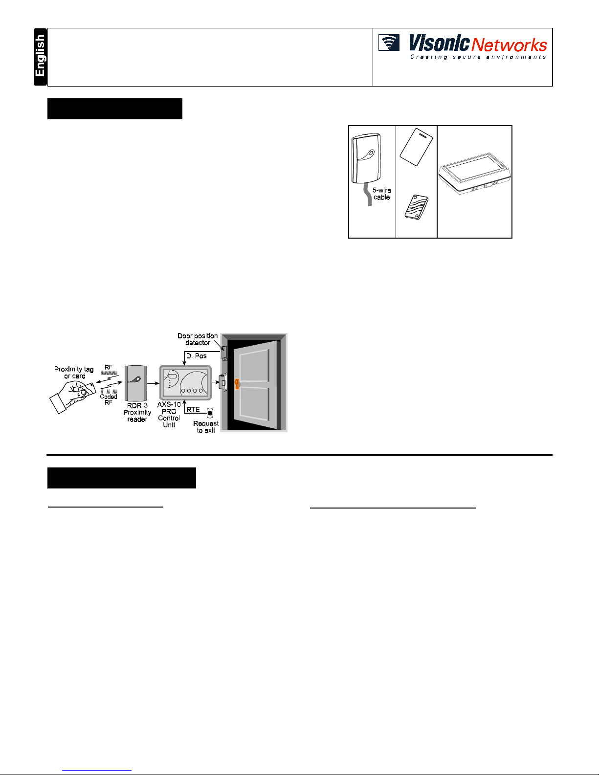
The Visonic Networks AXS-10 PRO is an electronic access control
system designed for a single access point, such as a main door in an
apartment building or individual office doors. The system control unit
relay activates a lock or electromagnetic strike lock (EMS), when a
valid proximity key (tag or card) is presented to the reader located
outside the protected area.
The use of a proximity (non-contact) key makes the installation of the
AXS-10 PRO system an attractive possibility in harsh environments
and in places with poor lighting conditions. The proximity keys are
totally sealed and are wear resistant. The reader reads the key’s ID,
whenever the key is presented.
A second proximity reader may be connected to the AXS-10 PRO to
control both sides of a door.
The separate weatherproof readers provide added security and
flexibility allowing outdoor or indoor installation.
The AXS-10 PRO control unit (see figure 1) includes a 3-digit display,
3 visual indicators (LEDs) and 4 buttons. An internal proximity reader
located in the upper right corner of the control panel allows fast and
easy programming of access keys. The buttons are used for entering
the password and for programming the unit.
AXS-10 PRO controllers can be networked (see par. 4.4.).
Figure 1 - System Functional Presentation
RDR-3
Proximity
Reader
CRD-1
Prox. Card
TAG-1
Prox. Tag
AXS-10 PRO
Control Unit
Figure 2 - System Components
The AXS-10 PRO has a memory capacity of 300 keys. Adding keys
simply involves presenting new keys to the controller while the system
is in ADD mode.
The user can delete keys in the DELETE mode by presenting them to
the reader or, if a tag/card is not available, by typing in its number (the
same one that appears when adding the key).
When the system is in TOGGLE mode, presenting a valid tag
arms/disarms an alarm system or activates/deactivates an electrical
device (such as an air conditioner).
The AXS-10 PRO kit includes:
• AXS-10 PRO controller
• RDR-3 proximity reader with 1m (3 ft) 5-wire cable
• Installation instructions
• User guide
• Control unit base template, for wall installation
Additional tools and equipment that may be needed:
• Proximity tags or cards (ordered separately)
• Power supply for the controller - 12V AC/DC
• Electromagnetic strike lock (EMS) unit
• RTE (request-to-exit) push button or PIR, if required.
2222. SPECIFICATIONS
. SPECIFICATIONS. SPECIFICATIONS
. SPECIFICATIONS
AXS-10 PRO CONTROLLER
Power Input: 9-12V AC/DC
Max Current Consumption: 150 mA (excluding EMS current)
Memory Capacity: 300 proxy tags/cards
Event Memory Capacity: 350 events (time/date stamped)
Output Relay Contact Rating: 1A Max. continuous current
Display: 3 x 7 segments and 3 LEDs
Operating Temperatures: 0°C to 50°C (32°F to 122°F)
Dimensions (L x W x D): 150 x 105 x 35 mm (5-7/8 x 4-1/8 x 1-3/8 in.)
Color: Dark gray
Weight: 250g
RDR-3 EXTERNAL PROXIMITY READER
Indicators: Tricolor LED (Green, Red, Amber)
Tag Reading Range: 50-100 mm (2-4 in.)
Frequency: 125 kHz
Tag Code Possibilities: 10
12
possible combinations
Dimensions (L x W x D): 116 x 70 x 16.8 mm (4-1/2 x 2-3/4 x 5/8 in.)
Weight: 121.5 g (4.3 oz)
Operating Temperatures: -20°C to 50°C (-4°F to 122°F)
Cable
(to RDR-3 control unit) maximum length: less than 10 meters
(33 ft.)
Color: Dark brown
Page 2
2 DE6271
3333. INSTALLATION
. INSTALLATION. INSTALLATION
. INSTALLATION
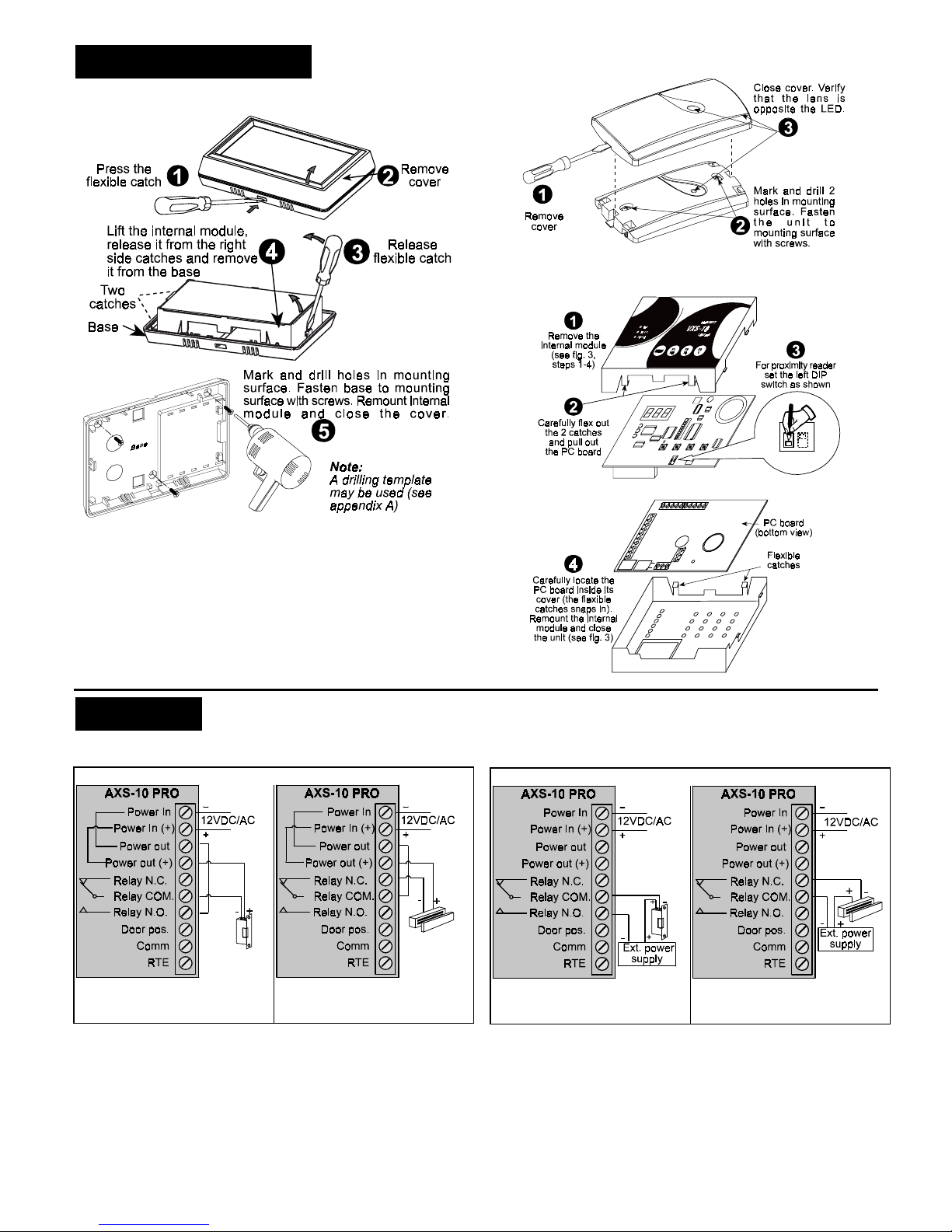
3.1 Controller Unit Installation
Figure 3 - Control Unit Installation
3.2 Proximity Reader Installation
Caution: Do not install the RDR-3 on a metal surface or on a metal
door frame, since this decreases the key reading range significantly.
If you have to install the reader on a metal surface, use a spacer plate
so that the reader will be at least 1 cm (3/8 in.) away from the metal.
You may use RDR-BACK which is an optional spacer plate made
specifically for this purpose.
When installing two readers, you may install them in close proximity
to each other.
Figure 4 - Proximity Reader Installation
3.3 Setting DIP Switch
Figure 5 - DIP Switch Setting
4444. WIRING
. WIRING. WIRING
. WIRING
4.1 Electromagnetic Strike Wiring
Electro-Magnetic Locks Powered by AXS-10 PRO
A.Connecting Electro-magnetic
lock that opens the door when
power is supplied
B.Connecting Electro-magnetic
lock that opens the door when
power is disconnected
Electro-Magnetic Locks Powered by an External Power Supply
C.Connecting Electro-magnetic
lock that opens the door when
power is supplied
D.Connecting Electro-magnetic
lock that opens the door when
power is disconnected
Page 3

DE6271 3
4.2 RTE and Door Position Wiring
Figure 6 - Connecting RTE and Door Position Inputs
4.3 Proximity Readers Wiring
Figure 7 - Connecting One Proximity Reader
Figure 8 - Connecting Two Proximity Readers
4.4 Using AXS-10 PRO Controllers As a Network
Up to four AXS-10 PRO controllers can be networked, for use of up to
300 users (keys). Such a network, called a site, can be connected to a
remote PC via an external telephone modem. Up to 5 site can be
connected to the PC in this way.
The maximum distance between adjacent AXS-10 PRO controllers
should not exceed 25 meter (75 ft.). To increase the distance (with
1200m increments), use SHM-1 modem (refer to the SHM-1 manual).
A AXS-10 PRO network enables the installer / user to control all the 4
controllers from one controller.
In such a configuration, every one of the 4 controller keys enables
unlocking each of the network 4 doors.
AXS-10 PRO network with PC and AXSoft-10M software provides:
• Real time recording and display of system events on the PC
screen.
• Reports on users and events can be sent to a local or network
printer.
• The system operator can program the unlocking duration (in
seconds) of the network doors.
• Adding and deleting keys can be done easily in the organization
security office, including adding user information.
TXD
Gnd
RXD
External
modem
AXS-10 PRO #1
TXD
Gnd
RXD
TXD
Gnd
RXD
TXD
Gnd
RXD
AXS-10 PRO #2 AXS-10 PRO #3 AXS-10 PRO #4
Figure 9 - AXS-10 PRO Network
AXS-10 PRO #1 AXS-10 PRO #2 AXS-10 PRO #3 AXS-10 PRO #4
from TXD of AXS-10 PRO#4
to RXD of AXS-10 PRO #1
GND (Black)
RS-232
TXD
Gnd
RXD
Gnd
Gnd
Gnd
TXD TXD TXD
RXD RXD RXD
Figure 10 - AXS-10 PRO Network with PC
Page 4

4 DE6271
5. PROGRAMMING
Note: While the system is in one of the programming modes, the
AXS-10 PRO does not operate the external reader or the relay output.
5.1 Entering Programming Menu
The AXS-10 PRO recognizes a 6-step installer password. Each step
requires pressing a single button or a combination of two buttons.
Note: The “MODE” button by itself cannot be used as the first button
of the password.
To enter the programming menu, press the “MODE” button and then
enter the factory defined installer password “F1”, “F2”, “F3”, “F1”, “F2”,
“F3”.
Notes
1 . It is recommended to change the password during installation
(see par. 5.6).
2 . Inactivity for more than 10 seconds causes AXS-10 PRO to exit
the programming menu and revert to normal operation.
5.2 Setting The Master Key
The AXS-10 PRO has one master key. The installer needs to assign
one of the proximity keys (tag or card) as a master key and program it
into the controller memory. To assign a master key:
• Press the “Mode” button.
• Enter installer password. The green “ADD” LED starts flashing.
• Press “MODE” a few times until the display shows: ”S0”. The
system is ready to read the key. Present a tag or card to the top
right corner of the controller (internal proximity reader).
• Once a key is presented, it will replace the current master key. Hold
the new key until the “SPECIAL” LED stops flashing.
• To revert to normal operation, wait 10 seconds until the AXS-10
PRO automatically exits the programming menu.
5.3 Erasing ALL User Keys
IMPORTANT: A user master key should be assigned before erasing
user keys.
• To select the ERASE ALL mode press the “MODE” button.
• Enter installer password. The green “ADD” LED starts flashing.
• Press the “MODE” button a few times until the “SPECIAL” LED
lights and the display shows “Er”.
• Present the master key to the top right corner of the controller.
• Remove the key and wait until the display blanks out.
Note: The ERASE ALL function does NOT erase the master key.
• Wait 10 seconds until the AXS-10 PRO automatically exits the
programming menu.
5.4 Setting The Door Unlock Duration
The system default unlock duration is 5 seconds The time can be set
between 1 to 99 seconds.
Note: In Toggle mode, the unlock duration is unlimited (until a valid
tag is presented).
Setting Door Unlock Period:
• Press the “MODE” button.
• Enter the installer password. The green “ADD” LED will start
flashing.
• Press the “MODE” button a few times until the “SPECIAL” LED
lights and the display shows “UL”.
• Press F2 (tens) and F3 (units) to set the unlock time in seconds.
For example, for 35 seconds press “10” three times and “1” five
times.
• The display will show the number of seconds.
• To save the unlock time and return to normal operation, present the
master key to the internal reader.
• You may press “MODE” at any time to continue without saving the
new unlock duration.
5.5 Entering/Exiting Toggle Mode
To turn the AXS-10 PRO into Toggle mode:
Setting the Unlock Duration (see par. 2.6 in the AXS-10 PRO user
guide) to 100 seconds turns the AXS-10 PRO into Toggle mode. If
the unlock time setting is less then 100 seconds, the AXS-10 PRO is
in regular mode.
To turn the AXS-10 PRO from Toggle mode into Regular mode:
Set the unlock duration to any number other than "100", then exit the
unlock duration mode.
To turn the AXS-10 PRO into Toggle mode by using master tag:
Note: When using the master card to switch to toggle mode, resetting
the power turns the AXS-10 PRO to regular mode.
• While the system is in idle mode present the master tag for 5
seconds to the RDR-3 reader.
The LED will change to green (the lock is unlocked and the
AXS-10 PRO turns into Toggle mode).
• Presenting any valid non-master key will turn the relay to lock
position.
To turn the AXS-10 PRO from Toggle mode to regular mode:
While the system is in idle mode, present the master tag for 5
seconds. The LED will blink red, which means that the AXS-10 PRO
is in regular mode.
5.6 Resetting the Installer's Password
• Gain access to the DIP switches, as shown in figure 3 (steps 1-4)
and figure 5 (steps 1-2).
• Move the rightmost switch up (password reset).
A password consists of six button keying sequence. Each press
involves either pressing a single button or a combination of two
buttons.
Press
MODE
display will show ---.
Press the following sequence:
MODE
F1
100
MODE
+
F1
100
F2
10
F3
1
F2
10
+
F3
1
• The display should show IP (Installer Password).
• Enter the new installer password (6 button presses).
The following table shows the possible combinations:
MODE
F1
100
MODE
+
F1
100
MODE
+
F2
10
MODE
+
F3
1
F2
10
F3
1
F1
100
+
F2
10
F1
100
+
F3
1
F2
10
+
F3
1
• Move the rightmost switch down (off).
• Replace the PCB and remount top cover.
5.7 Setting User Password
To set the user password, see section 2.9 in AXS-10 PRO User
Guide.
Page 5

DE6271 5
APPENDIX A: AXS-10 PRO CONTROLLER MOUNTING TEMPLATE
This device complies with the essential requirements and provisions of Directive 1999/5/EC of the European Parliament and of the Council of 9 March 1999 on radio and
telecommunications terminal equipment.
This device has been tested and found to comply with the limits for a Class B digital device, pursuant to Part 15 of the FCC Rules. These limits are designed to provide reasonable
protection against harmful interference in residential installations. This equipment generates, uses and can radiate radio frequency energy and, if not installed and used in
accordance with the instructions, may cause harmful interference to radio and television reception. However, there is no guarantee that interference will not occur in a particular
installation. If this device does cause such interference, which can be verified by turning the device off and on, the user is encouraged to eliminate the interference by one or more
of the following measures:
– Re-orient or re-locate the receiving antenna.
– Increase the distance between the device and the receiver.
– Connect the device to an outlet on a circuit different from the one which supplies power to the receiver.
– Consult the dealer or an experienced radio/TV technician.
WARRANTY
Visonic Networks Ltd. and/or its subsidiaries and its affiliates ("the Manufacturer") warrants its
products hereinafter referred to as "the Product" or "Products" to be in conformance with its
own plans and specifications and to be free of defects in materials and workmanship under
normal use and service for a period of twelve months from the date of shipment by the
Manufacturer. The Manufacturer's obligations shall be limited withi n the warr anty per i od, at its
option, to repair or replace the product or any part thereof. The Manufacturer shall not be
responsible for dismantling and/or reinstallation charges. To exercise the warranty the product
must be returned to the Manufacturer freight prepaid and insured.
This warranty does not apply in the following cases: improper installation, misuse,
failure to follow installation and operating instructions, alteration, abuse, accident or
tampering, and repair by anyone other than the Manufacturer.
This warranty is exclusive and expressly in lieu of all other warranties, obligations or
liabilities, whether written, oral, express or implied, including any warranty of
merchantability or fitness for a particular purpose, or otherwise. In no case shall the
Manufacturer be liable to anyone for any consequential or incidental damages for breach
of this warranty or any other warranties whatsoever, as aforesaid.
This warranty shall not be modified, varied or extended, and the Manufacturer does not
authorize any person to act on its behalf in the modification, variation or extension of this
warranty. This warranty shall apply to the Product only. All products, accessories or
attachments of others used in conjunction with the Product, including batteries, shall be
covered solely by their own warranty, if any. The Manufacturer shall not be liable for any
damage or loss whatsoever, whether directly, indirectly, incidentally, consequentially or
otherwise, caused by the malfunction of the Product due to products, accessories, or
attachments of others, including batteries, used in conjunction with the Products.
The Manufacturer does not represent that its Product may not be compromised and/or
circumvented, or that the Product will prevent any death, personal and/or bodily injury
and/or damage to property resulting from burglary, robbery, fire or otherwise, or that the
Product will in all cases provide adequate warning or protection. User understands that a
properly installed and maintained alarm may only reduce the risk of events such as
burglary, robbery, and fire without warning, but it is not insurance or a guarantee that
such will not occur or that there will be no death, personal damage and/or damage to
property as a result.
The Manufacturer shall have no liability for any death, personal and/or bodily injury
and/or damage to property or other loss whether direct, indirect, incidental,
consequential or otherwise, based on a claim that the Product failed to function.
However, if the Manufacturer is held liable, whether directly or indirectly, for any loss or
damage arising under this limited warranty or otherwise, regardless of cause or origin, the
Manufacturer's maximum liability shall not in any case exceed the purchase price of the
Product, which shall be fixed as liquidated damages and not as a penalty, and shall be
the complete and exclusive remedy against the Manufacturer.
Warning: The user should follow the installation and operation instructions and among
other things test the Product and the whole system at least once a week. For various
reasons, including, but not limited to, changes in environmental conditions, electric or
electronic disruptions and tampering, the Product may not perform as expected. The user
is advised to take all necessary precautions for his /her safety and the protection of
his/her property.
6/91
TECHNICAL DEPT.: 39 HAMELACHA ST. CARMIEL 20100 ISRAEL TEL: 972 4 9081115 FAX: 972 4 9081116
TECHNICAL SUPPORT EMAIL: axs_support@visonicnet.com; usa_support@visonic.com
VISONIC INC. (US): 10 NORTHWOOD DRIVE, BLOOMFIELD CT. 06002-1911. TEL: (860) 243-0833, (800) 223-0020 FAX: (860) 242-8094
VISACCESS LTD. (UK): UNIT 1, STRATTON PARK, DUNTON LANE, BIGGLESWADE, BEDS. SG18 8QS. TEL: (01767)600857 Fax: (01767)601098
INTERNET:
www.visonicnet.com
Visonic Networks Ltd. 2003 AXS-10 PRO DE6271- (REV. 2, 02/2003)
Page 6

6 DE6271
APPENDIX
AXS-10 PRO Programming Quick Reference Guide
Insert duration time
(seconds).
Example: For 35 seconds, press “10” three times
and press “1” five times (the display will show 35).
Present master key
to save the unlock time.
Press
MODE
several times until
SPECIAL LED lights and “UL” is displayed.
Enter
installer password
(or factory defined installer
password F1, F2, F3, F1, F2, F3). The ADD LED start flashing.
Setting Door Unlock Duration
Press
Mode
Erasing all User Keys by Installer
Present master key
to the internal
reader, until the display blanks out and the yellow
LED lights constantly and then remove the key
Press
Mode
several times until SPECIAL
LED starts blinking and “Er” is displayed.
Enter
installer password
(or factory defined installer
password F1, F2, F3, F1, F2, F3). The green ADD LED flashes.
Press
Mode
Note: A master user key should be assigned before erasing user keys
Note: The ERASE ALL function does NOT erase the master key
Present master key
until ADD LED flashes.
Press
Mode
twice until SPECIAL LED lights
Present master key
to the internal reader, until the display
blanks out and yellow LED lights constantly and then remove the key
Type
4 step password
. Verify that “Er” is displayed.
Erasing All User Keys by the User
Press
Mode
Present tag
(until the SPECIAL LED stops flashing)
Press
MODE
several times until
“SO”
is displayed
Enter
installer password
(or factory defined installer
password F1, F2, F3, F1, F2, F3). The ADD LED flashes.
Master Key Programming
Press
Mode
(Refer to the installation instructions document, par. 5.5)
Setting/replacing Installer Password
Present master key
until ADD LED flashes.
Enter 4-step
user password
(factory
default F3, F3, F3, F3). The display shows “Er”
Press
Mode
several times until SPECIAL LED lights
Setting/replacing User Password
Press
Mode
Press
Mode
several times until display shows “PP”
Enter new user
4-step password
Present master key
until the green
and yellow LEDs light (to confirm the password).
Present master key
until ADD LED flashes.
Present master key
or press “MODE” to confirm, until
the number disappears and
red LED flashes
Press
Mode
. The DELETE LED starts flashing -
indicating that the system is ready to delete a key.
Present key
to internal
reader .The key number will
be displayed momentarily,
the display blank and the
red LED will flash
Enter key number
Press combination of 100/10/1 buttons
(the key number you wish to delete)
Deleting User Key
Press
Mode
Present a key
.
The key number is displayed for few seconds
and then the green LED starts to flash (ready for adding next key).
Present master key
until ADD LED flashes.
Adding User Key
Press
Mode
 Loading...