

Page 1
DE6270U 1
AXS-10
Single-Door Proximity Access Control System
User Guide
1. INTRODUCTION
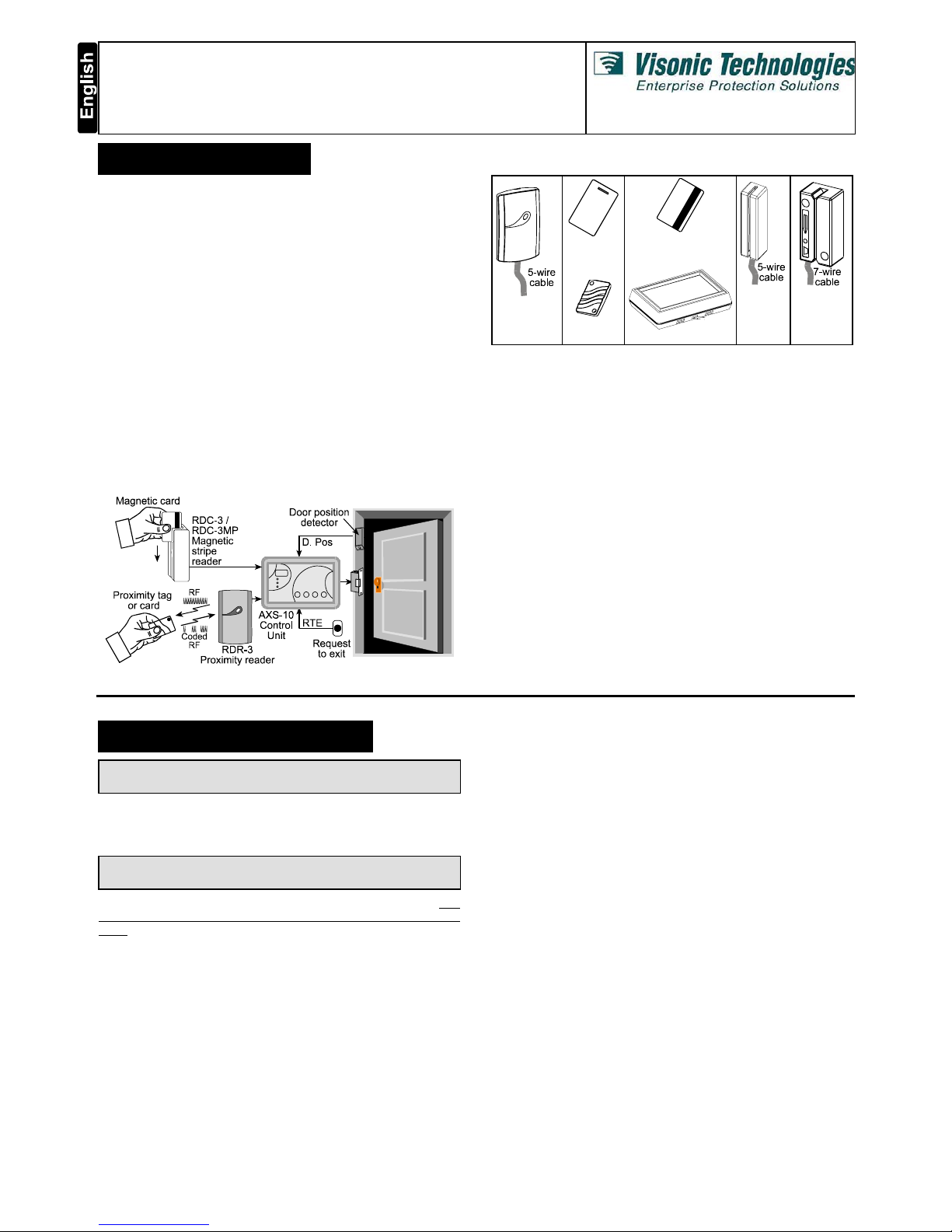
The Visonic Technologies AXS-10 is an electronic access control
system designed for a single access point, such as a main door
in an apartment building or individual office doors. The system
control unit relay activates a lock or electromagnetic strike lock
(EMS), when a valid proximity key (tag or card) is presented to
the reader located outside the protected area.
The use of a proximity (non-contact) key makes the installation of
the AXS-10 system an attractive possibility in harsh environments
and in places with poor lighting conditions. The proximity keys are
totally sealed and are wear resistant. The reader reads the key’s
ID, whenever the key is presented.
A second proximity reader may be connected to the AXS-10 to
control both sides of a door. An optional magnetic stripe card
reader may be connected instead of a proximity reader.
The separate weatherproof readers give added security and
flexibility allowing outdoor or indoor installation.
The AXS-10 control unit (see figure 1) includes a 3-digit display,
3 visual indicators (LEDs) and 4 buttons. An internal proximity
reader located in the upper right corner of the control panel
allows fast and easy programming of access keys. The buttons
are used for entering the password and for programming the unit.
Figure 1 - System Functional Presentation
RDR-3
Proximity
Reader
CRD-1
Prox. Card
TAG-1
Prox. Tag
CRD-1M Magnetic
Stripe Card
AXS-10 Control Unit
RDC-3
Magnetic
Stripe
Reader
RDC-3MP
Magnetic
Stripe
Reader
Figure 2 - System Components
A new Toggle mode feature is added to the AXS-10 controller. By
using this feature, presenting a valid tag arms/disarms an alarm
system or activate/deactivate an electrical device (such as air
conditioner).
The AXS-10 has a memory capacity of 300 keys. Adding keys
simply involves presenting new keys to the controller while the
system is in ADD mode.
The user can delete keys in the DELETE mode by presenting
them to the reader or, if a tag/card is not available, by typing in its
number (the same one that appears when adding the key).
The AXS-10 kit includes:
• AXS-10 controller
• RDR-3 proximity reader with 1m (3 ft) 5-wire cable
• Installation instructions
• User Guide
• Control unit base template, for wall installation
Additional tools and equipment that may be needed:
• Proximity tags or cards (ordered separately)
• Power supply for the controller - 12V AC/DC
• Electromagnetic strike (EMS) unit
• Request-to-exit push button or PIR, if “request to exit” option is
required.
2. USER PROGRAMMING
Note: While in any one of the programming modes, the AXS-10
will not operate the reader or the lock.
2.1 Entering the Programming Menu
The master key enables the user to select the programming
menu and add or delete keys.
Note: Inactivity for more than 10 seconds will cause AXS-10 to
exit the programming mode and revert to normal operation.
The AXS-10 recognizes one master key and one password. The
master key cannot be used as a user key and will NOT unlock the
door. To use the master key for entering the programming menu,
press the “MODE” button and then present the master key to the
internal reader, located at the top right corner or the AXS-10
controller, for 2 seconds. The reason for the 2 seconds delay is to
prevent inadvertent activation of the programming menu.
For setup functions such as “password”, “master key”, “unlock
time” or “erase all keys” an additional four-presses password is
needed. Each button press may involve pressing any one of the
four buttons or a combination of two.
Altogether, there are 10,000 password combinations (see “2.9
Setting Password”). The master key is also used to confirm
changes made to parameters.
2.2 Selecting The Programming Mode
The AXS-10 recognizes 6 programming modes:
• Adding User Keys
• Deleting User Keys
• Erasing All User Keys
• Setting Unlock Duration
• Defining Master Key
• Setting User Password
To select the programming mode, press the “MODE” button and
enter the installer password or present the master key to the
reader until the green led (“ADD” light) starts flashing for at least
2 seconds.
Press the “MODE” button to choose between Add, Delete and
Special Operations.
Adding User Keys is possible when the ADD light is ON.
Deleting User Keys is possible when the DELETE light is ON.
Set-up functions are available when the SPECIAL light is ON.
For set-up functions, enter the user’s password and select the
desired option by pressing the “MODE” button.
Page 2
2 DE6270U
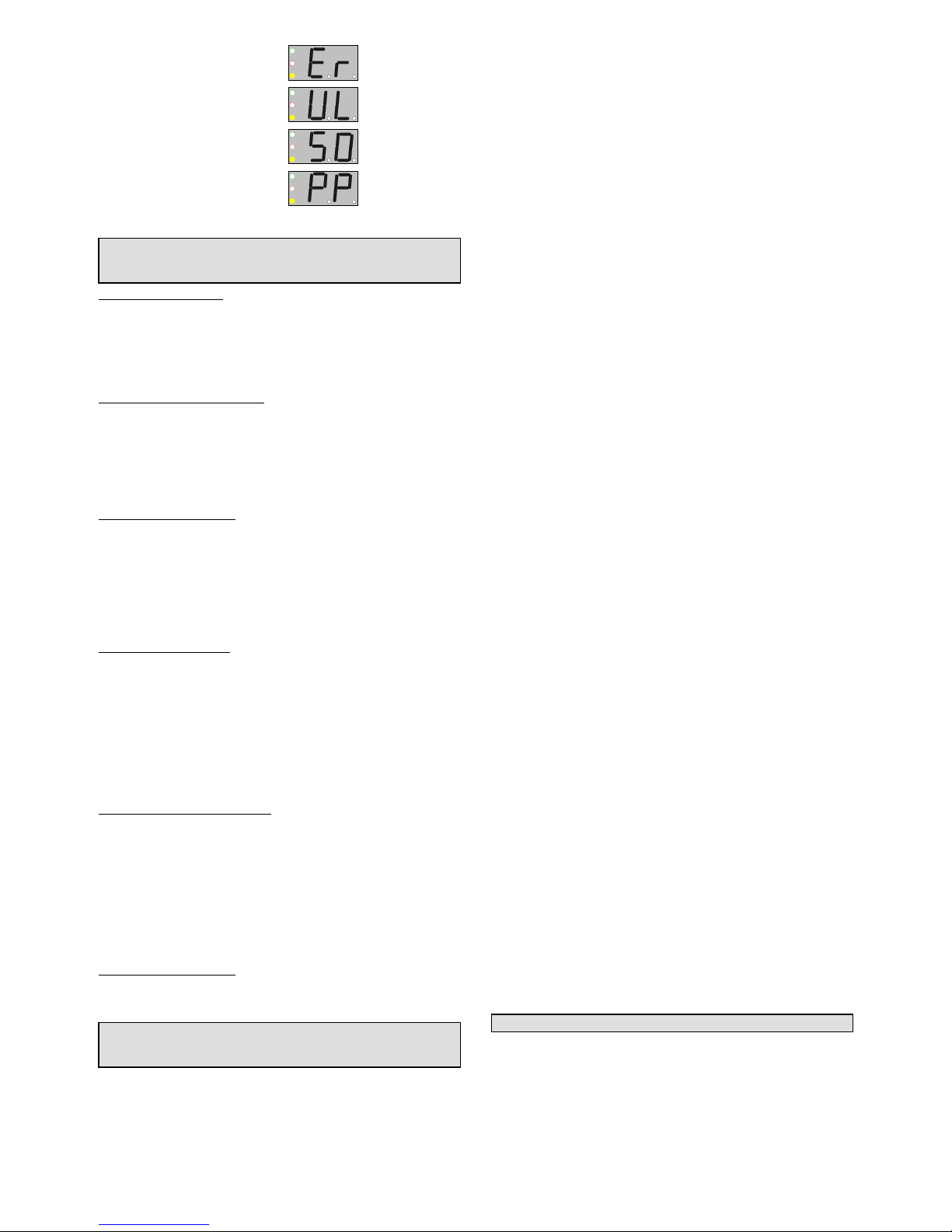
Erase All User Keys - “Er”
Set Unlock - “UL”
Set Master Key - “S0”
Set User Password - “PP”
2.3 Adding User Keys
Note: It is recommended to keep a list of key-holder names and
keys address numbers, in order to be able to delete stolen or
lost keys.
Adding Proximity Keys
• To select the ADD mode press the “MODE” button and enter the
installer password, or present the master key to the reader until
the green “ADD” LED starts flashing, indicating that the AXS-10
is ready to add a key.
• Once you present a key to the internal reader, the key will be
added and its number will be displayed for a few seconds.
Adding Magnetic Stripe Cards
• To select the ADD mode press the “MODE” button and present
the master card to the magnetic stripe reader until the green
“ADD” LED starts flashing, indicating that the AXS-10 is ready to
add a key.
• Once you present a magnetic stripe card to the magnetic stripe
reader, the card will be added and its number will be displayed
for a few seconds.
Final Steps of Procedure
• Write down the number and the card holder’s name for future
reference.
• After a few seconds the green LED will flash indicating that the
system is ready for adding the next key or magnetic stripe card.
• Add another key or magnetic stripe card or wait 5 seconds for the
system to time out and revert to normal operation.
2.4 Deleting User Keys
Deleting Proximity Keys
• To select the DELETE mode press the “MODE” button and
enter the installer password, or present the master key to the
reader until the “ADD” LED starts flashing, then press “MODE”
again. The red “DELETE” light will start flashing to indicate that
the system is ready to delete a key.
Deleting keys can be accomplished in two ways:
• If you have the key to be deleted, present it to the internal reader
located on the top right corner of the AXS-10 controller. The key
number will be displayed for a few seconds and then the numeric
display will blank to indicate readiness for the next operation.
Deleting Magnetic Stripe Cards
• To select the DELETE mode press the “MODE” button and
present the master card to the magnetic stripe reader until the
green “DELETE” LED starts flashing, indicating that the AXS-10
is ready to delete a key.
Deleting magnetic stripe cards can be accomplished in two ways:
• If you have the magnetic stripe card to be deleted, present it to
the magnetic stripe reader located on the top right corner of the
AXS-10 controller. The key number will be displayed for a few
seconds and then the numeric display will blank to indicate
readiness for the next operation.
Final Steps of Procedure
• To delete a missing key or magnetic stripe card, press the
“100”,“10” and “1” buttons until you reach the key or magnetic
stripe card number you wish to delete.
For example: To indicate the number 143, press the “100”
button once, then press the “10” button four times then press
the “1” button 3 times.
Once the number is set, present the master key or magnetic stripe
card, or press the “MODE” button to acknowledge the operation.
Hold the master key or magnetic stripe card until the key or
magnetic stripe card number disappears from the numeric display
and the red LED is ON. The red LED will start blinking again to
indicate that the system is ready for deleting the next key or
magnetic stripe card.
Present another key or magnetic stripe card to be deleted or wait 5
seconds for the system to time out and revert to normal operation.
2.5 Erasing ALL User Keys
• To select the ERASE ALL mode press the “MODE” button and
enter the installer password, or present the master key to the
reader until the ADD light starts blinking.
• For magnetic stripe cards, present the master card to the
magnetic stripe reader until the green LED starts flashing.
• Press “MODE” twice until the yellow “SPECIAL” LED lights (if
the master key is used, type the 4 level password and verify that
the display shows “Er”).
• To make sure that this function is not easily executed, you will
have to present the master key again until the yellow and green
LEDs light. This function does NOT erase the master key.
• Wait 5 seconds for the system to time out and revert to normal
operation.
2.6 Setting the Unlock Duration
The system default unlock duration is 5 seconds The time can be
set between 1 to 99 seconds.
Note: In Toggle mode, the unlock duration is unlimited (until a
valid tag is presented).
Setting Door Unlock Period:
• Press the “MODE” button.
• Enter the installer password or present the master key or
magnetic stripe card. The green “ADD” LED will start flashing
(if the master key is used, press the “MODE” button a few times
until the “SPECIAL” LED lights and the display shows “UL”).
• Press F2 (tens) and F3 (units) to set the unlock time in
seconds. For example, for 35 seconds press “10” three times
and “1” five times.
• The display will show the number of seconds.
• To save the unlock time and return to normal operation,
present the master key to the internal reader.
You may press “MODE” at any time to continue without saving
the new unlock duration.
2.7 Setting AXS-10 To Toggle Mode
To turn the AXS-10 into Toggle mode:
Setting the Unlock Duration (see par. 2.6) to 100 seconds turns
the AXS-10 into Toggle mode. If the unlock time setting is less
then 100 second, the AXS-10 is in regular mode.
To turn the AXS-10 from Toggle mode into Regular mode:
Set the unlock duration to any number other than "100", then exit
the unlock duration mode.
To turn the AXS-10 into Toggle mode by using master tag:
Note: If the system is reset, the system returns to idle mode.
• While the system is in idle mode present the master tag for 5
seconds to the RDR-3 reader.
The LED will change to green (the lock is unlocked and the
AXS-10 turns into Toggle mode).
• Presenting any valid non-master key will turn the relay to lock
position.
To turn the AXS-10 from Toggle mode to regular mode by
using the master key:
While the system is in idle mode, present the master tag for 5
seconds. The LED will blink red, which means that the AXS-10 is
in regular mode.
2.8 Setting The Master Key
Note: The AXS-10 can have only one master key.
• To change the master key, press the “MODE” button and enter
the installer password or present the master key or magnetic
stripe card to the reader until the “ADD” LED starts flashing.
Page 3

DE6270U 3
• Press “MODE” twice until the “SPECIAL” LED lights (if the
master key is used, type the 4 level password and verify that
the display shows “Er”, then Press “MODE” a few times until
the display shows “S0”).
• At this stage the system will try to read a key for up to ten
seconds.
• Hold the new master key until the green and yellow LED light.
• Wait 5 seconds for the system to time out and revert to normal
operation.
2.9 Setting the User Password
A password consists of four button presses, each involves either
pressing a single button or a combination of two buttons.
Note: The MODE key by itself cannot be used as the first
step of the password.
The following table shows the possible combinations:
MODE
+
F1
100
MODE
+
F3
1
F1
100
+
F2
10
MODE
F2
10
MODE
+
F2
10
F2
10
+
F3
1
F1
100
+
F3
1
F1
100
F3
1
A sample password:
F2
10
,
MODE
+
F1
100
,
F2
10
,
F2
10
+
F3
1
To select the CHANGE PASSWORD mode:
• Press the “MODE” button and enter the installer password, or
present the master key or magnetic stripe card to the reader
until the “ADD” LED starts blinking.
• Press the “MODE” button twice until the “SPECIAL” LED lights
(if the master key is used, enter the current 4 level password
and verify that the display shows “Er”, then press the “MODE”
button a few times until the display shows “PP”).
• Enter in the new password, as a combination of 4 button presses.
• Present the master key until the green and yellow LEDs light to
confirm acceptance of the password.
• Press “MODE” for the next programming modes or simply wait
5 seconds for the system to time out and revert to normal
operation.
3. NORMAL OPERATION
3.1 Valid Key Detection
If a key is presented to the external reader, the AXS-10 will
search the list of valid keys in its memory. If the key is found, the
AXS-10 will light the green LED and activate the output relay to
unlock the door for the pre-programmed unlock duration.
3.2 Invalid Key Detection
If the key presented to the reader is not found in the AXS-10
memory, the red LED will light for two seconds and the lock will
not open.
3.3 Key Event Log
By pressing F1 at idle mode, the AXS-10 shows up to 32 most
recent key numbers that unlocked the door. Returning to latest tag
can be accomplished by pressing F2 or F3.
3.4 Internal Request To Exit
The AXS-10 has a request-to-exit feature. To use it connect a
proper Normally Open switch or PIR detector to the Request-toexit terminal in the AXS-10. Each time the button is pressed or
the PIR detects, the relay output of the AXS-10 will be activated
for the pre-programmed unlock duration.
WARRANTY
Visonic Technologies Ltd. and/or its subsidiaries and its affiliates ("the Manufacturer")
warrants its products hereinafter referred to as "the Product" or "Products" to be in
conformance with its own plans and specifications and to be free of defects in materials and
workmanship under normal use and service for a period of twelve months from the date of
shipment by the Manufacturer. The Manufacturer's obligations shall be limited within the
warranty period, at its option, to repair or replace the product or any part thereof. The
Manufacturer shall not be responsible for dismantling and/or reinstallation charges. To
exercise the warranty the product must be returned to the Manufacturer freight prepaid and
insured.This warranty does not apply in the following cases: improper installation,
misuse, failure to follow installation and operating instructions, alteration, abuse, accident
or tampering, and repair by anyone other than the Manufacturer.
This warranty is exclusive and expressly in lieu of all other warranties, obligations or
liabilities, whether written, oral, express or implied, includ ing any warranty of
merchantability or fitness for a particular purpose, or otherwise. In no case shall the
Manufacturer be liable to anyone for any consequential or incidental damages for breach
of this warranty or any other warranties whatsoever, as aforesaid.
This warranty shall not be modified, varied or extended, and the Manufacturer does not
authorize any person to act on its behalf in the modification, variation or extension of this
warranty. This warranty shall apply to the Product only. All products, accessories or
attachments of others used in conjunction with the Product, including batteries, shall be
covered solely by their own warranty, if any. The Manufacturer shall not be liable for any
damage or loss whatsoever, whether directly, indirectly, incidentally, consequentially or
otherwise, caused by the malfunction of the Product due to products, accessories, or
attachments of others, including batteries, used in conjunction with the Products.
The Manufacturer does not represent that its Product may not be compromised and/or
circumvented, or that the Product will prevent any death, personal and/or bodily injury and/or
damage to property resulting from burglary, robbery, fire or otherwise, or that the Product will
in all cases provide adequate warning or protection. User understands that a properly installed
and maintained alarm may only reduce the risk of events such as burglary, robbery, and fire
without warning, but it is not insurance or a guarantee that such will not occur or that there will
be no death, personal damage and/or damage to property as a result.
The Manufacturer shall have no liability for any death, personal and/or bodily injury
and/or damage to property or other loss whether direct, indirect, incidental,
consequential or otherwise, based on a claim that the Product failed to function.
However, if the Manufacturer is held liable, whether directly or indirectly, for any loss or
damage arising under this limited warranty or otherwise, regardless of cause or origin, the
Manufacturer's maximum liability shall not in any case exceed the purchase price of the
Product, which shall be fixed as liquidated damages and not as a penalty, and shall be
the complete and exclusive remedy against the Manufacturer.
Warning: The user should follow the installation and operation instructions and among other
things test the Product and the whole system at least once a week. For various reasons,
including, but not limited to, changes in environmental conditions, electric or electronic
disruptions and tampering, the Product may not perform as expected. The user is advised to
take all necessary precautions for his /her safety and the protection of his/her property.
6/91
This device has been tested and found to comply with the limits for a Class B digital device, pursuant to Part 15 of the FCC Rules. These limits are
designed to provide reasonable protection against harmful interference in residential installations. This equipment generates, uses and can radiate
radio frequency energy and, if not installed and used in accordance with the instructions, may cause harmful interference to radio and television
reception. However, there is no guarantee that interference will not occur in a particular installation. If this device does cause such interference, which
can be verified by turning the device off and on, the user is encouraged to eliminate the interference by one or more of the following measures:
– Re-orient or re-locate the receiving antenna.
– Increase the distance between the device and the receiver.
– Connect the device to an outlet on a circuit different from the one which supplies power to the receiver.
– Consult the dealer or an experienced radio/TV technician.
VISONIC TECHNOLOGIES. (ISRAEL): 30 Habarzel St. Tel Aviv 69710 ISRAEL Tel 972-3-7681400 Fax: 972-3-7681415 E-MAIL: support@visonictech.com
VTA (VISONIC TECHNOLOGIES AMERICAS): 65 West Dudley Town Road, Bloomfield CT. 06002-1911 USA. TEL.: (860) 243 0833, (800) 223 0020 FAX: (860) 242-
8094. E-MAIL: usa_support@visonic.com
VT UK (VISONIC TECHNOLOGIES UK): Fraser Road, Priory Business Park, Bedford MK44 3WH ENGLAND. TEL.: 44-870-730-0840; FAX: 44-870-730-0839
INTERNET:
www.visonictech.com
VISONIC TECHNOLOGIES LTD. 2004 AXS-10 DE6270U (REV. 4, 10/2004)
Page 4

4 DE6270U
Appendix - Users List
Tag
No.
User name PIN
code
Tag
address
Tag
No.
User name PIN
code
Tag
address
1
001 51 051
2
002 52 052
3
003 53 053
4
004 54 054
5
005 55 055
6
006 56 056
7
007 57 057
8
008 58 058
9
009 59 059
10
010 60 060
11
011 61 061
12
012 62 062
13
013 63 063
14
014 64 064
15
015 65 065
16
016 66 066
17
017 67 067
18
018 68 068
19
019 69 069
20
020 70 070
21
021 71 071
22
022 72 072
23
023 73 073
24
024 74 074
25
025 75 075
26
026 76 076
27
027 77 077
28
028 78 078
29
029 79 079
30
030 80 080
31
031 81 081
32
032 82 082
33
033 83 083
34
034 84 084
35
035 85 085
36
036 86 086
37
037 87 087
38
038 88 088
39
039 89 089
40
040 90 090
41
041 91 091
42
042 92 092
43
043 93 093
44
044 94 094
45
045 95 095
46
046 96 096
47
047 97 097
48
048 98 098
49
049 99 099
50
050 100 100
Note
This is a sample user list for your convenience. Please copy the list as necessary.
 Loading...