

Instruction Manual
Barcode Reader VB34
FACTORY AUTOMATION

With regard to the supply of products, the current issue of the following document is applicable: The General
published by the Central Association of the Electrical Industry (Zentralverband Elektrotechnik und Elektroindus-
in its most recent version as well as the supplementary clause: "Expanded reservation of proprietorship"
For this reason, this printed matter is produced on paper bleached without the use of chlorine.
Terms of Delivery for Products and Services of the Electrical Industry,
trie (ZVEI) e.V.)
We at Pepperl+Fuchs/VISOLUX recognize a duty to make a contribution to the future.

Barcode reader VB34
S
P
Table of contents and general information
1 REFERENCE INFORMATION . . . . . . . . . . . . . . . . . . . . . . . . . . . . . . . . .4
1.1 ADDITIONAL DOCUMENTATION. . . . . . . . . . . . . . . . . . . . . . . . . . . . . . . . . . . . . 4
1.2 Maintenance, support and warranty . . . . . . . . . . . . . . . . . . . . . . . . . . . . . . . . . . 4
1.2.1 Maintenance and support. . . . . . . . . . . . . . . . . . . . . . . . . . . . . . . . . . . . . . . . . . . . 4
2 Safety regulations. . . . . . . . . . . . . . . . . . . . . . . . . . . . . . . . . . . . . . . . . .4
2.1 Electrical safety . . . . . . . . . . . . . . . . . . . . . . . . . . . . . . . . . . . . . . . . . . . . . . . . . . 4
2.2 Laser safety. . . . . . . . . . . . . . . . . . . . . . . . . . . . . . . . . . . . . . . . . . . . . . . . . . . . . . 4
2.2.1 Standard regulations. . . . . . . . . . . . . . . . . . . . . . . . . . . . . . . . . . . . . . . . . . . . . . . . 4
2.3 Voltage supply . . . . . . . . . . . . . . . . . . . . . . . . . . . . . . . . . . . . . . . . . . . . . . . . . . . 6
3 Device views . . . . . . . . . . . . . . . . . . . . . . . . . . . . . . . . . . . . . . . . . . . . . .6
4 Installation overview. . . . . . . . . . . . . . . . . . . . . . . . . . . . . . . . . . . . . . . .9
4.1 Point-to-point installation . . . . . . . . . . . . . . . . . . . . . . . . . . . . . . . . . . . . . . . . . . 9
4.2 Lonworks master/slave installation . . . . . . . . . . . . . . . . . . . . . . . . . . . . . . . . . . 9
5 Introduction. . . . . . . . . . . . . . . . . . . . . . . . . . . . . . . . . . . . . . . . . . . . . .11
5.1 Product description . . . . . . . . . . . . . . . . . . . . . . . . . . . . . . . . . . . . . . . . . . . . . . 11
5.2 Available models . . . . . . . . . . . . . . . . . . . . . . . . . . . . . . . . . . . . . . . . . . . . . . . . 13
5.3 Displays. . . . . . . . . . . . . . . . . . . . . . . . . . . . . . . . . . . . . . . . . . . . . . . . . . . . . . . . 13
5.4 Oscillating mirror models . . . . . . . . . . . . . . . . . . . . . . . . . . . . . . . . . . . . . . . . . 13
5.5 Accessories . . . . . . . . . . . . . . . . . . . . . . . . . . . . . . . . . . . . . . . . . . . . . . . . . . . . 16
6 Installation. . . . . . . . . . . . . . . . . . . . . . . . . . . . . . . . . . . . . . . . . . . . . . .16
6.1 Contents of the package . . . . . . . . . . . . . . . . . . . . . . . . . . . . . . . . . . . . . . . . . . 16
6.2 Mechanical installation . . . . . . . . . . . . . . . . . . . . . . . . . . . . . . . . . . . . . . . . . . . 17
6.2.1 Installation of the reader. . . . . . . . . . . . . . . . . . . . . . . . . . . . . . . . . . . . . . . . . . . . 17
6.2.2 Installation of the reader with accessories . . . . . . . . . . . . . . . . . . . . . . . . . . . . . . 20
6.3 Electrical connections . . . . . . . . . . . . . . . . . . . . . . . . . . . . . . . . . . . . . . . . . . . . 21
6.3.1 Primary/secondary interface and I/O connections . . . . . . . . . . . . . . . . . . . . . . . . 23
6.3.2 Lonworks connector . . . . . . . . . . . . . . . . . . . . . . . . . . . . . . . . . . . . . . . . . . . . . . . 32
6.3.3 Ethernet connector . . . . . . . . . . . . . . . . . . . . . . . . . . . . . . . . . . . . . . . . . . . . . . . . 35
6.3.4 DeviceNet connector . . . . . . . . . . . . . . . . . . . . . . . . . . . . . . . . . . . . . . . . . . . . . . 37
6.3.5 Profibus connector . . . . . . . . . . . . . . . . . . . . . . . . . . . . . . . . . . . . . . . . . . . . . . . . 37
6.3.6 Voltage supply . . . . . . . . . . . . . . . . . . . . . . . . . . . . . . . . . . . . . . . . . . . . . . . . . . . 38
6.4 Operator interface. . . . . . . . . . . . . . . . . . . . . . . . . . . . . . . . . . . . . . . . . . . . . . . . 39
6.5 Adjusting the reader. . . . . . . . . . . . . . . . . . . . . . . . . . . . . . . . . . . . . . . . . . . . . . 39
6.6 Typical installations . . . . . . . . . . . . . . . . . . . . . . . . . . . . . . . . . . . . . . . . . . . . . . 41
6.6.1 Standard installation. . . . . . . . . . . . . . . . . . . . . . . . . . . . . . . . . . . . . . . . . . . . . . . 41
6.6.2 Installation with an angle of rotation of 45°. . . . . . . . . . . . . . . . . . . . . . . . . . . . . . 41
6.7 Typical hardware configurations . . . . . . . . . . . . . . . . . . . . . . . . . . . . . . . . . . . 42
6.7.1 Point-to-point . . . . . . . . . . . . . . . . . . . . . . . . . . . . . . . . . . . . . . . . . . . . . . . . . . . . 42
6.7.2 Loops . . . . . . . . . . . . . . . . . . . . . . . . . . . . . . . . . . . . . . . . . . . . . . . . . . . . . . . . . . 43
6.7.3 RS232 master/slave . . . . . . . . . . . . . . . . . . . . . . . . . . . . . . . . . . . . . . . . . . . . . . . 45
6.7.4 Multiplexer . . . . . . . . . . . . . . . . . . . . . . . . . . . . . . . . . . . . . . . . . . . . . . . . . . . . . . 46
6.7.5 Local Lonworks network. . . . . . . . . . . . . . . . . . . . . . . . . . . . . . . . . . . . . . . . . . . . 47
6.7.6 Fieldbus network. . . . . . . . . . . . . . . . . . . . . . . . . . . . . . . . . . . . . . . . . . . . . . . . . . 50
6.8 FLASH™ dynamic focusing. . . . . . . . . . . . . . . . . . . . . . . . . . . . . . . . . . . . . . . . 51
6.8.1 Fixed adjustment . . . . . . . . . . . . . . . . . . . . . . . . . . . . . . . . . . . . . . . . . . . . . . . . . 52
Date of issue 06/13/2005
ubject to reasonable modifications due to technical advances. Copyright Pepperl+Fuchs, Printed in Germany
epperl+Fuchs Group • Tel.: Germany (06 21) 7 76-0 • USA (330) 4 25 35 55 • Singapore 7 79 90 91 • Internet http://www.pepperl-fuchs.com
1

Barcode reader VB34
S
P
Table of contents and general information
6.8.2 Continuous adjustment . . . . . . . . . . . . . . . . . . . . . . . . . . . . . . . . . . . . . . . . . . . . 52
6.8.3 Trigger operating mode . . . . . . . . . . . . . . . . . . . . . . . . . . . . . . . . . . . . . . . . . . . . 52
6.8.4 D-Flash™ operating mode. . . . . . . . . . . . . . . . . . . . . . . . . . . . . . . . . . . . . . . . . . 53
6.9 Key field and display . . . . . . . . . . . . . . . . . . . . . . . . . . . . . . . . . . . . . . . . . . . . . 53
6.9.1 Internal Net . . . . . . . . . . . . . . . . . . . . . . . . . . . . . . . . . . . . . . . . . . . . . . . . . . . . . 53
6.9.2 Test mode . . . . . . . . . . . . . . . . . . . . . . . . . . . . . . . . . . . . . . . . . . . . . . . . . . . . . . 54
7 Software configuration. . . . . . . . . . . . . . . . . . . . . . . . . . . . . . . . . . . . .54
7.1 Software installation . . . . . . . . . . . . . . . . . . . . . . . . . . . . . . . . . . . . . . . . . . . . . 54
7.2 Hints on quick configuration . . . . . . . . . . . . . . . . . . . . . . . . . . . . . . . . . . . . . . 55
7.2.1 Assistant for quickly setting up the reader . . . . . . . . . . . . . . . . . . . . . . . . . . . . . . 55
7.2.2 Network Assistant . . . . . . . . . . . . . . . . . . . . . . . . . . . . . . . . . . . . . . . . . . . . . . . . 58
7.3 Enhanced configuration . . . . . . . . . . . . . . . . . . . . . . . . . . . . . . . . . . . . . . . . . . 59
7.4 Basic settings for parameters . . . . . . . . . . . . . . . . . . . . . . . . . . . . . . . . . . . . . 60
8 Optical properties. . . . . . . . . . . . . . . . . . . . . . . . . . . . . . . . . . . . . . . . .63
8.1 ACR technology (ACR™ 3 reconstruction) . . . . . . . . . . . . . . . . . . . . . . . . . . . 63
8.1.1 Tilt angle for the ACR reconstruction. . . . . . . . . . . . . . . . . . . . . . . . . . . . . . . . . . 64
8.2 PackTrack™ . . . . . . . . . . . . . . . . . . . . . . . . . . . . . . . . . . . . . . . . . . . . . . . . . . . . 65
8.2.1 PackTrack™ calibration. . . . . . . . . . . . . . . . . . . . . . . . . . . . . . . . . . . . . . . . . . . . 66
8.3 Read diagrams . . . . . . . . . . . . . . . . . . . . . . . . . . . . . . . . . . . . . . . . . . . . . . . . . . 68
8.3.1 VB34 standard model . . . . . . . . . . . . . . . . . . . . . . . . . . . . . . . . . . . . . . . . . . . . . 69
8.3.2 VB34 model with reflex mirror . . . . . . . . . . . . . . . . . . . . . . . . . . . . . . . . . . . . . . . 79
9 Maintenance . . . . . . . . . . . . . . . . . . . . . . . . . . . . . . . . . . . . . . . . . . . . .89
9.1 Cleaning . . . . . . . . . . . . . . . . . . . . . . . . . . . . . . . . . . . . . . . . . . . . . . . . . . . . . . . 89
10 Troubleshooting . . . . . . . . . . . . . . . . . . . . . . . . . . . . . . . . . . . . . . . . . .89
11 Technical data. . . . . . . . . . . . . . . . . . . . . . . . . . . . . . . . . . . . . . . . . . . .93
12 Glossary . . . . . . . . . . . . . . . . . . . . . . . . . . . . . . . . . . . . . . . . . . . . . . . .95
13 Notes . . . . . . . . . . . . . . . . . . . . . . . . . . . . . . . . . . . . . . . . . . . . . . . . . . .99
General information
This symbol warns the user of possible danger. Failure to heed this
warning can lead to personal injury or death and/or damage to
equipment.
Warning
This symbol warns the user of the possibility of device failure. Failure to
observe this warning can lead to the complete failure of the device or
Attention
Note
ubject to reasonable modifications due to technical advances. Copyright Pepperl+Fuchs, Printed in Germany
2
epperl+Fuchs Group • Tel.: Germany (06 21) 7 76-0 • USA (330) 4 25 35 55 • Singapore 7 79 90 91 • Internet http://www.pepperl-fuchs.com
any device connected to it.
This symbol advises the user of important tips.
Date of issue 06/13/2005
Barcode reader VB34
S
P
Table of contents and general information
Declaration of conformity
We, Pepperl+Fuchs GmbH, declare herewith at our sole responsibility that the
Barcode Scanner VB34
and all models of this product to which this declaration pertains, are compliant with
the following standards and other regulating documents
EN 55022, August 1994: RADIO INTERFERENCE OF INFORMATION
TECHNOLOGY EQUIPMENT (ITE), MEASURING
METHODS AND LIMITS
EN 50082-2, March 1995: ELECTROMAGNETIC COMPATIBILITY,
GENERIC IMMUNITY STANDARD PART 2:
INDUSTRIAL AREA
and the guidelines of the following directive(s):
89/336 CEE AND SUBSEQUENT CHANGES MADE,
92/31 CEE; 93/68 CEE
A corresponding declaration of conformity may be requested from the
manufacturer.
Note
Pepperl+Fuchs GmbH, in D-68301 Mannheim, has a certified quality assurance
program in accordance with ISO 9001.
ISO9001
Date of issue 06/13/2005
ubject to reasonable modifications due to technical advances. Copyright Pepperl+Fuchs, Printed in Germany
epperl+Fuchs Group • Tel.: Germany (06 21) 7 76-0 • USA (330) 4 25 35 55 • Singapore 7 79 90 91 • Internet http://www.pepperl-fuchs.com
3

Barcode reader VB34
REFERENCE INFORMATION
1 REFERENCE INFORMATION
1.1 ADDITIONAL DOCUMENTATION
The following additional documentation on the VB34 system is available:
• C-BOX100 manual
• GFC-60 90° deflecting mirror
• GFC-600 90° near range deflecting mirror
• Documentation on Profibus communication
1.2 Maintenance, support and warranty
1.2.1 Maintenance and support
Pepperl+Fuchs offers a range of services as well as technical support via its website.
For further information, visit our website at www.pepperl-fuchs.com.
2 Safety regulations
2.1 Electrical safety
This product meets the applicable requirements stipulated by the European standard
EN 60950 on electrical safety in the version valid at the time of production.
2.2 Laser safety
The following information is listed for compliance with the rules defined by the
international authorities and refers to the proper use of the VB34 reader.
2.2.1 Standard regulations
This reader is provided with a low-energy laser diode. Even though, according to the
current state of knowledge, directly looking into the laser beam does not cause any
biological damage, you should avoid doing this as for all strong light sources such as
the sun.
Do not direct the laser beam, neither directly nor indirectly, e.g. via mirrors, into the
eyes of other people.
This product meets the applicable requirements of the European standard EN 608251 and the standard CDRH 21 CFR1040 in the version valid at the time of production.
The reader is classified as a class 2 laser product according to EN 60825-1 and as a
class II laser product according to the CDRH regulations.
Before opening the device for maintenance or installation purposes, switch off the
voltage supply in order to avoid exposure to dangerous laser radiation.
The device is equipped with a safety device, which only switches on the laser if the
motor has reached the minimum rotational speed for read mode.
Subject to reasonable modifications due to technical advances. Copyright Pepperl+Fuchs, Printed in Germany
4
Pepperl+Fuchs Group • Tel.: Germany +49 621 776-0 • USA +1 330 4253555 • Singapore +65 67799091 • Internet http://www.pepperl-fuchs.com
Date of issue 06/13/2005
Barcode reader VB34
Safety regulations
The use of different controls or settings as well as carrying out
operations other than those described here may cause exposure to
dangerous, visible laser radiation.
Warning
Laser radiation is visible to the human eye and is emitted through the window in the
head of the reader (Figure 3.1 and Figure 3.2).
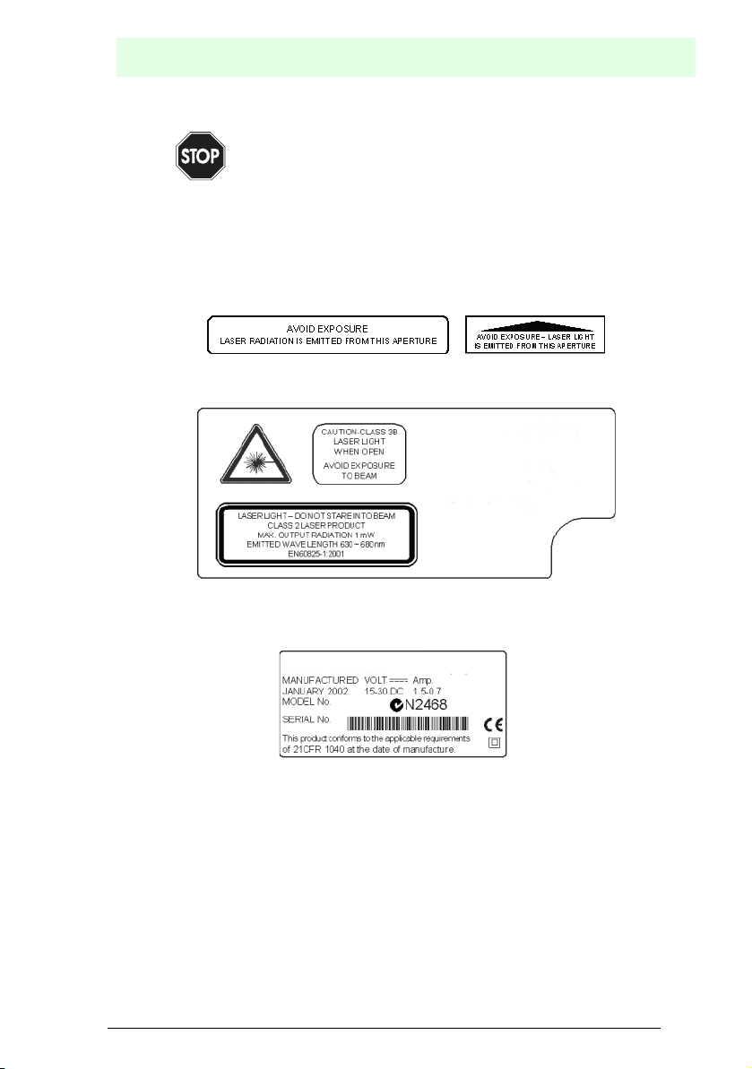
Warning labels that draw attention to the dangers of laser radiation and to the device
classification are located on the head of the reader (Figure 3.1 and Figure 3.2):
Figure 2.1 Laser safety labels for oscillating mirror and standard models
Figure 2.2 Warning and device classification labels
The name plate is located on the lower part of the reader (Figure 3.1):
Figure 2.3 Name plate
The laser diode used by this device is classified as a class 3B laser product according
to EN 60825-1 and as a class IIIb laser product according to the CDRH regulations.
As it is not possible to attach a label to the laser diode used by this device, the
following label is alternatively shown here:
Date of issue 06/13/2005
Subject to reasonable modifications due to technical advances. Copyright Pepperl+Fuchs, Printed in Germany
Pepperl+Fuchs Group • Tel.: Germany +49 621 776-0 • USA +1 330 4253555 • Singapore +65 67799091 • Internet http://www.pepperl-fuchs.com
5
Barcode reader VB34
Device views
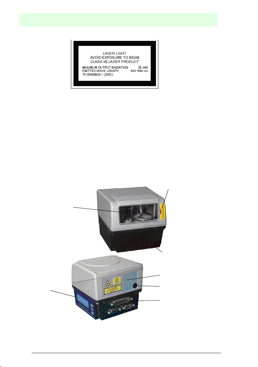
Figure 2.4 Classification label of the laser diode
Opening the optical components may cause radiation to be emitted with the maximum
power of the laser diode (35 mW at 630~680 nm).
2.3 Voltage supply
This product may be installed by qualified personnel only.
All VB34 models:
This device is designed for supply by a UL-listed power pack with the classification
“Class 2” or by a low-voltage power pack, which connects the supply voltage directly
via the 25/26-pin connector to the reader.
3 Device views
Laser safety label
Laser exit window
Name plate
Warning and device classification label
Display and
key pad
Figure 3.1 Device view VB34
Subject to reasonable modifications due to technical advances. Copyright Pepperl+Fuchs, Printed in Germany
6
Pepperl+Fuchs Group • Tel.: Germany +49 621 776-0 • USA +1 330 4253555 • Singapore +65 67799091 • Internet http://www.pepperl-fuchs.com
Service connection
Connector cover
Date of issue 06/13/2005
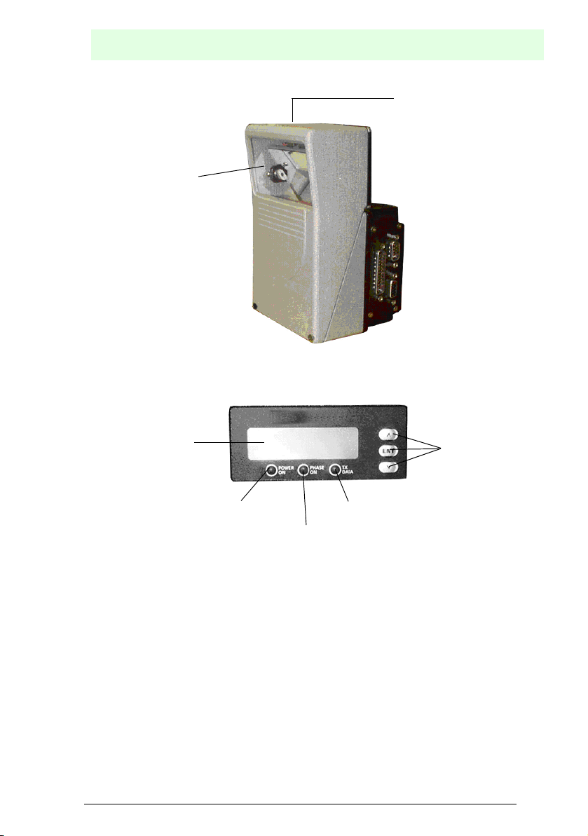
Laser exit window
Figure 3.2 Device view VB34 reflex mirror version
Barcode reader VB34
Device views
Laser safety label
LCD display
Power on LED
TXD data LED
Phase on LED
Program key pad
Figure 3.3 Partial view of display and key pad
Date of issue 06/13/2005
Subject to reasonable modifications due to technical advances. Copyright Pepperl+Fuchs, Printed in Germany
Pepperl+Fuchs Group • Tel.: Germany +49 621 776-0 • USA +1 330 4253555 • Singapore +65 67799091 • Internet http://www.pepperl-fuchs.com
7

Barcode reader VB34
Device views
25-pin Sub-D connector for primary/
secondary interface
9-pin Lonworks socket
Figure 3.4 View of connector cover for master/slave models
26-pin Sub-D connector for primary/
secondary interface
9-pin Lonworks socket
Figure 3.5 View of connector cover for Ethernet models
26-pin Sub-D connector for primary/
secondary interface
9-pin Lonworks connector
RJ45 connector for Ethernet
interface
5-pin DeviceNet connector
9-pin Lonworks socket
Figure 3.6 View of connector cover for DeviceNet models
26-pin Sub-D connector for primary/
secondary interface
9-pin Profibus socket
9-pin Lonworks socket
Figure 3.7 View of connector cover for Profibus models
Subject to reasonable modifications due to technical advances. Copyright Pepperl+Fuchs, Printed in Germany
8
Pepperl+Fuchs Group • Tel.: Germany +49 621 776-0 • USA +1 330 4253555 • Singapore +65 67799091 • Internet http://www.pepperl-fuchs.com
Date of issue 06/13/2005

Barcode reader VB34
Installation overview
4 Installation overview
4.1 Point-to-point installation
The following overview can also be used as a check list. It lists all the steps that are
required for a complete installation of the VB34 reader.
1. Read all the information in section "Safety instructions" at the beginning of this
manual.
2. Install the reader using the supplied mounting material (Chapter 6.2.2).
3. Adjust the reader to the correct reading distance for your model (Chapter 6.5).
4. Wire the VB34 reader according to the following steps:
a) Connect the VB34 reader to a C-BOX 100 (Chapter 5.5) using one of the
accessory cables.
b) Wire the C-BOX 100 with all system signals and voltages required by your
application (trigger, inputs, outputs).
• Layout: Point-to-point, RS232 master/slave, Lonworks or fieldbus. For further information, please refer to the sections in Chapter 6.7.
• Cabling: supply, primary serial interface – RS232, RS485 half duplex,
RS485 full duplex, 20 mA current loop, secondary interface, inputs, outputs
etc. For further information, please refer to the sections in Chapter 6.3.
5. Configure the VB34 reader by installing and executing the configuration software
from the enclosed CD-ROM. The most important steps are:
• Select the codes to be read
• Configure the communication parameters
• Define the data format parameters
• In the test mode, adjust your VB34 reader to the application as described
6. Complete the configuration program and start your application.
The installation is now complete.
in the configuration software.
4.2 Lonworks master/slave installation
The following overview can also be used as a check list. It lists all the steps that are
required for a complete installation of the VB34 reader.
1. Perform steps 1 to 3 of the point-to-point installation.
2. Wire the VB34 reader according to the following steps:
a) Connect the VB34 master reader to a C-BOX 100 (Chapter 5.5) using one of
the accessory cables.
b) Connect the BTK-6000 termination network to the VB34 master reader as
described under “Local Lonworks network” (Chapter 6.3.2).
c) Install and wire all slave readers required for your system configuration
(Chapter 6.7).
d) Connect the BTK-6000 termination network to the last VB34 slave reader as
described under “Local Lonworks network” (Chapter 6.3.2).
Date of issue 06/13/2005
Subject to reasonable modifications due to technical advances. Copyright Pepperl+Fuchs, Printed in Germany
Pepperl+Fuchs Group • Tel.: Germany +49 621 776-0 • USA +1 330 4253555 • Singapore +65 67799091 • Internet http://www.pepperl-fuchs.com
9

Barcode reader VB34
Installation overview
Configure the VB34 slave readers using one of the following methods:
a) Define the addresses of all VB34 slave readers via the key pad on the reader
(Chapter 6.9).
b) Configure all VB34 slave readers by installing and executing the configuration
software from the enclosed CD-ROM (Chapter 7.2.2).
Configure the VB34 master readers using one of the following methods:
c) Configure the VB34 reader as the master using the key pad of the reader
(Chapter 6.9).
d) Configure the VB34 reader as the master using configuration software
(Chapter 7.2.2).
3. Establish a connection to the VB34 master reader in order to configure the
network layout using the configuration software.
4. Configure all VB34 slave readers using the configuration software. The most
important steps are:
• Select the codes to be read
• Configure the communication parameters
• Define the data format parameters
All slave readers can also be configured externally using the
configuration software and the master reader.
Note
5. In the test mode, adjust your VB34 reader to the application as described in the
configuration software™.
The installation is now complete.
Subject to reasonable modifications due to technical advances. Copyright Pepperl+Fuchs, Printed in Germany
10
Pepperl+Fuchs Group • Tel.: Germany +49 621 776-0 • USA +1 330 4253555 • Singapore +65 67799091 • Internet http://www.pepperl-fuchs.com
Date of issue 06/13/2005

5 Introduction
5.1 Product description
The VB34 is the high-performance laser scanner in the VISOLUX family of barcode
readers for industrial applications. With its completely new hardware and software
platform, it offers innovative and modular solutions regarding performance,
communication and maintenance.
Easy installation and operation as well as high flexibility were the most important
features during the development of the VB34. Together with the Step-a-Head™
technology, for which a patent has been applied, the innovative mechanics makes it
possible to turn the read head and the decoder base assembly independently of each
other. Step-a-Head™ makes it possible to always install the VB34 in the ideal position
by changing the position of the base assembly while the read head with the laser
maintains its optimum position. This minimises the space requirements and simplifies
the installation.
Another innovation of the VB34 is the linear motor, which can be used to control the
reading position of the scanner via software. This dynamic system with the name
Flash™ is able to assume any reading position from the minimum position to the
maximum position in less than 10 ms. In typical applications with a reading distance
of less than 1 m, the reading position is reached in 4 ms.
Thanks to a new generation of decoders with StrongARM CPU and ACR technology
(ACR™ 3 reconstruction), the VB34 reads all current barcodes, even under
demanding ambient conditions.
The reader is also available in a version with an integrated, software-programmable
oscillating mirror.
Another focus in the system design was the communication capacity of the readers.
As interfaces, Lonworks, Profibus, DeviceNet and Ethernet were each integrated into
a separate version of the decoder base assembly.
Some of the significant features of the VB34 are:
• Read rate of up to 1200 read processes/second
• 2 serial interfaces
• Reading all current codes
• Operating voltage of 15 to 30 V DC
• All electrical connections pluggable
• Fast Lonworks interface for master/slave configurations
• Supports Profibus, DeviceNet and Ethernet
• 5 operating modes for an optimum adjustment to different application requirements
• Light source: laser diode with a wave length of 630 to 680 nm
• IP64-protected housing (for Ethernet models not yet available)
Auto-ID applications are traditionally used in the area of production. With increasing
marketability, standard solutions and a dynamic competition develop. The VB3x
family with the model VB33 also has its roots in production applications. The VB34
opens up new areas of application such as, for example, transport and logistics
applications, in which the practical advantages of the new technologies come to the
Date of issue 06/13/2005
fore.
Barcode reader VB34
Introduction
Subject to reasonable modifications due to technical advances. Copyright Pepperl+Fuchs, Printed in Germany
Pepperl+Fuchs Group • Tel.: Germany +49 621 776-0 • USA +1 330 4253555 • Singapore +65 67799091 • Internet http://www.pepperl-fuchs.com
11

Barcode reader VB34
Introduction
Feature Practical use
Modular solution with separate head
and base assembly as well as StepA-Head™ function
Reading pallets or large objects over
greater distances and with a large
field of view
Reading objects on conveyor belts • VB34 implements Packtrack™ function-
Master is used as multiplexer in fast
Lonworks environments
Configuration software • Short learning time thanks to integrated
• Combination of the ideal head and base
assemblies for a given application
• Scaleable solution
• Reduced tool life, as the decoder base
remains functional even when the head
has been removed.
• Simple maintenance: All configuration
parameters remain saved in the base
assembly. When the read head is
replaced, the scanner is configured automatically.
• Simple installation with minimum space
requirement
• VB34 with dynamic focussing system
Flash™.
ality in order to increase the production
of the plant by a higher system throughput.
• Economically, a very attractive offer as
there are no costs for the external multiplexer.
• High data throughput of 1.2 Mbit/s on a
sturdy, industry-proof bus.
wizard
• Multi-language platform
• All configuration parameters are saved in
the reader.
• Independent of the installed hardware
interface
Subject to reasonable modifications due to technical advances. Copyright Pepperl+Fuchs, Printed in Germany
12
Pepperl+Fuchs Group • Tel.: Germany +49 621 776-0 • USA +1 330 4253555 • Singapore +65 67799091 • Internet http://www.pepperl-fuchs.com
Date of issue 06/13/2005
Barcode reader VB34
Introduction
5.2 Available models
The VB34 scanner is available in various versions, which differ in the following
features:
• Optical system (head)
• Decoder (base assembly)
The following models are available:
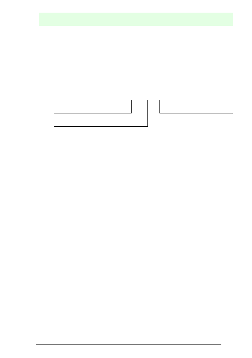
VB34 - xxxx - OM - y
Max. distance Decoder model (base assembly)
__ = master/slave
Optical model (head) P = Profibus
_ = Standard B12 = Ethernet
OM = Oscillating mirror B7 = DeviceNet
5.3 Displays
The VB34 decoder base assembly has an LCD display for system messages and
menus of the configuration software. The three keys on the side of the display are
used for navigating in the menus of the configuration software (Figure 3.3).
The three status LEDs have the following functions:
Power ON (Red) indicates that the reader is switched on (Figure 3.3)
Phase ON (Yellow)indicates that the presence sensor is activated (Figure 3.3).
TX Data (Green)indicates that the primary serial interface transmits data
without errors (Figure 3.3).
5.4 Oscillating mirror models
Oscillating mirror models are used when large reading areas must be covered, mainly
in the case of horizontal barcodes (picket fence barcodes).
The VB34 contains a special optical head with an integrated oscillating mirror, which
is driven by a linear motor. Speed, precision, repeatability and reliability of this drive
technology guarantee a high performance.
The new oscillating mirror is completely software-controlled and programmable. The
configuration™ software makes it possible to adjust the speed of the linear motor (and
thus the oscillation frequency) as well as the upper and lower end position for the
oscillation process as an angle.
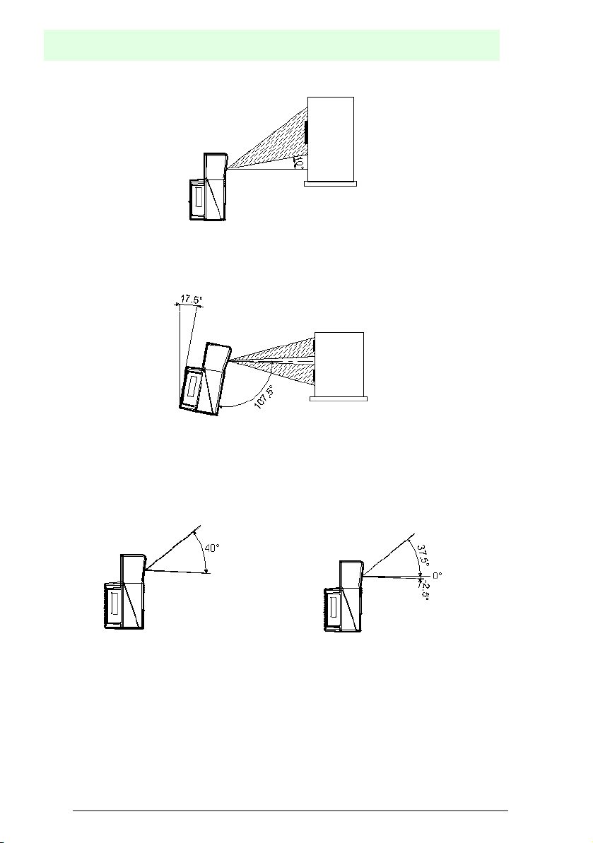
If the oscillating mirror is programmed to read barcodes at a very small angle, position
the reader in such a way that the visual angle is at least 10° (Chapter 6.4). This angle
mirrors the smallest deflection or the scanning line that is closest to the horizontal. All
other scanning lines have a visual angle of more than 10°. This prevents a direct
reflection of the laser beam emitted by the reader.
Date of issue 06/13/2005
Subject to reasonable modifications due to technical advances. Copyright Pepperl+Fuchs, Printed in Germany
Pepperl+Fuchs Group • Tel.: Germany +49 621 776-0 • USA +1 330 4253555 • Singapore +65 67799091 • Internet http://www.pepperl-fuchs.com
13
Barcode reader VB34
Introduction
Figure 5.1 Visual angle for oscillating mirror models
Otherwise, the scanner can be installed with a tilt angle of 17.5° in order to achieve a
horizontally symmetric deflection range.
Figure 5.2 Reading position of the oscillating mirror
In the above example, the zone in which the scanning lines meet the reflecting surface
vertically corresponds to a neutral area in the middle of the reading field.
The mirror can be deflected by up to 40°. In relation to the central axle of the exit
window, the deflection angle is asymmetric.
Figure 5.3 Maximum deflection and asymmetry of the oscillating mirror
Subject to reasonable modifications due to technical advances. Copyright Pepperl+Fuchs, Printed in Germany
14
Pepperl+Fuchs Group • Tel.: Germany +49 621 776-0 • USA +1 330 4253555 • Singapore +65 67799091 • Internet http://www.pepperl-fuchs.com
Date of issue 06/13/2005
Barcode reader VB34
Introduction
By configuring the oscillating mirror speed to 19 Hz, a raster for recording and reading
quickly moving objects can be reproduced.
Hz Max. deflection
0 ... 5 40°
6 ... 10 30°
11 ... 15 20°
16 ... 19 10°
The number of scans on a given reading area can be increased by
limiting the raster width to the required minimum.
Note
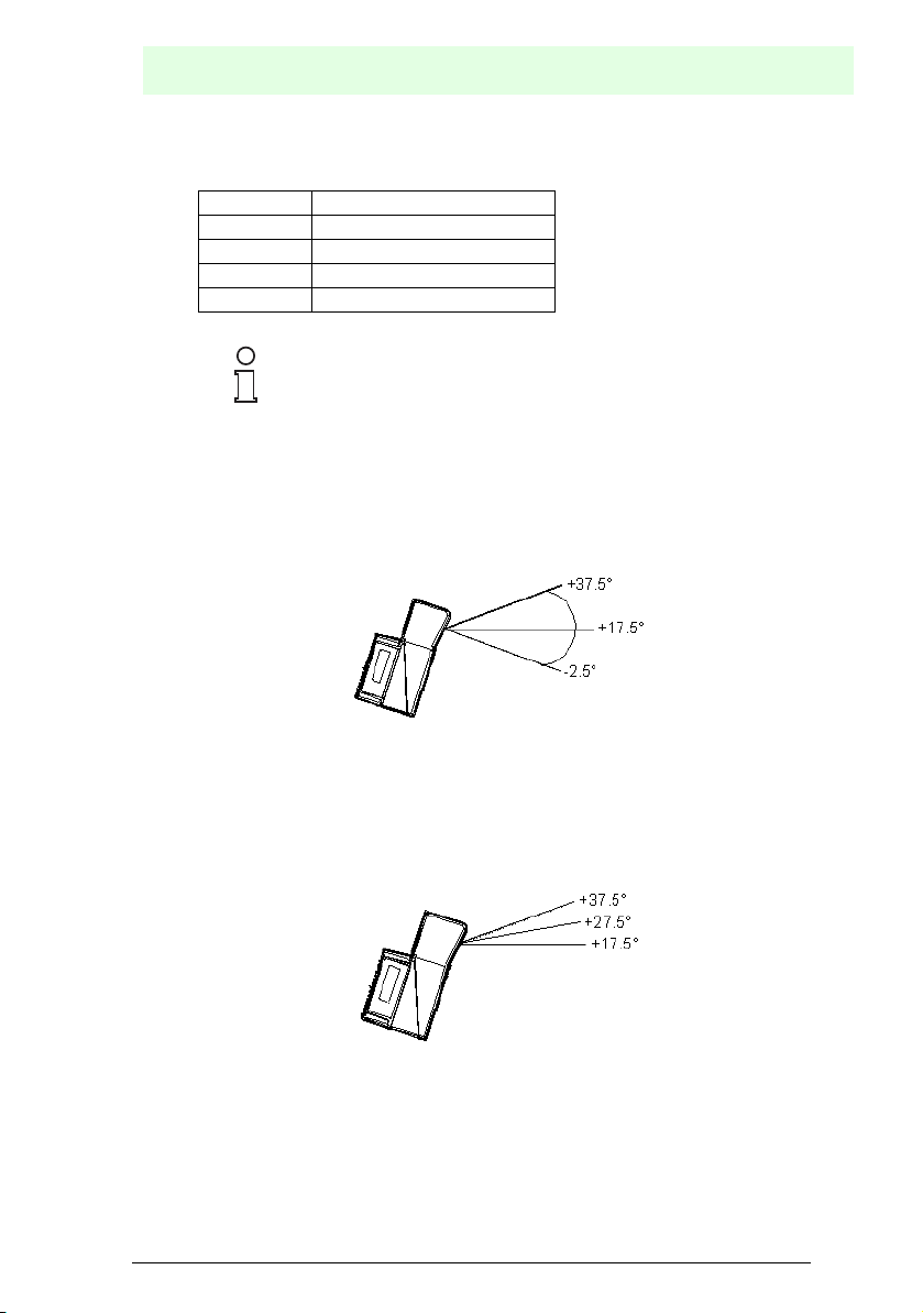
The oscillating angles are selected in the software. The minimum and maximum
values are –2.5° and +37.5° respectively.
The scanner can be tilted so that the software setting of 17.5° lies on the horizontal
as a 0° reference.
Figure 5.4 End angle position for the oscillating mirror
These models have a higher read rate (1200 read processes/second) than the
standard models, which is not influenced by the oscillating mirror.
The following example shows a setting of +10° for the lower line and an angle of +20°
for the upper line (see figure below).
Figure 5.5 Oscillating mirror operation
For details on mounting oscillating mirror model, please refer to Chapter 6.2.1.
Date of issue 06/13/2005
Subject to reasonable modifications due to technical advances. Copyright Pepperl+Fuchs, Printed in Germany
Pepperl+Fuchs Group • Tel.: Germany +49 621 776-0 • USA +1 330 4253555 • Singapore +65 67799091 • Internet http://www.pepperl-fuchs.com
15

Barcode reader VB34
Installation
5.5 Accessories
For the VB34, the following accessories can be ordered:
Accessories Description
CAB-6002 SH3339 Cable on C-BOX 100, 2 m length
CAB-6005 SH3339 Cable on C-BOX 100, 5 m length
CAB-6012 SH3339 Cable on C-BOX 100, 2 m length (VB34 fieldbus version)
CAB-6015 SH3339 Cable on C-BOX 100, 5 m length (VB34 fieldbus version)
CAB-6102 Master/slave cable, 2 m length
CAB-6105 Master/slave cable, 5 m length
CAB-6112 Master/slave cable, without supply, 2 m
CAB-6115 Master/slave cable, without supply, 5 m
INT-60 20 mA interface card
GFC-600 90° near range deflecting mirror
C-BOX 100 Passive connection box
C-BOX 300 Profibus DP connection box
BTK-6000 Termination networks set (5 units)
FBK-6000 Quick mounting bracket (2 parts)
GFC-60 90° deflecting mirror
US-60 Mounting angle set (5 units) for multiple-side stations
6 Installation
To install the system, proceed as follows
• Select the installation location for the VB34.
• Install the VB34 reader.
• Establish all electrical connections to the system.
• Direct the reader to the barcodes.
• Install the configuration software on the PC.
• Configure the dynamic Flash™ focussing using the configuration software.
If in your system the VB34 reader is connected to a C-BOX100,
please refer to the details in section "Additional documentation".
Note
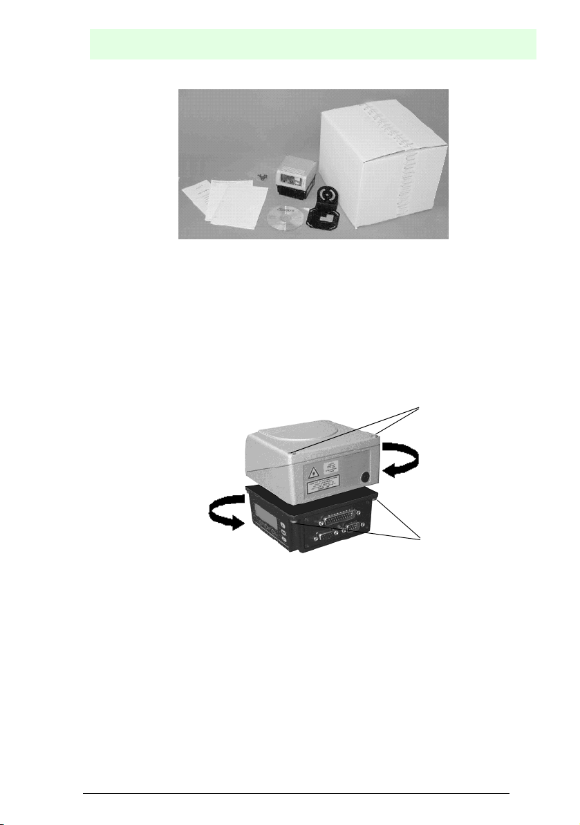
6.1 Contents of the package
When opening the packaging, make sure that the VB34 reader is undamaged and
that all parts of the following packing list are contained in the packaging. This packing
list contains:
• VB34 reader
• Instruction manual
• CD-ROM with the configuration software
• Mounting angle and screws
Subject to reasonable modifications due to technical advances. Copyright Pepperl+Fuchs, Printed in Germany
16
Pepperl+Fuchs Group • Tel.: Germany +49 621 776-0 • USA +1 330 4253555 • Singapore +65 67799091 • Internet http://www.pepperl-fuchs.com
Date of issue 06/13/2005
Barcode reader VB34
Figure 6.1 VB34 - contents of the package
6.2 Mechanical installation
6.2.1 Installation of the reader
Thanks to Step-a-Head™, the VB34 reader can be adjusted and installed in the ideal
reading position. By separating the head and the base assembly, you can change the
adjustment of the decoder base assembly and thus of the display, key pad and
connectors, while the head with the optical reading system maintains its optimum
position. The head and the base assembly can be turned independently of each other,
thus making a successful installation possible even in critical environments .
Head screws
Installation
Fixing screws
Figure 6.2 Step-a-Head™ function
To turn the head of the reader, perform the following steps:
1. Remove the head from the base by the unscrewing the four fixing screws.
2. Turn the head into the desired position.
3. Unscrew the two screws on the head.
4. Fix the head on the base assembly by tightening the four fixing screws again.
5. Tighten the two screws on the head.
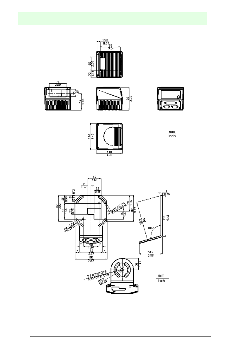
The following figures show the total dimensions of the standard model, the oscillating
mirror model and the mounting angles for installation. For a description of the
alignment of the reader in relation to the read zone, please refer to Chapter 6.5.
Date of issue 06/13/2005
Subject to reasonable modifications due to technical advances. Copyright Pepperl+Fuchs, Printed in Germany
Pepperl+Fuchs Group • Tel.: Germany +49 621 776-0 • USA +1 330 4253555 • Singapore +65 67799091 • Internet http://www.pepperl-fuchs.com
17
Barcode reader VB34
Installation
Figure 6.3 Dimensions VB34
Figure 6.4 Dimensions of mounting angle ST-237
Subject to reasonable modifications due to technical advances. Copyright Pepperl+Fuchs, Printed in Germany
18
Pepperl+Fuchs Group • Tel.: Germany +49 621 776-0 • USA +1 330 4253555 • Singapore +65 67799091 • Internet http://www.pepperl-fuchs.com
Date of issue 06/13/2005
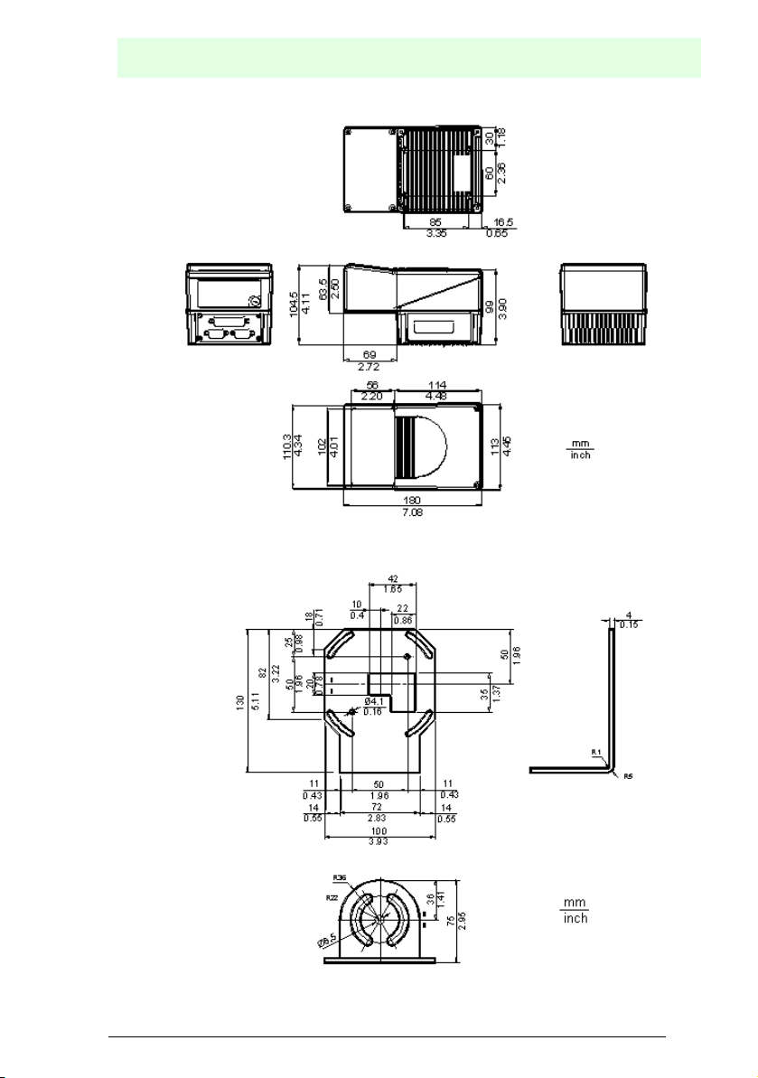
Figure 6.5 Dimensions of VB34 oscillating mirror model
Barcode reader VB34
Installation
Date of issue 06/13/2005
Subject to reasonable modifications due to technical advances. Copyright Pepperl+Fuchs, Printed in Germany
Pepperl+Fuchs Group • Tel.: Germany +49 621 776-0 • USA +1 330 4253555 • Singapore +65 67799091 • Internet http://www.pepperl-fuchs.com
Figure 6.6 Dimensions of mounting angle ST-210
19
Barcode reader VB34
Installation
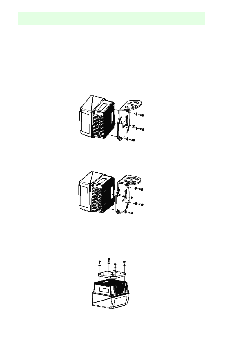
6.2.2 Installation of the reader with accessories
The following accessories make it possible to install the VB34 reader in the ideal
position for network layout:
• ST-237 mounting angle
• ST-210 mounting angle
• FBK-6000 quick mounting bracket
ST-237 is a mounting angle with 105° for mounting the reader as shown in the
following figure:
Figure 6.7 Fixing the ST-237 mounting angle
ST-210 is a mounting angle with 90° for mounting the reader as shown in the following
figure:
Figure 6.8 Fixing the ST-210 mounting angle
FBK-6000 is a quick mounting bracket set for easily and quickly mounting the reader
in ST-210 or ST-237 mounting angles.
First, the FBK-6000 mounting bracket must be fixed to the VB34 reader by means of
the screws:
Figure 6.9 Fixing the FBK-6000 mounting bracket to the reader
Subject to reasonable modifications due to technical advances. Copyright Pepperl+Fuchs, Printed in Germany
20
Pepperl+Fuchs Group • Tel.: Germany +49 621 776-0 • USA +1 330 4253555 • Singapore +65 67799091 • Internet http://www.pepperl-fuchs.com
Date of issue 06/13/2005
Barcode reader VB34
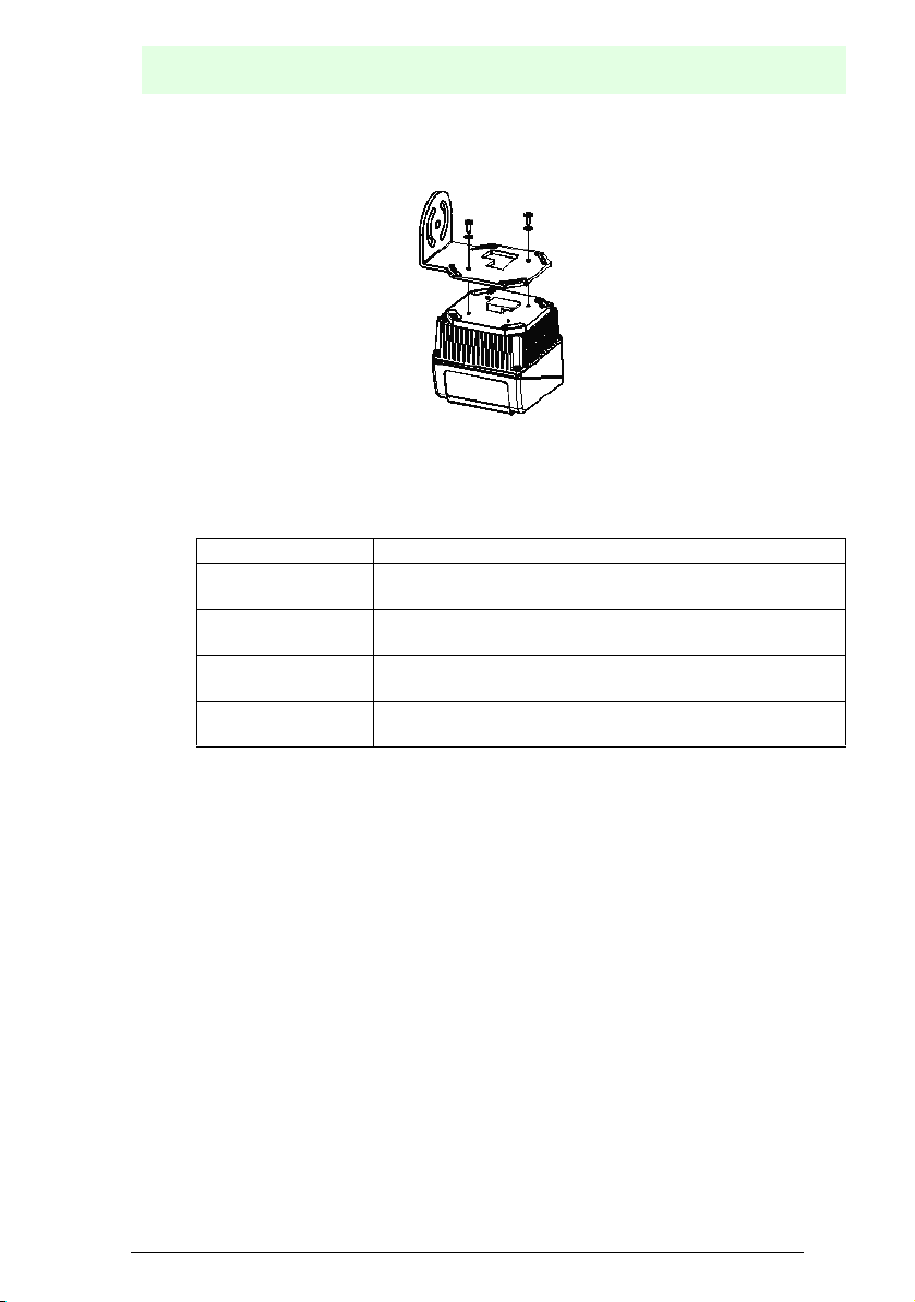
Afterwards, fix the assembly to the mounting angle by hanging the hook into the
recess of the mounting angle. Fix the assembly by means of 2 screws:
Figure 6.10 Fixing the assembly to the mounting angle
6.3 Electrical connections
The individual reader models have the following connectors:
Reader model Connector
Master/slave 25-pin connector for interface and input/output connections
9-pin connector, Lonworks 9-pin socket, Lonworks
EtherNet 26-pin connector for interface and input/output connections
9-pin socket, Lonworks RJ45 connector
DeviceNet 26-pin connector for interface and input/output connections
9-pin socket, Lonworks 5-pin connector
Profibus 26-pin connector for interface and input/output connections
9-pin socket, Lonworks 9-pin socket, Profibus
Installation
Date of issue 06/13/2005
Subject to reasonable modifications due to technical advances. Copyright Pepperl+Fuchs, Printed in Germany
Pepperl+Fuchs Group • Tel.: Germany +49 621 776-0 • USA +1 330 4253555 • Singapore +65 67799091 • Internet http://www.pepperl-fuchs.com
21
Barcode reader VB34
Installation
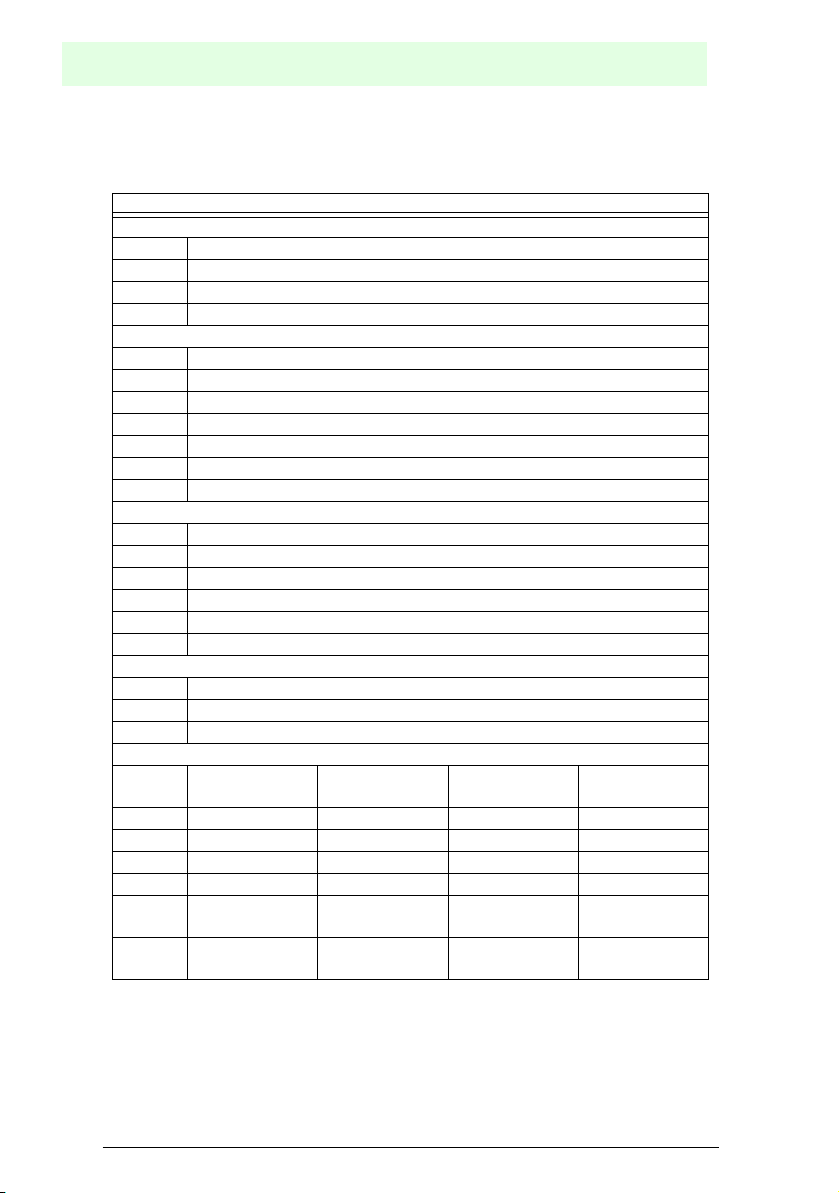
The following table shows the assignment of the connectors on the terminal block of
the C-BOX 100. Use this connection layout if the VB34 reader is connected to a network via the C-BOX 100:
Connectors on the terminal block of the C-BOX 100
Power supply
1, 3, 5 VS
2, 4, 6 GND
7, 8 Grounding
20, 40 Reserved
Inputs
27 EXT TRIG A (polarity exchangeable)
28 EXT TRIG B (polarity exchangeable)
29 IN 2A (polarity exchangeable)
30 IN 2B (polarity exchangeable)
31, 33 IN 3A (polarity exchangeable)
32, 34 IN 4A (polarity exchangeable)
36 IN 3B/IN 4B reference earth (polarity exchangeable)
Outputs
21 Out 1+
22 Out 123 Out 2+
24 Out 225 Out 3A (polarity exchangeable)
26 Out 3B (polarity exchangeable)
Secondary interface
35 TX AUX
37 RX AUX
38, 39 GND
Primary interface
RS232 RS485
full duplex
11, 15 TX232 TX485+ RTX485+ CLOUT+
12, 16 RTS232 TX485- RTX485- CLOUT-
17 RX232 RX485+ CLIN+
18 CTS232 RX485- CLIN-
10, 14,
19
SGND
Signal ground
SGND
Signal ground
9, 13 RS485
Shielding
RS485
half duplex
SGND
Signal ground
RS485
Shielding
(only INT-60)
20 mA
Subject to reasonable modifications due to technical advances. Copyright Pepperl+Fuchs, Printed in Germany
22
Pepperl+Fuchs Group • Tel.: Germany +49 621 776-0 • USA +1 330 4253555 • Singapore +65 67799091 • Internet http://www.pepperl-fuchs.com
Date of issue 06/13/2005
Barcode reader VB34
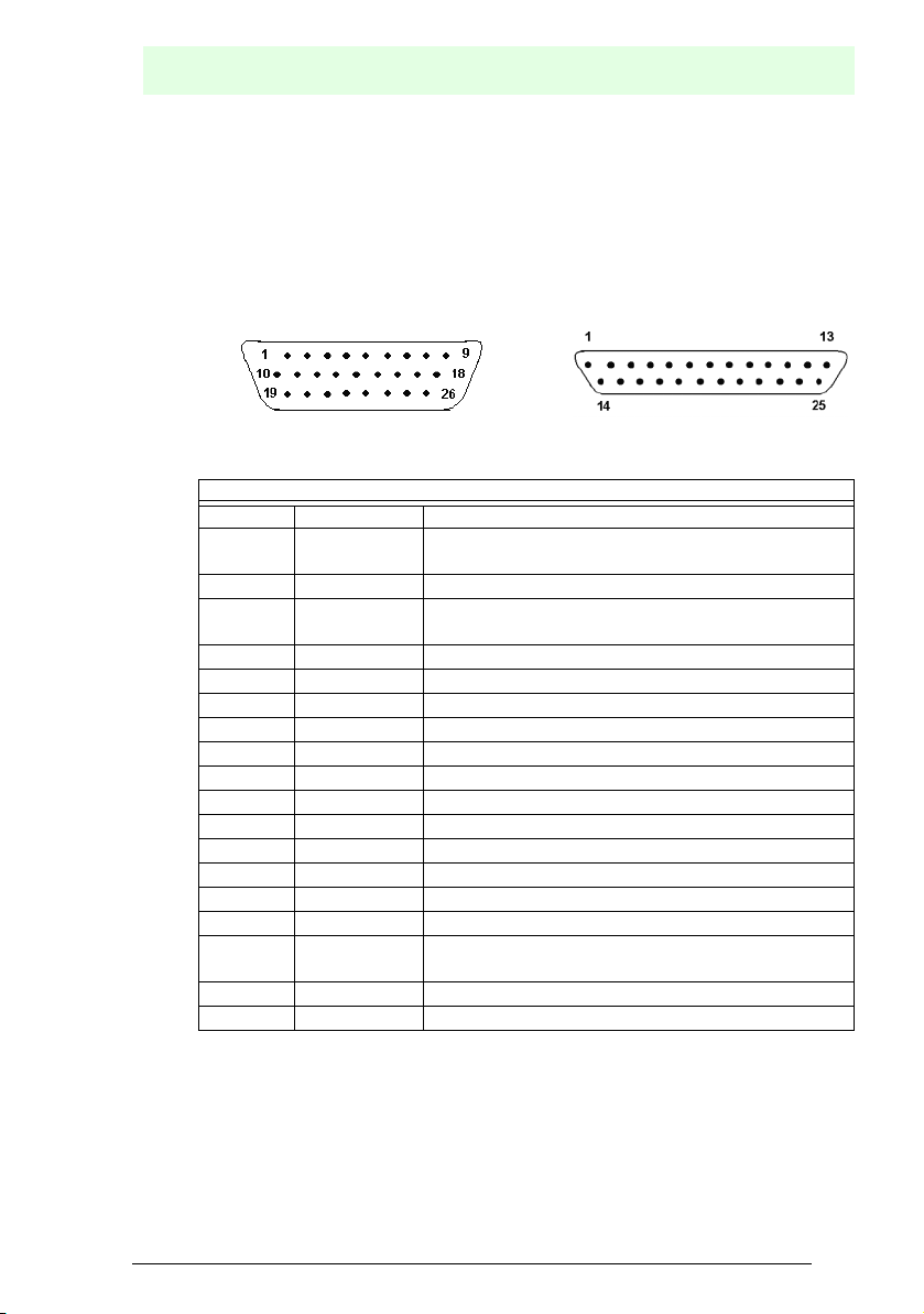
6.3.1 Primary/secondary interface and I/O connections
The VB34 reader has a 25-pin Sub-D connector for connection to computer, voltage
supply and input/output signals.
The fieldbus models (Ethernet, DeviceNet and Profibus) of the VB34 are equipped
with a 26-pin connector instead of the 25-pin connector.
The connection layout of this connector is shown in the following table:
Figure 6.11 26-pin connector 25-pin connector
VB34 connection layout of the 25/26-pin Sub-D connector
Pin Description Function
1 Shield The shielding is internally connected with chassis
ground via a capacitor.
20 RXAUX Received data of the RS232 interface (ground-related)
21 TXAUX Transmitted data of the RS232 interface (ground-
related)
8 Out 1+ Plus lead of the digital output 1
22 Out 1- Minus lead of the digital output 1
11 Out 2+ Plus lead of the digital output 2
12 Out 2- Minus lead of the digital output 2
16 Out 3A Digital output 3 - polarity exchangeable
17 Out 3B Digital output 3 - polarity exchangeable
18 EXT_TRIG A External trigger (polarity exchangeable)
19 EXT_TRIG B External trigger (polarity exchangeable)
6 IN 2A Input signal 2 (polarity exchangeable)
10 IN 2B Input signal 2 (polarity exchangeable)
14 IN 3A Input signal 3 (polarity exchangeable)
15 IN 4A Input signal 4 (polarity exchangeable)
24 IN_REF Common reference earth for IN3 and IN4 (polarity
exchangeable)
9, 13 VS Supply voltage - plus
23, 25, 26* GND Supply voltage - minus (ground)
* Pin 26 is only present on fieldbus models (Ethernet, DeviceNet or Profibus).
Installation
Date of issue 06/13/2005
Subject to reasonable modifications due to technical advances. Copyright Pepperl+Fuchs, Printed in Germany
Pepperl+Fuchs Group • Tel.: Germany +49 621 776-0 • USA +1 330 4253555 • Singapore +65 67799091 • Internet http://www.pepperl-fuchs.com
23
Barcode reader VB34
Installation
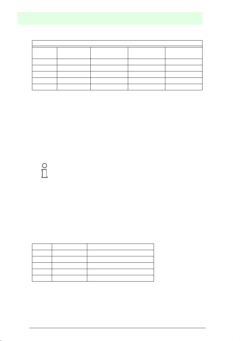
Connection layout of the connector for the primary interface
Pin RS232 RS485
full duplex
2 TX TX485+ RTX485+ CLOUT+
3 RX RX485+ CLIN+
4 RTS TX485- RTX485- CLOUT5 CTS RX485- CLIN7 GND_ISO GND_ISO GND_ISO GND**
** For 20 mA current loop, GND lies on the ground potential of the
reader voltage supply.
Primary interface
The primary serial interface supports the following interface standards:
• RS232
• RS485 full duplex
• RS485 half duplex
• 20 mA current loop
The 20 mA interface is only available if the INT-60 accessory option is installed. This
accessory interface replaces the RS232/RS485 interface.
Interface type and transmission parameters (baud rate, data bits etc.)
are configured using the configuration software. For further
information, please refer to section "Main Serial Port" in the online
Note
help.
RS485
half duplex
(only INT-60)
20 mA
For details on the connection and mode of operation of the primary interface, please
refer to the following sections.
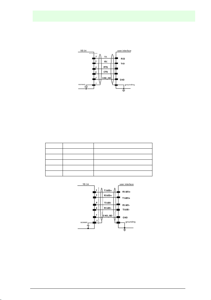
RS232 interface
In conjunction with a computer, the data of read codes and the configuration of the
reader are transmitted via this interface.
Depending on the model, the following pins the 25 or 26-pin connector are used for
the RS232 interface:
Pin Description Function
2TX Send
3RX Receive
4RTS RTS (request to send)
5CTS CTS (clear to send)
7 GND_ISO Signal ground
The RTS and CTS signals control the data transmission and ensure the
synchronisation of the two communication partners.
Subject to reasonable modifications due to technical advances. Copyright Pepperl+Fuchs, Printed in Germany
24
Pepperl+Fuchs Group • Tel.: Germany +49 621 776-0 • USA +1 330 4253555 • Singapore +65 67799091 • Internet http://www.pepperl-fuchs.com
Date of issue 06/13/2005
Barcode reader VB34
Installation
If the RTS/CTS handshake protocol is active, the VB34 reader sets the RTS output in
order to indicate that it wants to transmit a message. The receiver activates the CTS
to start the transmission.
Figure 6.12 Connection layout of the RS232 interface
RS485 interface (full duplex)
The RS485 full-duplex interface is suited for continuous (not running in dialog
operation) communication protocols in point-to-point configuration. In this case,
greater distances and a higher tolerance towards electrical interfering signals
compared with the RS232 interface can be realised.
In full-duplex operation, the RS485 interface uses the following pins of the 25-pin or
26-pin connector:
Pin Description Function
2 TX485+ RS485 output (+)
3 RX485+ RS485 input (+)
4 TX485- RS485 output (-)
5 RX485- RS485 input (-)
7 GND_ISO Signal ground
Figure 6.13 Connection layout of the RS485 interface (full duplex)
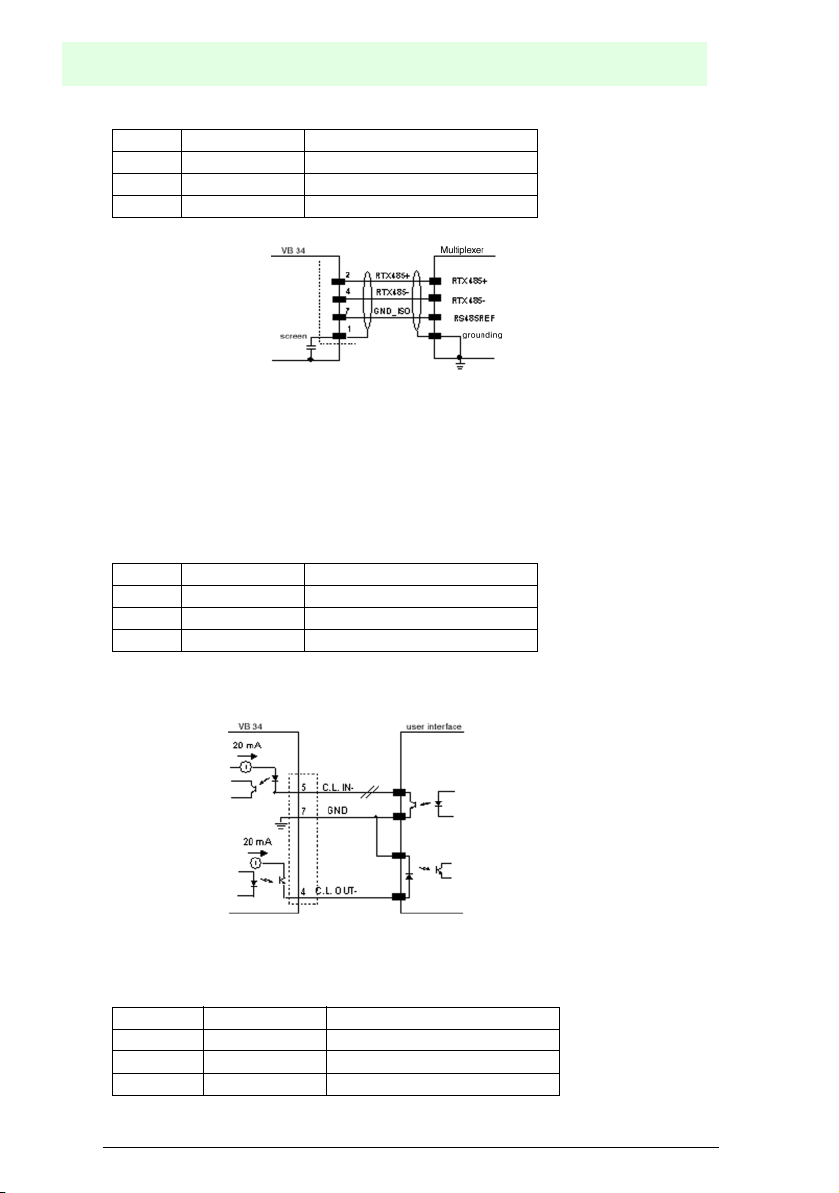
RS485 interface (half duplex)
The RS485 interface in half-duplex operation is suited for Multidrop connections with
a VISOLUX Multiplexer or for master/slave configurations.
In half-duplex operation, the RS485 interface uses the following pins of the 25-pin or
26-pin connector:
Date of issue 06/13/2005
Subject to reasonable modifications due to technical advances. Copyright Pepperl+Fuchs, Printed in Germany
Pepperl+Fuchs Group • Tel.: Germany +49 621 776-0 • USA +1 330 4253555 • Singapore +65 67799091 • Internet http://www.pepperl-fuchs.com
25
Barcode reader VB34
Installation
Pin Description Function
2 RTX485+ RS485 input/output (+)
4 RTX485- RS485 input/output (-)
7 GND_ISO Signal ground
Figure 6.14 Connection layout of the RS485 interface (half duplex)
20 mA current loop (only with INT-60 accessory option)
If the INT-60 accessory card is installed, the VB34 has a 20 mA current loop as the
interface. The INT-60 card supports the operation as passive or as active current loop,
i.e. as sink or source.
Wiring as source
In the case of an operation as source, the 26-pin connector is wired as follows:
Pin Description Function
4 CLOUT- Current loop output (-)
5 CLIN- Current loop input (-)
7 GND Grounding*
** For 20 mA current loop, GND lies on the ground potential of the
reader voltage supply.
Figure 6.15 20 mA current loop, wiring as source (active)
If the VB34 reader is connected to a C-BOX 100 via a CAB-61X0, the signals are
connected to the following terminals of the C-BOX 100:
Pin Description Function
12, 16 CLOUT- Current loop output (-)
5 CLIN- Current loop input (-)
10, 14, 19 GND Grounding*
Subject to reasonable modifications due to technical advances. Copyright Pepperl+Fuchs, Printed in Germany
26
Pepperl+Fuchs Group • Tel.: Germany +49 621 776-0 • USA +1 330 4253555 • Singapore +65 67799091 • Internet http://www.pepperl-fuchs.com
Date of issue 06/13/2005
Barcode reader VB34
Installation
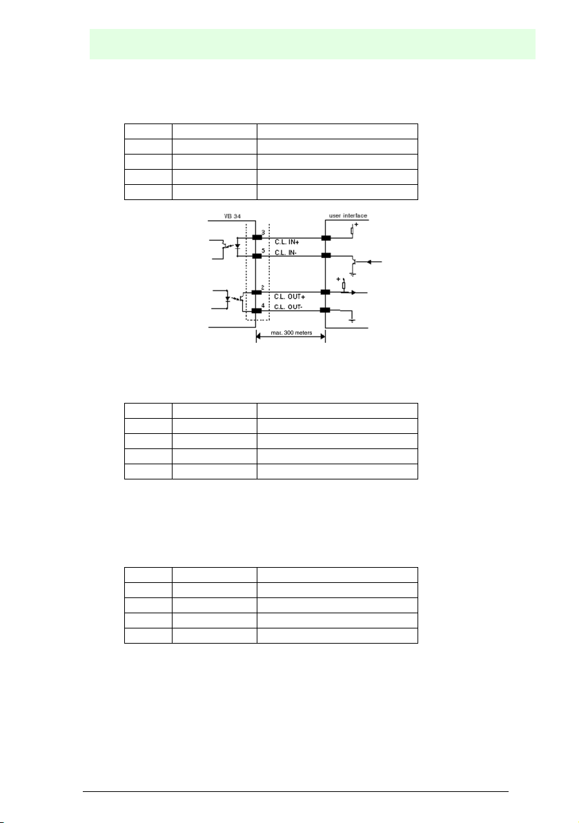
Wiring as sink
In the case of an operation as sink, the 26-pin connector is wired as follows:
Pin Description Function
2 CLOUT+ Current loop output (+)
4 CLOUT- Current loop output (-)
3 CLIN+ Current loop input (+)
5 CLIN- Current loop input (-)
Figure 6.16 20 mA current loop, wiring as sink (passive)
If the VB34 reader is connected to a C-BOX 100 via a CAB-61X0, the signals are
connected to the following terminals of the C-BOX 100:
Pin Description Function
11, 15 CLOUT+ Current loop output (+)
12, 16 CLOUT- Current loop output (-)
17 CLIN+ Current loop input (+)
18 CLIN- Current loop input (-)
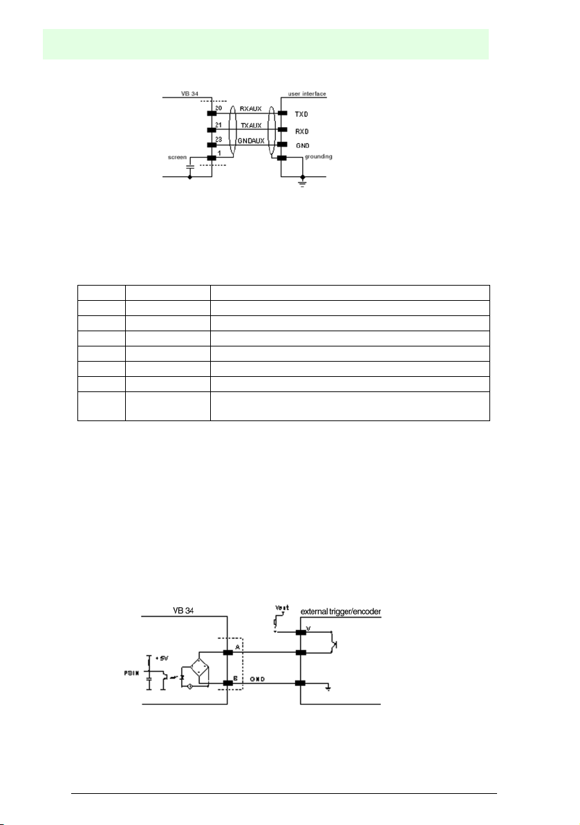
Secondary interface
The secondary serial interface is designed as a fixed RS232 full-duplex interface. The
interface is configured using the configuration software.
In full-duplex operation, the RS232 interface uses the following pins of the 25-pin or
26-pin connector:
Pin Description Function
20 RXAUX Received data
21 TXAUX Transmitted data
23 SGND AUX Signal ground
5
Date of issue 06/13/2005
Subject to reasonable modifications due to technical advances. Copyright Pepperl+Fuchs, Printed in Germany
Pepperl+Fuchs Group • Tel.: Germany +49 621 776-0 • USA +1 330 4253555 • Singapore +65 67799091 • Internet http://www.pepperl-fuchs.com
27
Barcode reader VB34
Installation
Figure 6.17 Connection layout of the RS232 interface
Inputs
The inputs of the reader are lead through on the 25-pin or 26-pin connector (Figure
6.11) of the VB34.
The inputs are labelled EXT_TRIG, IN2, IN3 and IN4.
Pin Description Function
18 EXT_TRIG A External trigger (polarity exchangeable)
19 EXT_TRIG B External trigger (polarity exchangeable)
6 IN2A Input signal 2 (polarity exchangeable)
10 IN2B Input signal 2 (polarity exchangeable)
14 IN3A Input signal 3 (polarity exchangeable)
15 IN4A Input signal 4 (polarity exchangeable)
24 IN_REF Common reference earth for IN3 and IN4 (polarity
exchangeable)
IN2 is normally used as encoder input. In the PackTrack™ operating mode, this input
is used to measure the speed of the band.
EXT_TRIG is the primary presence sensor. An active signal at this input informs the
reader that a code is to be read and decoded. A (yellow) LED indicates that the
EXT_TRIG signal is active.
IN3 and IN4 can be used as stop signal for the read cycle.
All inputs are galvanically isolated by means of optocouplers, independent of polarity
and are supplied via a constant current generator. The control signal is lead via a
debounce filter with a delay of 5 ms or 500 ms. EXT_TRIG, IN3 and IN4 work with the
same filter constant, which is usually set to 5 ms for photo cells, whereas IN2 is
operated with a filter constant of 500 ms if an encoder is connected.
Figure 6.18 Input wiring with control via PNP signal
Subject to reasonable modifications due to technical advances. Copyright Pepperl+Fuchs, Printed in Germany
28
Pepperl+Fuchs Group • Tel.: Germany +49 621 776-0 • USA +1 330 4253555 • Singapore +65 67799091 • Internet http://www.pepperl-fuchs.com
Date of issue 06/13/2005

Figure 6.19 Input wiring with control via PNP signal
Figure 6.20 Input wiring with control via NPN signal
Barcode reader VB34
Installation
Figure 6.21 Input wiring with control via NPN signal
Figure 6.22 Input wiring with control via PNP signals
Date of issue 06/13/2005
Subject to reasonable modifications due to technical advances. Copyright Pepperl+Fuchs, Printed in Germany
Pepperl+Fuchs Group • Tel.: Germany +49 621 776-0 • USA +1 330 4253555 • Singapore +65 67799091 • Internet http://www.pepperl-fuchs.com
29

Barcode reader VB34
Installation
Figure 6.23 Input wiring with control via NPN signals
The inputs can be powered via the VS signal of the reader (pin 9).
For a galvanic isolation of control and reader, however, a supply with external voltage
(Vext) instead of the voltage connected to pin 9 of the 25/26-pin connector is required.
For reasons of simplicity, the control logic for the input signals can be powered via the
supply voltage of the reader, which is connected to the pins A (VS) and B (GND) of
the connector. In this case, however, there is no galvanic isolation.
The voltage on pins A and B of the input connector is identical to the supply voltage
of the scanner.
The characteristic values of these inputs are:
Maximum voltage 30 V
Maximum current 10 mA
Outputs
Three outputs are available:
Pin Description Function
8 Out 1+ Plus lead of the digital output 1
22 Out 1- Minus lead of the digital output 1
11 Out 2+ Plus lead of the digital output 2
12 Out 2- Minus lead of the digital output 2
16 Out 3A Digital output 3 - polarity exchangeable
17 Out 3B Digital output 3 - polarity exchangeable
The function of the three outputs OUT1+, OUT2+ and OUT3+ can be defined by the
user.
Please refer to the online help for further information.
In the default setting, OUT1+ is connected with the COMPLETE READ event, which
activates the output after a code has been read correctly. If the reader was
programmed to read multiple codes in a read cycle, the event is triggered and the
output is activated after all codes have been read.
Subject to reasonable modifications due to technical advances. Copyright Pepperl+Fuchs, Printed in Germany
30
Pepperl+Fuchs Group • Tel.: Germany +49 621 776-0 • USA +1 330 4253555 • Singapore +65 67799091 • Internet http://www.pepperl-fuchs.com
Date of issue 06/13/2005

Barcode reader VB34
Installation
OUT2+ is linked with the NO READ event, which indicates that no code has been
read.
OUT3+ is linked with the NONE event, i.e. no event. This means that the output
always maintains its status.
The characteristic electrical values of the outputs OUT1+ and OUT2+ are:
Maximum collector-emitter voltage 30 V
Maximum collector current 130 mA
Saturation voltage(VCE) 1 V at 10 mA max.
Maximum power loss 90 mW at T
The limit defined by the maximum power loss is more important than the limit defined
by the maximum collector current: if one of these outputs is continuously deactivated,
the maximum current must not exceed 40 mA, even if up to 130 mA is permissible for
pulsed operation.
Figure 6.24 Connection layout of output 1 and output 2
OUT3+ is designed as a bidirectionally semiconductor relay with integrated current
limit and has thus different characteristic electrical values. At an ambient temperature
of 25°C, the maximum current through this output in continuous operation must not
exceed 200 mA, in pulsed operating, up to 300 mA is permissible. At a maximum
ambient temperature of 50°C, the maximum current is reduced to 160 mA
(continuous) and 240 mA (pulse).
The characteristic electrical values of OUT3+ are as follows:
Maximum voltage 100 V
Maximum collector current (pulse) 240 mA
R
on
R
off
6 – 15 Ohm
> 500 Ohm
Leakage current in Off status < 1 µA
Maximum power loss 550 mW in T
= 50 °C
U
= 50 °C
U
Figure 6.25 Connection layout of output 3
The control signal runs through a filter with a delay of 50 µs for OUT1+ and OUT2+
Date of issue 06/13/2005
Subject to reasonable modifications due to technical advances. Copyright Pepperl+Fuchs, Printed in Germany
Pepperl+Fuchs Group • Tel.: Germany +49 621 776-0 • USA +1 330 4253555 • Singapore +65 67799091 • Internet http://www.pepperl-fuchs.com
31

Barcode reader VB34
Installation
as well as for 1 ms for OUT3+.
If the load is powered by an external voltage supply, the voltage must be less than
30 V.
6.3.2 Lonworks connector
The network used by VB34 is based upon a Lonworks communication system, for
which only two leads (with exchangeable polarity) are required for a connection.
Furthermore, the supply voltage is lead through to the connectors. In this way, all the
slave readers can be supplied via the VISOLUX standard cable by the master.
For applications, in which an increased range of functions is required for
synchronization, the VB34 master issues two system signals with the descriptions
Sys_I/O and Sys_Enc_I/O to the slave devices. If, for example, an application works
with an encoder, the signal is received by the master and transmitted via the cable
directly to all slave devices.
The internal circuits, which generate the system signals, are powered externally via
the pins VS_I/O and REF_I/O and are galvanically isolated from the voltage supply of
the reader.
These system circuits do not have to be used in all operating modes (see section 1.7
for additional information). To ensure that the system works without errors, only
original cables and accessories should be used. The wiring must be in accordance
with the example configurations (see section 1.7 for details).
Figure 6.26 9-pin local Lonworks connectors
VB34 electrical connections of the 9-pin Lonworks connectors
Pin Description Function
1 Shield Shielding of the cable
9 VS Supply voltage - plus
2 GND Supply voltage - minus (ground)
6 VS_I/O Supply voltage of the I/O circuit
3 Ref_I/O Reference voltage of the I/O circuit
4 SYS_ENC_I/O System signal
5 SYS_I/O System signal
7 LON A Lonworks lead (polarity exchange able)
8 LON B Lonworks lead (polarity exchange able)
Subject to reasonable modifications due to technical advances. Copyright Pepperl+Fuchs, Printed in Germany
32
Pepperl+Fuchs Group • Tel.: Germany +49 621 776-0 • USA +1 330 4253555 • Singapore +65 67799091 • Internet http://www.pepperl-fuchs.com
Date of issue 06/13/2005

Barcode reader VB34
Installation
Network termination
When constructing a Lonworks system, it is important to terminate the network
correctly. For this, a BTK-6000 termination network is connected to the VB34 master
reader as well as to the last VB34 slave reader.
This termination network is equipped with two connectors and can be connected to
the 9-pin connector of the master or to the 9-pin socket of the last slave reader.
Figure 6.27 BTK-6000 termination network
For fieldbus models no external termination is required for the reader
as this is already integrated.
Note
Lonworks Interface
The Lonworks network consists of readers with input and output, which can be
connected to a multiple side or station-wide system.
Generally, the VB34 master uses the 9-pin socket as the output to the first slave
reader, while the 9-pin connector is completed with a BTK6000 termination network
(see Chapter 6.7.2 for details). With a T network configuration, both connector plugs
of the master are used for the two lead branches to the slave readers.
Both connections are always used to connect slave readers. For this purpose, the 9pin socket is used as the output and the 9-pin connector is used as the input. The
socket on the last reader is terminated to complete the network.
The following figure shows the connection of a VB34 as the master with a VB34 as
the slave reader.
Date of issue 06/13/2005
Subject to reasonable modifications due to technical advances. Copyright Pepperl+Fuchs, Printed in Germany
Pepperl+Fuchs Group • Tel.: Germany +49 621 776-0 • USA +1 330 4253555 • Singapore +65 67799091 • Internet http://www.pepperl-fuchs.com
33

Barcode reader VB34
Installation
Socket Connector
Figure 6.28 VB34 master/slave Lonworks connection
The maximum current consumption of a slave reader via the master is
2 A. Therefore, it makes sense to supply at the most 3 readers
Attention
The following figure shows the two network connections of the BTK-6000. In the
figures, the termination is shown as T. The following figure shows the switching of the
termination network.
(master + 2 slave devices) with a 24 V power pack.
Figure 6.29 Circuit diagram of the BTK-6000 termination network
The following figure shows the termination of a VB34 operated as the master with a
BTK-6000 termination network.
Figure 6.30 Termination of a VB34 master
The following figure shows the termination of a VB34 operated as the slave with a
BTK-6000 termination network.
Subject to reasonable modifications due to technical advances. Copyright Pepperl+Fuchs, Printed in Germany
34
Pepperl+Fuchs Group • Tel.: Germany +49 621 776-0 • USA +1 330 4253555 • Singapore +65 67799091 • Internet http://www.pepperl-fuchs.com
Date of issue 06/13/2005

Barcode reader VB34
Installation
Figure 6.31 Termination of a VB34 slave
The following figure shows the connection of a VB34 fieldbus model, which always
acts as the master, with a VB34 reader operated as the slave.
Figure 6.32 VB34 master/slave Lonworks connection
6.3.3 Ethernet connector
This connector is only available with VB34 Ethernet models and allows for an Ethernet
connection between the host and the reader.
Figure 6.33 RJ45 cable connector
Figure 6.34 VB34 RJ45 socket
Connector and electrical connections (see the following table) correspond to IEEE
Date of issue 06/13/2005
Subject to reasonable modifications due to technical advances. Copyright Pepperl+Fuchs, Printed in Germany
Pepperl+Fuchs Group • Tel.: Germany +49 621 776-0 • USA +1 330 4253555 • Singapore +65 67799091 • Internet http://www.pepperl-fuchs.com
802.3 10 BaseT and IEEE 802.3U 100 BaseTx.
35

Barcode reader VB34
Installation
VB34 electrical connections of the RJ45 socket
Pin Description Function
1 TX + Transmitted data (+)
2 TX - Transmitted data (-)
3 RX + Received data (+)
6 RX - Received data (-)
4, 5, 7, 8 N.C. unoccupied
Ethernet interface
The Ethernet interface (NIC) can be used for the TCP/IP-based communication with
external or local computers in a network or for the direct connection of a PC to the
reader.
The following example shows the network connection via a hub with an uncrossed
cable (standard network cable) :
Figure 6.35 Uncrossed cable
The following example shows the direct connection of the reader to a PC with a
crossover cable:
Figure 6.36 Crossover cable
For additional information, refer to document “Ethernet.pdf”, which is available as
additional documentation.
Subject to reasonable modifications due to technical advances. Copyright Pepperl+Fuchs, Printed in Germany
36
Pepperl+Fuchs Group • Tel.: Germany +49 621 776-0 • USA +1 330 4253555 • Singapore +65 67799091 • Internet http://www.pepperl-fuchs.com
Date of issue 06/13/2005

Barcode reader VB34
6.3.4 DeviceNet connector
When the DeviceNet is used, the primary serial interface is
deactivated and must not be interfaced with another device.
Note
The 5-pin connector is only available with the DeviceNet model of the VB34 and
allows for a connection between the reader and a higher-level system:
Figure 6.37 5-pin DeviceNet connector
VB34 electrical connections of the 5-pin DeviceNet connector
Pin Description Function
2 V + Supply voltage - plus
5 CAN_L CAN bus data lead – L
1 Shield Shield
4 CAN_H CAN bus data lead – H
3 V - Supply voltage - minus
Installation
The supply voltage to the pins V+ and V- is only used to supply the
part of the DeviceNet card, which is directly connected to the bus. It is
galvanically isolated from the supply of the VB34, which has to be
Note
connected to the pins 9 and 13 as well as 23 and 25 of the 26-pin
connector.
6.3.5 Profibus connector
The 9-pin Profibus socket is only available with the Profibus model of the VB34 and
allows for a connection between the reader and a higher-level system:
Figure 6.38 9-pin Profibus socket
Date of issue 06/13/2005
Subject to reasonable modifications due to technical advances. Copyright Pepperl+Fuchs, Printed in Germany
Pepperl+Fuchs Group • Tel.: Germany +49 621 776-0 • USA +1 330 4253555 • Singapore +65 67799091 • Internet http://www.pepperl-fuchs.com
37

Barcode reader VB34
Installation
VB34 electrical connections of the 9-pin Profibus socket
Pin Description Function
1 Shield* Shield or protective earth
2 - unoccupied
3 B-LINE (RXD/TXD-P) Received / transmitted data P
4 CNTR-P** Repeater control signal
5 DGND Signal ground (M5V)
6 +5 V 5 V voltage plus (P5V)
7 - unoccupied
8 A-LINE (RXD/TXD-N) Received / transmitted data
9 CNTR-N** Repeater control signal
* optional
** optional, RS485 level
Profibus interface
The Profibus interface is used for communication with a higher-level system and
allows for an extended network and remote diagnosis functionality of the reader.
For additional information, refer to the document “Profibus_Fam6k.pdf”, which is
available as additional documentation.
6.3.6 Voltage supply
The supply voltage of an individual reader must lie between 15 and 30 V DC.
In master/slave configurations, VISOLUX recommends a voltage supply with at least
24 V DC.
The power consumption of the different VB34 models is slightly different.
When several VB34 readers are connected in a master/slave configuration, the
maximum power consumption per reader is 15 W. Starting the motor results in a peak
demand of approx. 20 W for 5 to 10 seconds.
Figure 6.39 Voltage supply via the 25-/26-pin connector
Subject to reasonable modifications due to technical advances. Copyright Pepperl+Fuchs, Printed in Germany
38
Pepperl+Fuchs Group • Tel.: Germany +49 621 776-0 • USA +1 330 4253555 • Singapore +65 67799091 • Internet http://www.pepperl-fuchs.com
Date of issue 06/13/2005

Barcode reader VB34
6.4 Operator interface
RS232 connection assignment to the PC
9-pin connector 25-pin connector
Pin Description Pin Description
2RX3RX
3TX2TX
5 GND 7 GND
7 RTS 4 RTS
8CTS5CTS
How to set up a simple test cable:
The following figure shows a simple test cable with supply, an external trigger (push
button) and the connection of the RS232 interface to a PC.
Installation
Figure 6.40 VB34 test cable
6.5 Adjusting the reader
The VB34 reader is able to read labels at most angles, however, a strong distortion
can have an unfavourable effect on reading performance.
When assembling the VB34, note the following three ideal angles for the label
position:
Tilt angle 0°, angle of rotation 10° to 30° and rotation 0°.
Follow the proposals in the next paragraph how best to position the reader:
The tilt angle is represented by the value P, see figure 41. Adjust the reader in such
a way that the tilt angle is held as low as possible.
Date of issue 06/13/2005
Subject to reasonable modifications due to technical advances. Copyright Pepperl+Fuchs, Printed in Germany
Pepperl+Fuchs Group • Tel.: Germany +49 621 776-0 • USA +1 330 4253555 • Singapore +65 67799091 • Internet http://www.pepperl-fuchs.com
39

Barcode reader VB34
Installation
Figure 6.41 Tilt angle
The angle of rotation is represented by the value S, see figure 42. Adjust the reader
in such a way that the angle of rotation is at least 10°. This prevents a direct
reflection of the laser beam emitted by the reader.
With oscillating mirror models, this angle mirrors the smallest deflection or the
scanning line that is closest to the horizontal. All other scanning lines have an angle
of rotation of more than 10°.
Figure 6.42 Angle of rotation
The tilt angle is represented by the value T, see Figure 6.43.
Figure 6.43 Tilt angle
Subject to reasonable modifications due to technical advances. Copyright Pepperl+Fuchs, Printed in Germany
40
Pepperl+Fuchs Group • Tel.: Germany +49 621 776-0 • USA +1 330 4253555 • Singapore +65 67799091 • Internet http://www.pepperl-fuchs.com
Date of issue 06/13/2005

Barcode reader VB34
6.6 Typical installations
6.6.1 Standard installation
The VB34 reader is fitted on a ST-237 mounting angle with 105° (see figure 4), which
ensures an angle of rotation (S in the following figure) of 15° to the level of the image.
(Generally, the angle of rotation should lie between 10° and 20°.) This prevents a
direct reflection of the laser beam emitted by the reader. Furthermore, the mounting
angle allows for an adjustment of the tilt angle (T in the following figure, generally 0°)
for an optimum alignment of the reader:
Figure 6.44 Standard installation
Installation
6.6.2 Installation with an angle of rotation of 45°
The VB34 reader is fixed with a ST-210 90° mounting angle (Figure 6.6). Adjust the
guides of the mounting angle in such a way that an angle of rotation (S in the following
figure) 45° is achieved in order to avoid a direct reflection from the laser beam
emanated from the reader.
Figure 6.45 Installation with an angle of rotation of 45°
Date of issue 06/13/2005
Subject to reasonable modifications due to technical advances. Copyright Pepperl+Fuchs, Printed in Germany
Pepperl+Fuchs Group • Tel.: Germany +49 621 776-0 • USA +1 330 4253555 • Singapore +65 67799091 • Internet http://www.pepperl-fuchs.com
41

Barcode reader VB34
Installation
With the installation with an angle of rotation of 45° it is not ensured
that the reader will achieve the same efficiency (see reading fields in
Attention
Note
6.7 Typical hardware configurations
The following sections show typical examples for the system hardware configurations,
for which a corresponding software configuration is required. For more detailed
information, please refer to Chapter 7.2.
For other hardware configurations, a VB34 reader with a special decoder base
assembly may be required.
The illustrated cable and accessories are original products. To ensure the functional
capability and smooth operability of the system, it is recommended that you only use
these products.
6.7.1 Point-to-point
In a point-to-point arrangement, the data is transmitted both via the primary and
secondary interface. The primary interface can be adjusted to the full-duplex
communication in accordance with the RS232 or RS485 standard.
Depending on the VB34 model, various hardware configurations are possible.
Figure 8.3.1) as in the standard installation with angles of rotation
between 10° and 20°.
The mounting angle ST-210 is contained as an accessory for the
VB34 standard model in the US-60 set.
Master/slave models
During online operation, the reader is activated by an external trigger (light barrier)
when an object enters the reading zone. In the following example, the signal is
created via a C-BOX 100 to the VB34 reader, which also supplies the system.
*) Presence sensor connected to the external trigger input.
Figure 6.46 Point-to-point arrangement for master/slave models
Subject to reasonable modifications due to technical advances. Copyright Pepperl+Fuchs, Printed in Germany
42
Pepperl+Fuchs Group • Tel.: Germany +49 621 776-0 • USA +1 330 4253555 • Singapore +65 67799091 • Internet http://www.pepperl-fuchs.com
Date of issue 06/13/2005

Barcode reader VB34
Fieldbus models
In this case, no external trigger is used. The C-BOX 100 is used only to supply the
reader. The VB34 reader (as an Ethernet, DeviceNet or Profibus model) is connected
to an external fieldbus host. It can be activated by a signal from the external host or
always be active in automatic operation mode.
*) Light barrier (presence sensor) connected to the external trigger input .
Figure 6.47 Point-to-point arrangement for fieldbus models
6.7.2 Loops
With the loop arrangement via the secondary interface, all VB34 models can be
integrated into a network with different readers, without the need for a Lonworks
interface.
In this loop arrangement, two or more readers can be connected to a single external
serial interface. Each VB34 reader also provides the messages, which it received on
the secondary (RS232) interface, via the primary interface (also RS232).
In this arrangement, several readers can be switched in series. The message passes
through all the stations in the chain up to the host. The read cycles of the individual
readers are independent of those of the other readers. In loop configurations, each
reader has an own external trigger (several light barriers).
For this purpose, a portable reader can also be included via the secondary serial
interface in order to read codes manually.
The maximum cable length for RS232 connections is 15 m.
The following figure shows several VB34 readers in a loop arrangement.
Installation
Date of issue 06/13/2005
Subject to reasonable modifications due to technical advances. Copyright Pepperl+Fuchs, Printed in Germany
Pepperl+Fuchs Group • Tel.: Germany +49 621 776-0 • USA +1 330 4253555 • Singapore +65 67799091 • Internet http://www.pepperl-fuchs.com
43

Barcode reader VB34
Installation
*) Light barrier (presence sensor) connected to the external trigger input .
Figure 6.48 Loop arrangement for VB34 master/slave models
*) Light barrier (presence sensor) connected to the external trigger input .
(1) Primary serial interface
(2) Secondary serial interface
Figure 6.49 Loop arrangement for fieldbus models
Subject to reasonable modifications due to technical advances. Copyright Pepperl+Fuchs, Printed in Germany
44
Pepperl+Fuchs Group • Tel.: Germany +49 621 776-0 • USA +1 330 4253555 • Singapore +65 67799091 • Internet http://www.pepperl-fuchs.com
Date of issue 06/13/2005

Barcode reader VB34
6.7.3 RS232 master/slave
In the RS232 master/slave arrangement, all VB34 models can be integrated into a
network with different readers, without the need for a Lonworks interface.
The readers operated as the slave only communicate via the primary and secondary
RS232 interfaces. Each slave device also provides the messages, which it received
on the secondary interface, via the primary interface. All messages are transmitted to
the master.
The master reader is connected via the primary RS232 interface and a C-BOX 100 to
a computer. If the INT-60 accessory option is installed, a 20 mA current loop can be
used.
For the RS232 master/slave arrangement, a central external trigger signal is used (a
light barrier).
The VB34 reader (master/slave variant only), which is used as the
Note
master in a RS232 network
Lonworks network
with VB34 slave readers. When assigning slave
addresses, note that the number of the first Lonworks slave must
follow on seamlessly to the number of the last slave reader in the
RS232 network. If, for example, the RS232 network consists of the
devices slave 1 and slave 2 , the first slave device in the Lonworks
network is slave 3 (not slave 1).
, can simultaneously be connected to a
Installation
*) Light barrier (presence sensor) connected to the external trigger input .
(1) Primary serial interface
(2) Secondary serial interface
Figure 6.50 RS232 master/slave for VB34 master/slave models
Date of issue 06/13/2005
Subject to reasonable modifications due to technical advances. Copyright Pepperl+Fuchs, Printed in Germany
Pepperl+Fuchs Group • Tel.: Germany +49 621 776-0 • USA +1 330 4253555 • Singapore +65 67799091 • Internet http://www.pepperl-fuchs.com
45

Barcode reader VB34
Installation
*) Light barrier (presence sensor) connected to the external trigger input .
(1) Primary serial interface
(2) Secondary serial interface
Figure 6.51 RS232 master/slave for VB34 master/slave fieldbus models
6.7.4 Multiplexer
The Multiplexer layout serves to integrate VB34 slave readers into a Multidrop
network, which consists of different readers without a Lonworks interface .
All the readers are connected via the primary interface to a Multiplexer.
In this instance, the primary interface is configured as the RS485 half duplex
interface.
Subject to reasonable modifications due to technical advances. Copyright Pepperl+Fuchs, Printed in Germany
46
Pepperl+Fuchs Group • Tel.: Germany +49 621 776-0 • USA +1 330 4253555 • Singapore +65 67799091 • Internet http://www.pepperl-fuchs.com
Date of issue 06/13/2005

*) Light barrier (presence sensor) connected to the external trigger input .
(1) Primary serial interface
Figure 6.52 Multiplexer for VB34 master/slave models
The secondary serial interface of the slave readers can be used to visualize the
entered data or to configure via the configuration software.
During online operation, the reader is activated by an external trigger (light barrier)
when an object enters the reading zone.
6.7.5 Local Lonworks network
In a local Lonworks network, up to 31 VB34 slave devices can be connected to a
VB34 master reader. In real terms, the number of readers that can be used in the
network depends on the system operating conditions, especially on the operating
mode and the volume of data. The online operating mode (for additional information,
see the configuration software online help) supports, for example, a maximum of 8
slave readers.
With regard to the design of your network, always consider the following points:
• from an electrical point of view, the network supports up to 31 VB34 readers with a
network length of 130 m.
• the maximum number of supported VB34 readers depends on how the system
components are supplied. (For additional information, refer to Chapter 6.3.6.)
Contact VISOLUX if you have to integrate a large number of readers into your network
or if the data throughput in the application is extremely high.
When you construct the network, the VB34 master reader must be connected via the
25-pin Sub-D connector to a local computer or to C-BOX 100.
The first slave reader of the system is connected to the 9-pin Lonworks socket of the
master, while the 9-pin Lonworks connector must be completed with a BTK-6000
Date of issue 06/13/2005
termination network.
Barcode reader VB34
Installation
Subject to reasonable modifications due to technical advances. Copyright Pepperl+Fuchs, Printed in Germany
Pepperl+Fuchs Group • Tel.: Germany +49 621 776-0 • USA +1 330 4253555 • Singapore +65 67799091 • Internet http://www.pepperl-fuchs.com
47

Barcode reader VB34
Installation
The slave readers are connected together via the Lonworks connector plug. The
network must be completed with a BTK-6000 termination network on the 9-pin socket
of the last slave reader.
Central light barrier
The presence sensor is connected to the C-BOX 100 and is used as the sole, central
trigger source in the system. There is only one read cycle with a message from the
master reader to the local host. The online operating mode is used in this layout.
*) Presence sensor connected to the external trigger input.
Figure 6.53 Central light barrier with 2 readers
The following figure shows a system with four readers, which are supplied via two
power packs. The master reader receives the external signals (triggers, serial host
signals, etc.) and is supplied together with slave 1 by the first power pack via a C-BOX
100, while slave 2 and slave 3 are connected via a C-BOX 100 and the CAB610X
cable to a second power pack. Each power pack supplies up to 2 readers. The
CAB611X cable connects two separate groups: master and slave 1 as well as slave
2 and slave 3. In this instance, the voltage supply is not continued, only the network
and synchronization signals are continued.
Subject to reasonable modifications due to technical advances. Copyright Pepperl+Fuchs, Printed in Germany
48
Pepperl+Fuchs Group • Tel.: Germany +49 621 776-0 • USA +1 330 4253555 • Singapore +65 67799091 • Internet http://www.pepperl-fuchs.com
Date of issue 06/13/2005

Barcode reader VB34
Installation
*) Light barrier (presence sensor) connected to the external trigger input .
**) The power pack can be connected directly via a separate cable to slave 2
(2 wires with at least 0,5 mm² for VS + GND).
Figure 6.54 Central light barrier with more than 2 readers and several power packs
The following figure shows a system with five readers, in which the master reader
receives the external signals (triggers, serial host signals, etc.) and is supplied
together with slave 1 and slave 2 via a C-BOX 100, while slave 3 and slave 4 are
connected via a CAB610X cable to a second power pack. This is necessary because
the C-BOX 100 can supply a maximum of 3 readers. The CAB611X cable connects
two separate groups: master, slave 1 and slave 2 as well as slave 3 and slave 4. In
this instance, the voltage supply is not continued, only the network and
synchronization signals are continued.
Slave 3 is connected via a customer-specific, 2-wire cable (0,5 mm²) to the power
pack (VS + GND).
*) Light barrier (presence sensor) connected to the external trigger input .
Figure 6.55 Central light barrier with more than 2 readers and central voltage supply
Date of issue 06/13/2005
Subject to reasonable modifications due to technical advances. Copyright Pepperl+Fuchs, Printed in Germany
Pepperl+Fuchs Group • Tel.: Germany +49 621 776-0 • USA +1 330 4253555 • Singapore +65 67799091 • Internet http://www.pepperl-fuchs.com
49

Barcode reader VB34
Installation
Multiple light barrier (configuration available shortly).
In this layout, up to 7 VB34 slave readers each have a separate light barrier and thus
several read cycles. The light barrier, which controls the master reader, is connected
via the C-BOX 100.
The master transmits all the messages received via the Multidrop lead as well as its
own messages to the C-BOX 100, which forwards them to the local host.
The following figure shows a system with four readers, in which the fourth reader is
supplied via a separate C-BOX 100 because a C-BOX 100 can supply a maximum of
3 readers. Therefore, the cable connecting the two separate groups does not carry
over the supply. In this example, this is cable CAB611X between slave 2 and slave 3.
*) Light barrier (presence sensor) connected to the external trigger input .
Figure 6.56 Multiple light barrier with more than 3 readers
6.7.6 Fieldbus network
Fieldbus models (Ethernet, Profibus and DeviceNet) enable communication in
fieldbus environments without a converter or adapter.
The VB34 fieldbus master communicates with the external host via a cable, which is
connected to the fieldbus connector (Ethernet, Profibus or DeviceNet). This host can,
for example, be an external PC with an IP address.
The 9-pin Lonworks socket is used to connect the first slave device to the master,
while the 26 Sub-D connector is used to supply the master via a C-BOX 100.
The slave readers (VB34 master/slave models) are connected together via the
Lonworks connector plug. The network must be completed with a BTK-6000
termination network on the 9-pin socket of the last slave reader. No termination
network is required for the fieldbus master because the termination is already
integrated.
Subject to reasonable modifications due to technical advances. Copyright Pepperl+Fuchs, Printed in Germany
50
Pepperl+Fuchs Group • Tel.: Germany +49 621 776-0 • USA +1 330 4253555 • Singapore +65 67799091 • Internet http://www.pepperl-fuchs.com
Date of issue 06/13/2005

Barcode reader VB34
Installation
Central light barrier
The VB34 master reader (as an Ethernet, DeviceNet or Profibus model) is connected
to an external fieldbus host. It can be activated by a signal from the external host or
always be active in automatic operation mode.
*) Light barrier (presence sensor) connected to the external trigger input .
Figure 6.57 Fieldbus layout with a central light barrier
As already described, a C-BOX 100 can supply a maximum of 3 readers. If more than
3 readers are used, connect the different groups with a CAB611X cable, which does
not loop in the supply lines, and supply the individual groups separately.
6.8 FLASH™ dynamic focusing
An innovation of the VB34 is the linear motor, which can be used to control the reading
position of the scanner via software. This dynamic system with the name Flash™ is
able to assume any reading position from the minimum position to the maximum
position.
The Flash™ function is programmed via the configuration software (see the online
help for details) and has the following operating modes:
• Fixed adjustment
• Continuous adjustment
• Trigger operating mode
• D-Flash™ operating mode
Date of issue 06/13/2005
Subject to reasonable modifications due to technical advances. Copyright Pepperl+Fuchs, Printed in Germany
Pepperl+Fuchs Group • Tel.: Germany +49 621 776-0 • USA +1 330 4253555 • Singapore +65 67799091 • Internet http://www.pepperl-fuchs.com
51

Barcode reader VB34
Installation
6.8.1 Fixed adjustment
With fixed adjustment, the read distance (in cm/inch) is adjusted as fixed to the
desired position per software. This is the most simple Flash™ function, during which
the focus position is adjusted per software before use in the application and stored in
the decoder of the reader. This function is similar to the focus adjustment of the VB33
reader, however, with the major difference that in terms of software the adjustment is
made using the configuration program and not manually via an adjustment screw.
Figure 6.58 Flash™ fixed adjustment
6.8.2 Continuous adjustment
With continuous adjustment, the focus position is continuously adjusted with a defined
frequency (f1 in the following figure) between minimum and maximum. This Flash™
function makes it possible to use the entire read range of the VB34 if the objects to be
recognized are large and move slowly. Typical areas of application for continuous
adjustment are reading the front of large pallets or objects on a fork lift truck.
Figure 6.59 Flash™ continuous adjustment
6.8.3 Trigger operating mode
In the trigger operating mode, the focus position is adjusted depending on an external
input signal (light barrier, message via the serial interface…). This is the traditional
Flash™ function, for which light barriers or a separate interface to the host (PC or
PLC) are required. The excellent capability of the VB34 optical system platform
makes it possible to cover an area of 800 mm x 800 mm with a code resolution of
38 mm using only one light barrier.
Subject to reasonable modifications due to technical advances. Copyright Pepperl+Fuchs, Printed in Germany
52
Pepperl+Fuchs Group • Tel.: Germany +49 621 776-0 • USA +1 330 4253555 • Singapore +65 67799091 • Internet http://www.pepperl-fuchs.com
Date of issue 06/13/2005

Barcode reader VB34
Figure 6.60 Flash™ trigger operating mode
6.8.4 D-Flash™ operating mode
In the D-Flash™ operating mode, the focus position is changed depending on the
measured distance (Dn in the following figure) between the reader and the object to
be read. This innovative and highly flexible function presents the software with
extensive possibilities. The D-Flash™ development is based upon the measured
minimum distance. This makes it suitable for a variety of applications. If necessary,
D-Flash™ can be tailored to meet the requirements of a specific application and
developed further.
Installation
Figure 6.61 Flash™ D-Flash™ operating mode
6.9 Key field and display
The VB34 key field makes it possible to call a menu using the following functions:
• Internal Net
• Test mode
These adjustments can also be made via the configuration software. (For additional
information, refer to Chapter 7.)
6.9.1 Internal Net
This sub menu is used to configure the VB34 reader in a master/slave network.
Here, the function of the reader (slave/master) in the network as well as, if configured
as a slave, the address are defined.
To call the Internal Net sub menu and configure the reader, carry out the following
steps:
1. Keep the keys
the same time to call the main menu.
2. Press the key
option and press ENT (Enter) to call the option.
3. Press the keys
menu option and press ENT (Enter) to call the option.
Date of issue 06/13/2005
Subject to reasonable modifications due to technical advances. Copyright Pepperl+Fuchs, Printed in Germany
Pepperl+Fuchs Group • Tel.: Germany +49 621 776-0 • USA +1 330 4253555 • Singapore +65 67799091 • Internet http://www.pepperl-fuchs.com
4. Select the reader function using the keys
▲ (arrow up) and ▼ (arrow down) depressed for 2 seconds at
▲ (arrow up) or ▼ (arrow down) to select the “Internal Net ” menu
▲ (arrow up) or ▼ (arrow down) to select the “LonWAddrSel”
▲ (arrow up) and ▼ (arrow down):
53

Barcode reader VB34
Software configuration
“MASTER” for master, “Slave n” for slave or “Disabled” for deactivated. Press the
key ENT (Enter) to call the option.
5. Press the key
and press ENT (Enter) to call the option. Repeat this step to exit the main menu
and to return to the originally active operating mode of the reader.
6.9.2 Test mode
The test mode is very useful during the installation phase because the reader is
activated to check the optical adjustments as well as the reading position of the
barcodes.
To call the Test Mode sub menu and configure the reader, carry out the following
steps:
1. Keep the keys
the same time to call the main menu.
2. Press the key
option and press ENT (Enter) to call the option. The reader switches to test
mode.
3. Press the key
4. Press the key
and press ENT (Enter) to call the option. The reader exits the main menu and
returns to the previous operating mode.
7 Software configuration
7.1 Software installation
The new configuration software offers a number of important special features:
• Assistant-based approach for less experienced users
• Multi-lingual version
• Defined configuration is stored directly in the reader.
• A communication protocol independent of the used interface allows for the hard-
ware-independent treatment of the reader as an external object, which is configured and monitored.
To install the software, carry out the following steps:
1. Switch on the PC, on which the configuration software is to be used, and start
Windows.
2. Insert the CD-ROM into the drive.
3. Wait until the installation program from the CD has started and then follow the
installation procedure.
▲ (arrow up) or ▼ (arrow down) to select the “Exit” menu option
▲ (arrow up) and ▼ (arrow down) depressed for 2 seconds at
▲ (arrow up) or ▼ (arrow down) to select the “Test Mode” menu
▲ (arrow up) to exit the test mode.
▲ (arrow up) or ▼ (arrow down) to select the “Exit” menu option
Subject to reasonable modifications due to technical advances. Copyright Pepperl+Fuchs, Printed in Germany
54
Pepperl+Fuchs Group • Tel.: Germany +49 621 776-0 • USA +1 330 4253555 • Singapore +65 67799091 • Internet http://www.pepperl-fuchs.com
Date of issue 06/13/2005

Barcode reader VB34
Software configuration
7.2 Hints on quick configuration
7.2.1 Assistant for quickly setting up the reader
After installing the configuration software (Chapter 7.1) the system displays the
following window in which the user can select the desired configuration type:
Figure 7.1 Start window for configuration program
Less experienced users should select the option "Wizard", where an Assistant will
guide you step by step through the configuration of the reader. The following
parameters must be defined:
• Selection and definition of the barcodes
• Selection and definition of the operating mode (for more information, see the following sections)
• Configuration of the digital inputs/outputs
• Selection of the hardware interface
• Configuration of the data output format
After the parameters have been defined, the system displays the following window for
completing the configuration of the reader with the following options:
• Save configuration on disk
• Change to enhanced configuration
• Send configuration to the reader
Date of issue 06/13/2005
Subject to reasonable modifications due to technical advances. Copyright Pepperl+Fuchs, Printed in Germany
Pepperl+Fuchs Group • Tel.: Germany +49 621 776-0 • USA +1 330 4253555 • Singapore +65 67799091 • Internet http://www.pepperl-fuchs.com
55

Barcode reader VB34
Software configuration
Figure 7.2 Completion window of the Configuration Assistant
Test operating mode
Figure 7.3 Selecting the test operating mode
In the test mode, the reader is continuously activated in order to check the optical
adjustments as well as the reading position of the barcodes. This operating mode
should be used during the installation phase of the reader.
After 100 read processes, the read data and an internal counter are displayed and
output via the serial interface. The counter contains the percentage of the successful
read processes.
Subject to reasonable modifications due to technical advances. Copyright Pepperl+Fuchs, Printed in Germany
56
Pepperl+Fuchs Group • Tel.: Germany +49 621 776-0 • USA +1 330 4253555 • Singapore +65 67799091 • Internet http://www.pepperl-fuchs.com
Date of issue 06/13/2005

Barcode reader VB34
Software configuration
Online operating mode
Figure 7.4 Selecting the online operating mode
This operating mode instructs the reader to evaluate the external presence sensor at
the input EXT TRIG+ and EXT TRIG.
If the presence sensor is active, the VB34 reader attempts to enter and decode the
code.
If the decoding cycle is completed successfully, the barcode data is transmitted via
the serial interface. Otherwise, a message stating that no data was read is
transmitted.
Automatic operating mode
Figure 7.5 Selecting the automatic mode
No connection to an external presence sensor is required for this operating mode. In
this operating mode, the reader scans automatically and activates the read cycle
when a barcode enters the read zone of the reader. The reader stops after an
adjustable number of empty scans.
The barcode data is transmitted via the serial Interface. If a read cycle is completed
without a result, no message is transmitted to the computer.
Date of issue 06/13/2005
Subject to reasonable modifications due to technical advances. Copyright Pepperl+Fuchs, Printed in Germany
Pepperl+Fuchs Group • Tel.: Germany +49 621 776-0 • USA +1 330 4253555 • Singapore +65 67799091 • Internet http://www.pepperl-fuchs.com
57

Barcode reader VB34
Software configuration
7.2.2 Network Assistant
The Network Assistant allows you to define the models and number of slave readers
in the Lonworks network.
The configuration software identifies the device type by means of a code number. The
code number is displayed in the relevant device window.
The following code numbers are assigned to the device types:
Device type Code number
VB33-2000-XX DS6300-100-XXX
VB33-2000-OM-XX DS6300-105-XXX
VB34-2500-XX DS6400-100-XXX
VB34-2500-OM-XX DS6400-105-XXX
Since this tool is only available for a VB34 master, your reader must first be configured
as the master as shown in the following figure:
Figure 7.6 Network setting of the local device
After that, the network settings can be defined by starting the Network Assistant:
1. If the Assistant cannot be started, activate the cluster configuration by clicking
the symbol in the toolbar. After that, the “Devices” device window will appear next to the Explorer window parameter.
Figure 7.7 Cluster configuration
Subject to reasonable modifications due to technical advances. Copyright Pepperl+Fuchs, Printed in Germany
58
Pepperl+Fuchs Group • Tel.: Germany +49 621 776-0 • USA +1 330 4253555 • Singapore +65 67799091 • Internet http://www.pepperl-fuchs.com
Date of issue 06/13/2005

Barcode reader VB34
Software configuration
2. Click the push button in the “Devices” device window in order to
open the dialog field of the Network Assistant:
Figure 7.8 Network Assistant
a) If the slave readers are already configured and wired with the network, click
the autodetect button in order to start the network query. All the devices that
were found are listed in the “Current Devices” area. From the “Current
Devices” area, select the desired slave reader and click the symbol in
order to transfer the reader to the “Requested Devices” area in which you
configure the network. You can also drag and store the device into this area
by keeping the mouse button depressed.
b) If the slave readers have not yet been configured and connected to the
network, click the symbol in order to add a new device to the
configuration. During this process, you also have to enter the model and
device address. The slave reader you added will then appear in the “Current
Devices” area.
3. If you want, select the transferred/added slave readers in the “Requested
Devices” area and click the symbol in order to edit the description of the
reader.
4. After your network has been configured, close the Network Assistant. Before
closure, the program shows a dialog field containing the query whether you
would like transmit the new configuration to the master. Select the option “Yes”
in order to start this operation.
7.3 Enhanced configuration
The ADVANCED option at the start of the configuration program is directed at
experienced users, who would like to configure the reader in all details without the
Assistant. After selecting this option, you can create a new reader configuration or
open or change an existing one. The parameters are defined in the following window,
which contains an Explorer-like organization structure:
Date of issue 06/13/2005
Subject to reasonable modifications due to technical advances. Copyright Pepperl+Fuchs, Printed in Germany
Pepperl+Fuchs Group • Tel.: Germany +49 621 776-0 • USA +1 330 4253555 • Singapore +65 67799091 • Internet http://www.pepperl-fuchs.com
59

Barcode reader VB34
Software configuration
Figure 9 - Parameters in the Explorer window
If required, to help you make the setting, an Online help is available, which is
represented in an HTML browser.
It is called via the configuration help option in the help menu. Furthermore, after
selecting the desired parameter, a context-sensitive help is available via the <F1>
key.
7.4 Basic settings for parameters
The following table describes the default settings for VB34.
The configuration software also allows the current parameter settings to be compared
with the default settings. In the Tools menu. select the "Compare parameters" option
in order to compare the current configuration with the default setting.
Subject to reasonable modifications due to technical advances. Copyright Pepperl+Fuchs, Printed in Germany
60
Pepperl+Fuchs Group • Tel.: Germany +49 621 776-0 • USA +1 330 4253555 • Singapore +65 67799091 • Internet http://www.pepperl-fuchs.com
Date of issue 06/13/2005

Date of issue 06/13/2005
Barcode reader VB34
Software configuration
Parameters Basic setting
Code definition
Code combination
Message if read process without result
String if read process without result
Label code settings no. 1
Code symbology
Length of label
Minimum of code position
Maximum of code position
Check digit
Decoding complexity
Comparison string
Label code settings no. 2
Code symbology
Length of label
Minimum for label length
Maximum for label length
Minimum of code position
Maximum of code position
Check digit
Decoding complexity
Comparison string
Operating modes
Operating mode selection
Online options
Start input number
Active level for start input
Timeout for read cycle
Statistical data
Read system layout
Device assignment Independent
Read parameters
Beam lock
Overflow relationship
Read operating mode
Reconstruction parameters
Max. scan gaps
Max. stack codes
Scan lines amplitude
Release of amplitude setting Deactivated
Single label
Global message if read process
without result
<CAN>
Interleaved 2 from 5
8
0
255
Deactivated
3
Empty
Code 39
Variable
1
48
0
255
Deactivated
3
Empty
Online
Online input 1
1
Active when closed
Deactivated
Deactivated
Deactivated
7
Reconstruction
5
1
Subject to reasonable modifications due to technical advances. Copyright Pepperl+Fuchs, Printed in Germany
Pepperl+Fuchs Group • Tel.: Germany +49 621 776-0 • USA +1 330 4253555 • Singapore +65 67799091 • Internet http://www.pepperl-fuchs.com
61

Barcode reader VB34
Software configuration
Parameters Basic setting
Flash
Flash operating mode Deactivated
Data communication settings
Host application protocol type Standard
Data format
Send start section
Termination string after message with reading
without results
Trigger selection for sending the message
Parameters
Opening text
Code direction ID
Code ID
Termination string
Separators for data packets
Setting for code field length
Primary serial interface
Transmitted data
Parameters
Communication type of primary interface
Interface standard of primary interface
Handshake
Baud rate
Parity
Data bits
Stop bits
Secondary serial interface
Transmitted data
Loop
Parameters
Baud rate
Parity
Data bits
Stop bits
With data
Activated
After decoding
<STX>
Deactivated
Deactivated
<CR><LF>
<CR><LF>
Variable length
Activated
Standard
RS232
off
9600
none
8
1
Activated
Deactivated
115200
off
8
1
Subject to reasonable modifications due to technical advances. Copyright Pepperl+Fuchs, Printed in Germany
62
Pepperl+Fuchs Group • Tel.: Germany +49 621 776-0 • USA +1 330 4253555 • Singapore +65 67799091 • Internet http://www.pepperl-fuchs.com
Date of issue 06/13/2005

Barcode reader VB34
Optical properties
Parameters Basic setting
Settings for digital inputs/outputs
Filter settings of digital inputs
Anti-disturbance hardware for inputs 1, 3 and 4
Anti-disturbance hardware for input 2
Operating mode has priority before active input
1
Operating mode has priority before active input
2
Operating mode has priority before active input
3
Operating mode has priority before active input
4
Output 1
Lead status
Activating event
Alternative activating event
Deactivating event
Alternative deactivating event
Deactivating timeout (ms)
Output 2
Lead status
Activating event
Alternative activating event
Deactivating event
Alternative deactivating event
Deactivating timeout (ms)
Output 3
Lead status
Activating event
Alternative activating event
Deactivating event
Alternative deactivating event
5 ms
500 µs
Active when closed
Active when closed
Active when closed
Active when closed
NC
Reading completed
Repeated reading
Timeout
off
50
NC
Reading without result
Partial reading
Timeout
off
50
NC
off
off
off
off
8 Optical properties
8.1 ACR technology (ACR™ 3 reconstruction)
The traditional method of reading barcodes can be described as “linear reading”.
Under this method, the laser beam passes across the barcode symbol from the start
to the end, as shown in the following figure:
Date of issue 06/13/2005
Subject to reasonable modifications due to technical advances. Copyright Pepperl+Fuchs, Printed in Germany
Pepperl+Fuchs Group • Tel.: Germany +49 621 776-0 • USA +1 330 4253555 • Singapore +65 67799091 • Internet http://www.pepperl-fuchs.com
63

Barcode reader VB34
Optical properties
Figure 8.1 Linear reading
With the ACR technology it is no longer necessary for the laser beam to pass across
the entire barcode in one go. The VB34 is able to reconstruct the barcode from a
series of partial scans, which are possible if the label itself is moving. The following
figure shows a typical example of a series of partial scans:
Figure 8.2 Partial scans
None of the partial scans contains the complete barcode. The decoder aligns the
individual partial scans correctly to each other and combines them in the correct
sequence thereby creating the complete code.
The partial scans are aligned using the time difference between the partial scans,
which is calculated via reference elements in the code.
8.1.1 Tilt angle for the ACR reconstruction
The most important parameter in the detection with ACR technology is the maximum
tilt angle (a max), under which a code can still be reconstructed.
Figure 8.3 Rotation angle
The calculation of the maximum angle for a is affected by different parameters, such
as: height of label, number of read processes per second, code motion speed, etc. To
determine the maximum value for a in your application, get in touch with your
Pepperl+Fuchs contact person.
Note that the decoder can read the label under a rotation angle between +
Subject to reasonable modifications due to technical advances. Copyright Pepperl+Fuchs, Printed in Germany
64
Pepperl+Fuchs Group • Tel.: Germany +49 621 776-0 • USA +1 330 4253555 • Singapore +65 67799091 • Internet http://www.pepperl-fuchs.com
α
and
max
Date of issue 06/13/2005

Barcode reader VB34
Optical properties
-α
as shown in the following figure:
max
Figure 8.4 Read zone with α max
8.2 PackTrack™
PackTrack™ is a patented operating mode for position-independent read stations. It
makes it possible to read and correctly assign codes on different objects, which exist
in the reading zone of the reader at the same time.
For the PackTrack™ operating mode, an encoder and a presence sensor are
required for tracking the moving targets.
The entire PackTrack™ functionality is programmed via the configuration software.
(Please refer to the online help for further information.)
In the following example, the codes of two or more consecutive packets effectively lie
in the reading zone at the same time. This results in a situation, in which the code of
the second packet is read first, even before the code of the first packet. A system
without PackTrack™ would assign the code of the second packet to the first packet
and vice versa, thus causing a major sorting error.
Figure 8.5 PackTrack™ system arrangement
To ensure the function works correctly, the PackTrack™ operating mode needs to be
calibrated after the readers have been installed. This step is absolutely necessary for
Date of issue 06/13/2005
Subject to reasonable modifications due to technical advances. Copyright Pepperl+Fuchs, Printed in Germany
Pepperl+Fuchs Group • Tel.: Germany +49 621 776-0 • USA +1 330 4253555 • Singapore +65 67799091 • Internet http://www.pepperl-fuchs.com
65

Barcode reader VB34
Optical properties
the reader to be able to recognize its own spacial position. This makes a fixed
reference system necessary.
The following figure shows this using a reference system which can be represented
using the right hand (thumb = X axis, index finger = Y axis and middle finger = Z axis),
where the Y axis corresponds with the direction of travel of the packets and the Z axis
runs vertically to the conveyor belt upwards (see the following figure). Three barcodes
are positioned in the scan line. Three coordinates are displayed for each of these
barcodes. (The X axis corresponds with the light barrier line).
Absolute reference system
mation via each barcode position: x, Y and Z (entered by the user) as well as the position in the scan line
and distance (measured from the reader)
Figure 8.6 PackTrack™ reference system
All the readers receive 5 pieces of infor-
8.2.1 PackTrack™ calibration
The reader can be calibrated via the configuration™ software.
Select the “SPY” option from the Tools menu or click on the corresponding symbol in
the configuration™ toolbar to show the following dialog field:
Figure 8.7 Opening the digitizer window
Subject to reasonable modifications due to technical advances. Copyright Pepperl+Fuchs, Printed in Germany
66
Pepperl+Fuchs Group • Tel.: Germany +49 621 776-0 • USA +1 330 4253555 • Singapore +65 67799091 • Internet http://www.pepperl-fuchs.com
Date of issue 06/13/2005

Barcode reader VB34
Optical properties
Click the “GO” push button in the digitizer field to show the following window:
Figure 8.8 Selecting the PackTrack™ calibration
After selecting the “PackTrack Calibration” option in the Tools menu, another dialog
field in which the calibration can be started will appear:
Figure 8.9 Executing the PackTrack™ calibration
After the code has been positioned to the desired position (position 1), enter the X, Y
and Z code coordinates in the corresponding fields of the dialog field. Click the
“Calibrate” push button to start the calibration.
Repeat this process for position 2 and position 3.
The “Focus position” field in the Flash™ command area makes it possible to adjust
the focus position, while the “Run Test” push button makes it possible to test the
calibration results and the efficiency.
Before closing the dialog field, click the “Validate Calibration” push button to adopt the
calibration adjustments.
Date of issue 06/13/2005
Subject to reasonable modifications due to technical advances. Copyright Pepperl+Fuchs, Printed in Germany
Pepperl+Fuchs Group • Tel.: Germany +49 621 776-0 • USA +1 330 4253555 • Singapore +65 67799091 • Internet http://www.pepperl-fuchs.com
67

Barcode reader VB34
Optical properties
8.3 Read diagrams
The read diagrams in the
following figures clarify the
conventions, which are
used in the calculation of
the minimum and
maximum distances for
reading barcodes. This
procedure makes it
possible to calculate the
reading distance for your
reader when using another
focus adjustment than that
specified in the read
diagrams in Chapter 8.3.1
and Chapter 8.3.2 .
Mark the minimum focus
position with a straight
vertical line. The points of
intersection between this
line and the global reading
zone give the minimum
reading distance.
Figure 8.10 Calculating the reading zone
Mark the external outline of the global reading zone with the origin (0,0) and a radial
distance, which is equal to the maximum work distance of the reader. The points of
intersection between this outline and the global reading zone give the maximum
reading distance.
8.3.1 VB34 standard model
VB34-2500 (standard), resolution: 0,20 mm (8 mils)
The diagram shows a global reading zone, which is practically the sum of all the
possible focus positions, and the reading zone, which results for the VB34 from a
focus position of 650 mm and a barcode density of 0,20 mm (8 mils).
The values for the maximum and the minimum distances are found in the radial
distance curves in Figure 8.12.
Subject to reasonable modifications due to technical advances. Copyright Pepperl+Fuchs, Printed in Germany
68
Pepperl+Fuchs Group • Tel.: Germany +49 621 776-0 • USA +1 330 4253555 • Singapore +65 67799091 • Internet http://www.pepperl-fuchs.com
Date of issue 06/13/2005

Barcode reader VB34
Optical properties
Figure 8.11 Read diagram of the standard model with 0,20 mm/8 mils
Remark: (0,0) is the central position of the laser exit window.
Conditions
Code = interleaved 2 from 5 or code 39
PC = 0,90
Tilt angle = 0°
Angle of rotation = 10° - 20°
Tilt = 0°
Date of issue 06/13/2005
Subject to reasonable modifications due to technical advances. Copyright Pepperl+Fuchs, Printed in Germany
Pepperl+Fuchs Group • Tel.: Germany +49 621 776-0 • USA +1 330 4253555 • Singapore +65 67799091 • Internet http://www.pepperl-fuchs.com
69

Barcode reader VB34
Optical properties
The curves show the minimum and maximum radial distances.
Figure 8.12 Radial distances for standard model with 0,20 mm/8 mils
Subject to reasonable modifications due to technical advances. Copyright Pepperl+Fuchs, Printed in Germany
70
Pepperl+Fuchs Group • Tel.: Germany +49 621 776-0 • USA +1 330 4253555 • Singapore +65 67799091 • Internet http://www.pepperl-fuchs.com
Date of issue 06/13/2005

Barcode reader VB34
Optical properties
VB34-2500 (standard), resolution: 0,25 mm (10 mils)
The diagram shows a global reading zone, which is practically the sum of all the
possible focus positions, and the reading zone, which results for the VB34 from a
focus position of 900 mm and a barcode density of 0,25 mm (10 mils).
The values for the maximum and the minimum distances are found in the radial
distance curves in Figure 8.14.
Figure 8.13 Read diagram of the standard model with 0,25 mm/10 mils
Remark: (0,0) is the central position of the laser release window.
Date of issue 06/13/2005
Subject to reasonable modifications due to technical advances. Copyright Pepperl+Fuchs, Printed in Germany
Pepperl+Fuchs Group • Tel.: Germany +49 621 776-0 • USA +1 330 4253555 • Singapore +65 67799091 • Internet http://www.pepperl-fuchs.com
71

Barcode reader VB34
Optical properties
Conditions
Code = interleaved 2 from 5 or code 39
PC = 0,90
Tilt angle = 0°
Angle of rotation = 10° - 20°
Tilt = 0°
The curves show the minimum and maximum radial distances.
Figure 8.14 Radial distances for standard model with 0,25 mm/10 mils
Subject to reasonable modifications due to technical advances. Copyright Pepperl+Fuchs, Printed in Germany
72
Pepperl+Fuchs Group • Tel.: Germany +49 621 776-0 • USA +1 330 4253555 • Singapore +65 67799091 • Internet http://www.pepperl-fuchs.com
Date of issue 06/13/2005

Barcode reader VB34
Optical properties
VB34-2500 (standard), resolution: 0,30 mm (12 mils)
The diagram shows a global reading zone, which is practically the sum of all the
possible focus positions, and the reading zone, which results for the VB34 from a
focus position of 1100 mm and a barcode density of 0,30 mm (12 mils).
The values for the maximum and the minimum distances are found in the radial
distance curves in Figure 8.16.
Figure 8.15 Read diagram of the standard model with 0,30 mm/12 mils
Remark: (0,0) is the central position of the laser release window.
Date of issue 06/13/2005
Subject to reasonable modifications due to technical advances. Copyright Pepperl+Fuchs, Printed in Germany
Pepperl+Fuchs Group • Tel.: Germany +49 621 776-0 • USA +1 330 4253555 • Singapore +65 67799091 • Internet http://www.pepperl-fuchs.com
73

Barcode reader VB34
Optical properties
Conditions
Code = interleaved 2 from 5 or code 39
PC = 0,90
Tilt angle = 0°
Angle of rotation = 10° - 20°
Tilt = 0°
The curves show the minimum and maximum radial distances.
Figure 8.16 Radial distances for standard model with 0,30 mm/12 mils
Subject to reasonable modifications due to technical advances. Copyright Pepperl+Fuchs, Printed in Germany
74
Pepperl+Fuchs Group • Tel.: Germany +49 621 776-0 • USA +1 330 4253555 • Singapore +65 67799091 • Internet http://www.pepperl-fuchs.com
Date of issue 06/13/2005

Barcode reader VB34
Optical properties
VB34-2500 (standard), resolution: 0,375 mm (15 mils)
The diagram shows a global reading zone, which is practically the sum of all the
possible focus positions, and the reading zone, which results for the VB34 from a
focus position of 1400 mm and a barcode density of 0,375 mm (15 mils).
The values for the maximum and the minimum distances are found in the radial
distance curves in Figure 8.18.
Figure 8.17 Read diagram of the standard model with 0,375 mm/15 mils
Remark: (0,0) is the central position of the laser release window.
Date of issue 06/13/2005
Subject to reasonable modifications due to technical advances. Copyright Pepperl+Fuchs, Printed in Germany
Pepperl+Fuchs Group • Tel.: Germany +49 621 776-0 • USA +1 330 4253555 • Singapore +65 67799091 • Internet http://www.pepperl-fuchs.com
75

Barcode reader VB34
Optical properties
Conditions
Code = interleaved 2 from 5 or code 39
PC = 0,90
Tilt angle = 0°
Angle of rotation = 10° - 20°
Tilt = 0°
The curves show the minimum and maximum radial distances.
Figure 8.18 Radial distances for standard model with 0,375 mm/15 mils
Subject to reasonable modifications due to technical advances. Copyright Pepperl+Fuchs, Printed in Germany
76
Pepperl+Fuchs Group • Tel.: Germany +49 621 776-0 • USA +1 330 4253555 • Singapore +65 67799091 • Internet http://www.pepperl-fuchs.com
Date of issue 06/13/2005

Barcode reader VB34
Optical properties
VB34-2500 (standard), resolution: 0,5 mm (20 mils)
The diagram shows a global reading zone, which is practically the sum of all the
possible focus positions, and the reading zone, which results for the VB34 from a
focus position of 1200 mm and a barcode density of 0,5 mm (20 mils).
The values for the maximum and the minimum distances are found in the radial
distance curves in Figure 8.20.
Figure 8.19 Read diagram of the standard model with 0,50 mm/20 mils
Remark: (0,0) is the central position of the laser release window.
Date of issue 06/13/2005
Subject to reasonable modifications due to technical advances. Copyright Pepperl+Fuchs, Printed in Germany
Pepperl+Fuchs Group • Tel.: Germany +49 621 776-0 • USA +1 330 4253555 • Singapore +65 67799091 • Internet http://www.pepperl-fuchs.com
77

Barcode reader VB34
Optical properties
Conditions
Code = interleaved 2 from 5 or code 39
PC = 0,90
Tilt angle = 0°
Angle of rotation = 10° - 20°
Tilt = 0°
The curves show the minimum and maximum radial distances.
Figure 8.20 Radial distances for standard model with 0,50 mm/20 mils
Subject to reasonable modifications due to technical advances. Copyright Pepperl+Fuchs, Printed in Germany
78
Pepperl+Fuchs Group • Tel.: Germany +49 621 776-0 • USA +1 330 4253555 • Singapore +65 67799091 • Internet http://www.pepperl-fuchs.com
Date of issue 06/13/2005

Barcode reader VB34
Optical properties
8.3.2 VB34 model with reflex mirror
VB34-2500-OM, resolution: 0,20 mm (8 mils)
The diagram shows a global reading zone, which is practically the sum of all the
possible focus positions, and the reading zone, which results for the VB34-2500-OM
from a focus position of 600 mm and a barcode density of 0,20 mm (8 mils).
The values for the maximum and the minimum distances are found in the radial
distance curves in Figure 8.22.
Figure 8.21 Read diagram of the oscillating mirror model with 0,20 mm/8 mils
Remark: (0,0) is the central position of the laser release window.
Date of issue 06/13/2005
Subject to reasonable modifications due to technical advances. Copyright Pepperl+Fuchs, Printed in Germany
Pepperl+Fuchs Group • Tel.: Germany +49 621 776-0 • USA +1 330 4253555 • Singapore +65 67799091 • Internet http://www.pepperl-fuchs.com
79

Barcode reader VB34
Optical properties
Conditions
Code = interleaved 2 from 5 or code 39
PC = 0,90
Tilt angle = 0°
Angle of rotation = 10° - 20°
Tilt = 0°
The curves show the minimum and maximum radial distances.
Figure 8.22 Radial distances for oscillating mirror model with 0,20 mm/8 mils
Subject to reasonable modifications due to technical advances. Copyright Pepperl+Fuchs, Printed in Germany
80
Pepperl+Fuchs Group • Tel.: Germany +49 621 776-0 • USA +1 330 4253555 • Singapore +65 67799091 • Internet http://www.pepperl-fuchs.com
Date of issue 06/13/2005

Barcode reader VB34
Optical properties
VB34-2500-OM, resolution: 0,25 mm/10 mils
The diagram shows a global reading zone, which is practically the sum of all the
possible focus positions, and the reading zone, which results for the VB34–2500-OM
from a focus position of 950 mm and a barcode density of 0,25 mm (10 mils).
The values for the maximum and the minimum distances are found in the radial
distance curves in Figure 8.24.
Figure 8.23 Read diagram of the oscillating mirror model with 0,25 mm/10 mils
Remark: (0,0) is the central position of the laser release window.
Date of issue 06/13/2005
Subject to reasonable modifications due to technical advances. Copyright Pepperl+Fuchs, Printed in Germany
Pepperl+Fuchs Group • Tel.: Germany +49 621 776-0 • USA +1 330 4253555 • Singapore +65 67799091 • Internet http://www.pepperl-fuchs.com
81

Barcode reader VB34
Optical properties
Conditions
Code = interleaved 2 from 5 or code 39
PC = 0,90
Tilt angle = 0°
Angle of rotation = 10° - 20°
Tilt = 0°
The curves show the minimum and maximum radial distances.
Figure 8.24 Radial distances for oscillating mirror model with 0,25 mm/10 mils
Subject to reasonable modifications due to technical advances. Copyright Pepperl+Fuchs, Printed in Germany
82
Pepperl+Fuchs Group • Tel.: Germany +49 621 776-0 • USA +1 330 4253555 • Singapore +65 67799091 • Internet http://www.pepperl-fuchs.com
Date of issue 06/13/2005

Barcode reader VB34
Optical properties
VB34-2500-OM, resolution: 0,30 mm/12 mils
The diagram shows a global reading zone, which is practically the sum of all the
possible focus positions, and the reading zone, which results for the VB34-2500-OM
from a focus position of 1100 mm and a barcode density of 0,30 mm (12 mils).
The values for the maximum and the minimum distances are found in the radial
distance curves in Figure 8.26.
Figure 8.25 Read diagram of the oscillating mirror model with 0,30 mm/12 mils
Remark: (0,0) is the central position of the laser release window.
Date of issue 06/13/2005
Subject to reasonable modifications due to technical advances. Copyright Pepperl+Fuchs, Printed in Germany
Pepperl+Fuchs Group • Tel.: Germany +49 621 776-0 • USA +1 330 4253555 • Singapore +65 67799091 • Internet http://www.pepperl-fuchs.com
83

Barcode reader VB34
Optical properties
Conditions
Code = interleaved 2 from 5 or code 39
PC = 0,90
Tilt angle = 0°
Angle of rotation = 10° - 20°
Tilt = 0°
The curves show the minimum and maximum radial distances.
Figure 8.26 Radial distances for oscillating mirror model with 0,30 mm/12 mils
Subject to reasonable modifications due to technical advances. Copyright Pepperl+Fuchs, Printed in Germany
84
Pepperl+Fuchs Group • Tel.: Germany +49 621 776-0 • USA +1 330 4253555 • Singapore +65 67799091 • Internet http://www.pepperl-fuchs.com
Date of issue 06/13/2005

Barcode reader VB34
Optical properties
VB34-2500-OM, resolution: 0,375 mm/15 mils
The diagram shows a global reading zone, which is practically the sum of all the
possible focus positions, and the reading zone, which results for the VB34-2500-OM
from a focus position of 1150 mm and a barcode density of 0,375 mm (15 mils).
The values for the maximum and the minimum distances are found in the radial
distance curves in Figure 8.28.
Figure 8.27 Read diagram of the oscillating mirror model with 0,375 mm/15 mils
Remark: (0,0) is the central position of the laser release window.
Date of issue 06/13/2005
Subject to reasonable modifications due to technical advances. Copyright Pepperl+Fuchs, Printed in Germany
Pepperl+Fuchs Group • Tel.: Germany +49 621 776-0 • USA +1 330 4253555 • Singapore +65 67799091 • Internet http://www.pepperl-fuchs.com
85

Barcode reader VB34
Optical properties
Conditions
Code = interleaved 2 from 5 or code 39
PC = 0,90
Tilt angle = 0°
Angle of rotation = 10° - 20°
Tilt = 0°
The curves show the minimum and maximum radial distances.
Figure 8.28 Radial distances for oscillating mirror model with 0,375 mm/15 mils
Subject to reasonable modifications due to technical advances. Copyright Pepperl+Fuchs, Printed in Germany
86
Pepperl+Fuchs Group • Tel.: Germany +49 621 776-0 • USA +1 330 4253555 • Singapore +65 67799091 • Internet http://www.pepperl-fuchs.com
Date of issue 06/13/2005

Barcode reader VB34
Optical properties
VB34-2500-OM - resolution: 0,50 mm/20 mils
The diagram shows a global reading zone, which is practically the sum of all the
possible focus positions, and the reading zone, which results for the VB34-2500-OM
from a focus position of 1150 mm and a barcode density of 0,50 mm (20 mils).
The values for the maximum and the minimum distances are found in the radial
distance curves in Figure 8.30.
Figure 8.29 Read diagram of the oscillating mirror model with 0,50 mm/20 mils
Remark: (0,0) is the central position of the laser release window.
Date of issue 06/13/2005
Subject to reasonable modifications due to technical advances. Copyright Pepperl+Fuchs, Printed in Germany
Pepperl+Fuchs Group • Tel.: Germany +49 621 776-0 • USA +1 330 4253555 • Singapore +65 67799091 • Internet http://www.pepperl-fuchs.com
87

Barcode reader VB34
Optical properties
Conditions
Code = interleaved 2 from 5 or code 39
PC = 0,90
Tilt angle = 0°
Angle of rotation = 10° - 20°
Tilt = 0°
The curves show the minimum and maximum radial distances.
Figure 8.30 Radial distances for oscillating mirror model with 0,50 mm/20 mils
Subject to reasonable modifications due to technical advances. Copyright Pepperl+Fuchs, Printed in Germany
88
Pepperl+Fuchs Group • Tel.: Germany +49 621 776-0 • USA +1 330 4253555 • Singapore +65 67799091 • Internet http://www.pepperl-fuchs.com
Date of issue 06/13/2005

Barcode reader VB34
Maintenance
9 Maintenance
9.1 Cleaning
Clean the laser exit window (Figure 3.1/Figure 3.2) regularly to ensure the reader
operates fault free.
Dust, impurities etc. on the window can have a negative affect on the reading
performance.
Carry out cleaning in very dirty surroundings more frequently as required.
Clean the window using a soft cloth moistened with alcohol. Do not use any abrasive
cleaning agents.
Clean the window of the VB34 when the reader is switched off or, at
least, when the laser beam is not active.
Warning
10 Troubleshooting
Before you contact your local Pepperl+Fuchs distributors, save the
device configuration using the configuration program in a *.ddc file
Note
and make a note of the exact model and serial number of the device.
Guide on troubleshooting
Description of error Diagnostics/remedy
Switch on
The LED “voltage supply” does not
light.
• Is the voltage connected correctly?
• If using a power pack, is this plugged in?
• If using a supply connector, is this live?
• If using a C-BOX 100, is the supply voltage connected (check selector switch
and LED)?
Check whether you are working on a 25/
26-pin connector or the spring-loaded
terminals of a C-BOX 100.
• Measure the voltage on pin 13 and pin 25
(for 25-/26-pin connectors) or on the contacts 1 and 2 (spring-loaded terminals CBOX 100).
Date of issue 06/13/2005
Subject to reasonable modifications due to technical advances. Copyright Pepperl+Fuchs, Printed in Germany
Pepperl+Fuchs Group • Tel.: Germany +49 621 776-0 • USA +1 330 4253555 • Singapore +65 67799091 • Internet http://www.pepperl-fuchs.com
89

Barcode reader VB34
Troubleshooting
Description of error Diagnostics/remedy
Online operating mode:
The LED “Phase On” of the master
does not light (when the external trigger is activated).
Online operating mode:
The LED “Phase On” of the master follows the trigger, but the read system
remains functionless (no read process).
Serial online operating mode:
The reader is not triggered (no read
process).
Online operating mode and serial
online operating mode:
The reader does not respond correctly
to the signal end.
• Check whether you are working on a 25/
26-pin connector or the spring-loaded
terminals of a C-BOX 100.
• Is the sensor connected to the external
trigger input EXT TRIG?
• Is the light barrier supplied with electrical
power?
• Is one of the two EXT TRIG terminals
(NPN output) supplied?
• Is one of the two EXT TRIG terminals
connected to ground (PNP output)?
• Do the LEDs (if available) of the light barriers work trouble-free?
• Is the sensor/reflector system (if available) aligned correctly?
• Does the software configuration match
the application conditions (operating
mode, etc.)?
Check the corresponding parameters in
the operating modes folder of the configuration software.
• Check whether "serial online" is activated as the “online options” in the operating modes folder of the configuration
software.
• Are the start and stop strings assigned
correctly?
• Is the serial trigger source connected
correctly?
• Check the setting of parameter “Timeout
for read cycle” in the operating modes
folder of the configuration software.
Subject to reasonable modifications due to technical advances. Copyright Pepperl+Fuchs, Printed in Germany
90
Pepperl+Fuchs Group • Tel.: Germany +49 621 776-0 • USA +1 330 4253555 • Singapore +65 67799091 • Internet http://www.pepperl-fuchs.com
Date of issue 06/13/2005

Barcode reader VB34
Description of error Diagnostics/remedy
Reading:
Target code cannot be read (no result
is ever output)
Communication:
The device does not transmit any data
to the host.
Communication:
No data appears on the terminal.
• Check the synchronization between the
read impulse and the object to be read.
• Is the scan line aligned correctly?·Place
a barcode in the center of the scan line
and start the test mode (can be selected
as the operating mode in Genius™). If
the problem persists:
• Does the reading distance lie in the
permissible limits (see reading fields)?
• Is the tilt angle too large?
• Is the angle of rotation under 10° (di-
rect reflection)?
• Select the CODE properties tab and
activate various code types (except for
pharmacode).
Length = variable.
• Is the code quality sufficient?
• If the problem persists, carry out a test
with the test sheet from Datalogic, enclosed with the product.
• Is the cable for the serial interface connected?
• Is the wiring correct?
• If using the primary RS232 or RS485 interface, is the earth reference connected
with the correct signal ground SGND (also referred to as GND_ISO)? Bear in
mind that this ground does not have any
connection to the ground of the supply
(GND).
• If using a C-BOX 100, make sure that the
RS485 termination switch is set to OFF.
• Are the serial communication parameters set in the same way for the host and
the device?
• In the configuration software, activate
parameter "Transmitted data" in the data
communication settings for the primary/
secondary interface.
Troubleshooting
Date of issue 06/13/2005
Subject to reasonable modifications due to technical advances. Copyright Pepperl+Fuchs, Printed in Germany
Pepperl+Fuchs Group • Tel.: Germany +49 621 776-0 • USA +1 330 4253555 • Singapore +65 67799091 • Internet http://www.pepperl-fuchs.com
91

Barcode reader VB34
Troubleshooting
Description of error Diagnostics/remedy
Communication:
The data transmitted to the host is
faulty, incorrect or incomplete.
How do I find out the serial number
of my device?
• In the configuration program, select the
folder DATA COMMUNICATION SETTINGS/DATA FORMAT and check the
entries for HEADER, TERMINATOR,
SEPARATOR and FILL CHAR.
• Also check the field CODE FIELD
LENGTH for the code length.
• Are the interface parameters set correctly?
• The serial number is located on a label
above the connector of the reader.
• The serial number can also be called via
the configuration software.
• The serial number is made up of 9 characters: 1 letter, 2 numbers, another letter
and finally 5 numbers.
Subject to reasonable modifications due to technical advances. Copyright Pepperl+Fuchs, Printed in Germany
92
Pepperl+Fuchs Group • Tel.: Germany +49 621 776-0 • USA +1 330 4253555 • Singapore +65 67799091 • Internet http://www.pepperl-fuchs.com
Date of issue 06/13/2005

11 Technical data
Electrical features (see remark 1)
Operating voltage
Power consumption
Communication interfaces Primary (galv. sepa-
Inputs
(NPN or PNP, with optocouplers
Outputs (with optocouplers) 3 digit outputs programmable by software
Figure system (see remark 1)
Light receiver
Wave length
Safety class
Laser control
Optical properties:
Scan rate
Maximum resolution
Max. reading distance
Max. reading width
Max. depth of the field
Deflection angle
Operator interface
LCD display
Key field
Status LEDs
Remark 1: If not otherwise indicated, all specifications refer to an amb ient temperature
Date of issue 06/13/2005
of 25 °C.
Barcode reader VB34
Technical data
15 to 30 V DC
15 W typically
20 W max. (including starting current)
Baud rate
rate)
RS232
RS485 full-duplex
RS485 half duplex
20 mA current loop
(with INT-60 accessories)
Secondary
RS232 1200 to 115200
Miscellaneous
Lonworks
Ethernet
DeviceNet
Profibus
External trigger 1
3 additional digital inputs
APD (avalanche photodiode)
630 to 680 nm
Class 2 - EN60825-1; Class II - CDRH
Safety system switches off laser when motor
becomes slower
600-1200 read processes/sec
(see reading fields)
(see reading fields)
(see reading fields)
(see reading fields)
(see reading fields)
2 lines each with 16 characters
3 keys
Power ON (red)
Phase ON (yellow)
TX Data (green)
1200 to 115200
1200 to 115200
1200 to 115200
19200
1,25 Mb/s
10 or 100 Mb/s
125 or 250 Kb/s
12 Mb/s
Subject to reasonable modifications due to technical advances. Copyright Pepperl+Fuchs, Printed in Germany
Pepperl+Fuchs Group • Tel.: Germany +49 621 776-0 • USA +1 330 4253555 • Singapore +65 67799091 • Internet http://www.pepperl-fuchs.com
93

Barcode reader VB34
Technical data
Software features
Readable code families
• Interleaved 2/5
• Code 39 standard
• Codabar
• EAN/UPC
Code selection
Section and termination
Operating modes
Configuration types
Parameter memory
Ambient conditions
Operating temperature
Storage temperature
Humidity
Vibration exposure
Shock exposure
Protection class
Mechanical features Standard models Oscillating mirror
Dimensions in mm (inches)
Mass
* Protection class IP50 for Ethernet conventional versions
• Code 128
• EAN128
• Code 93 (standard and full ASCII set)
Up to 10 codes in a read cycle
The transmitted messages can be adjusted
via a section and a termination each with a
length of 128 bytes.
Online
Automatic
Test
Software
Non volatile internal Flash memory
0° to +40 °C (+32° to +104 °F)
-20° to +70 °C (-4° to +158 °F)
90%, non-condensing
IEC 68-2-6 test FC
1,5 mm; 10 to 55 Hz; 2 hrs in each axis
IEC 68-2-27 test EA
30 G; 11 ms; 3 shocks in each axis
IP64*
models
110 x 113 x 99
(4.33 x 4.45 x 3.9)
1,5 kg (3,3 lb)
113 x 180 x 104,5
(4.45 x 7.08 x 4.11)
2,0 kg (4,4 lb)
Subject to reasonable modifications due to technical advances. Copyright Pepperl+Fuchs, Printed in Germany
94
Pepperl+Fuchs Group • Tel.: Germany +49 621 776-0 • USA +1 330 4253555 • Singapore +65 67799091 • Internet http://www.pepperl-fuchs.com
Date of issue 06/13/2005

Barcode reader VB34
12 Glossary
ACR™ 3
All the versions of the base assembly are equipped with the high-capacity ACR
technology for the reconstruction of codes (ACR™ 3). The new, third generation of
ACR™ improves the read and reconstruction capability in the case of damaged or
heavily slanted barcodes significantly.
Resolution
The smallest sub-division of an element, which can be distinguished by a given reader
or represented by an output device.
Deflection
The angular range across which the mirror can be adjusted in order to scan a surface
to be read.
Barcode
A series of lines of varying width, which are separated by empty spaces and represent
numeric or alphanumeric data in a machine readable form. Basically, a barcode
symbol consists of a quiet area zone at the start, a start character, data or contents
characters, check digit (if used), stop character and a subsequent quiet area zone.
Within this basic structure, all the readable symbologies use their own format.
Barcode label
A label containing a barcode which can be attached to an article.
Baud rate
A unit for measuring the data transmission rate or the speed during the data
exchange.
CDRH (Center for Devices and Radiological Health)
The Center for Devices and Radiological Health (an agency belonging to the
American health authority FDA) is responsible for safety guidelines and radiation limit
values of laser devices. VISOLUX devices meet the requirements stipulated by
CDRH.
CD SQUARE™
CD SQUARE™ provides useful information pertaining to the label position and the
form of the object, which were determined in the read phase of the barcode. This
innovative technology indicates the area which contains the code and measures the
distance of the code to the reader.
Glossary
Date of issue 06/13/2005
Subject to reasonable modifications due to technical advances. Copyright Pepperl+Fuchs, Printed in Germany
Pepperl+Fuchs Group • Tel.: Germany +49 621 776-0 • USA +1 330 4253555 • Singapore +65 67799091 • Internet http://www.pepperl-fuchs.com
95

Barcode reader VB34
Glossary
Code alignment
Different spacial arrangements of the code, which have an effect on the ability of the
reader to read the code. The terms tilt angle, angle of rotation and tilt describe the
angle variations of the code alignment in the X, Y and Z axes (Chapter 6.5). Changes
to the code alignment have an effect on the impulse width and thus on the decoding
of the code. The impulse width is defined as the change of the leading edge of a bar
or spacing to the falling edge of a bar or spacing over time. The impulse width is also
referred to as the transition. The rotation, tilt and visual angle have an effect on the
impulse width of the code.
Angle of rotation
A rotation around the Y axis. This deviation from the horizontal and vertical can refer
to individual characters, lines or whole coded objects (Chapter 6.5).
EEPROM
This is short for Electrically Erasable Programmable Read-Only Memory. A non
volatile memory.
Flash™
Flash™ is the new, dynamic focussing system, which is implemented in VB34.
Flash™ is able to assume any reading position from the minimum position to the
maximum position in less than 10 milliseconds. In typical applications with a reading
distance of less than 1 meter, the reading position is reached in 4 milliseconds. The
Flash™ technology makes it possible for the VB34 to cover a reading zone of more
than 2 meters.
Half duplex
Transmission of data in only one transmission direction at a given point in time.
Host
A computer, which operates terminals in a network and provides services such as
network management, database access, special programs, control programs and
programming languages.
Tilt angle
A rotation around the Z axis. Serves to describe the position of a barcode in relation
to the laser scanning line (Chapter 6.5).
Laser diode with visible wave length
A light source used in readers to illuminate the barcode symbol. It produces a red light
in an area visible to the human eye between 630 and 680 nm.
Subject to reasonable modifications due to technical advances. Copyright Pepperl+Fuchs, Printed in Germany
96
Pepperl+Fuchs Group • Tel.: Germany +49 621 776-0 • USA +1 330 4253555 • Singapore +65 67799091 • Internet http://www.pepperl-fuchs.com
Date of issue 06/13/2005

Barcode reader VB34
Glossary
LED (light emitting diode, also referred to as luminescence diode)
A semiconductor-based light source with a low energy requirement, which emits light
in the visible or in the infrared area continuously or in impulse form to show whether
voltage exists. It is frequently used for display purposes. Its power consumption is less
than that of an electric light bulb, but above that of liquid crystal displays (LCD). If the
service conditions are adhered to, the LEDs have an extremely long life.
Reader
A device which reads printed patterns (barcodes) and which either transmits the data
in an unevaluated state to a decoder or decodes the data and transmits this data to a
host system.
Multidrop lead
A communication path to which several partners can be connected. Also refer to
RS485.
Tilt angle
The rotation of the code in the X axis. S. Section (Chapter 6.5).
PackTrack™
PackTrack™ is a patented packet tracking system, which improves the read
functionality in omnidirectional stations. PackTrack™ manages 6-page read systems,
where it is not possible to recognize the actual position of the code on the packet.
External accessories which are indispensable in traditional tracking systems are thus
unnecessary.
Parameters
A value for specific attributes, which you specify in a program. Generally, parameters
are set in order to configure the device to a certain operating behavior.
Position
The position of the reader or the light source relative to the target of a receiver
element.
Protocol
A collection of formal conventions pertaining to the formatting and time-specific
course of messages and their exchange between two communication partners.
RS232
An interface standard for the serial, binary data exchange between a DTE (data
terminal equipment) and a DCE (data communications equipment), that is, between
two partners.
RS485
An interface standard for the serial data exchange between several transmitters and
receivers via a symmetrical transmission system with several partners, such as via a
Multidrop lead.
Date of issue 06/13/2005
Subject to reasonable modifications due to technical advances. Copyright Pepperl+Fuchs, Printed in Germany
Pepperl+Fuchs Group • Tel.: Germany +49 621 776-0 • USA +1 330 4253555 • Singapore +65 67799091 • Internet http://www.pepperl-fuchs.com
97

Barcode reader VB34
Glossary
Interface
A device connection that can be used externally with standardized electrical
characteristic values, signal characteristics and meanings of the exchanged signals.
Serial interface
An I/O interface for connecting the reader to a computer, often can be recognized by
a 9 or 25-pin connector.
Signal
An impulse or a variable electrical size (e.g. a voltage or a current), whose changes
express a piece of information.
Step-a-Head™
Step-a-Head™ makes it possible to turn the head of the reader and decoder base
assembly independently from one another. A result of the Step-a-Head™ technology
is that the VB34 can always be installed in the ideal position. In this instance, it is
possible to change the alignment of the connector plugs, while the laser window
retains its original position.
Symbol
A combination of characters including start and stop as well as check sum digits
according to requirement, which together form a machine readable barcode.
Trigger signal
A signal, which generally comes from a light barrier or a proximity switch, informing
the reader that there is an object in its reading field.
UPC
An abbreviation for Universal Product Code, the standard barcode type for retail
packaging in the USA.
Full-duplex
Simultaneous and independent exchange of data in both transmission directions.
Subject to reasonable modifications due to technical advances. Copyright Pepperl+Fuchs, Printed in Germany
98
Pepperl+Fuchs Group • Tel.: Germany +49 621 776-0 • USA +1 330 4253555 • Singapore +65 67799091 • Internet http://www.pepperl-fuchs.com
Date of issue 06/13/2005
 Loading...