


Base Station Node 250
Configuration Guide
Part #/Docu. #

BSN250 Guide
table of Contents
Copyright and Trademarks ......................................................................................................................................... 2
Introduction ....................................................................................................................................................................... 3
Physical System ................................................................................................................................................................ 3
Installing the xMAX BSN-250 ................................................................................................................................... 4
Powering ON the xMAX BSN-250 .......................................................................................................................... 7
Configuring the xMAX BSN-250 .............................................................................................................................. 8
Configuring Network, Cable, and Channel Settings ..................................................................................................... 9
Network Settings .............................................................................................................................................................10
Cable Settings ................................................................................................................................................................ 13
Channel Settings ............................................................................................................................................................ 14
Diagnostics and Troubleshooting .......................................................................................................................... 15
Viewing the Base Station Activity Log ................................................................................................................ 16
Updating the xMAX BSN-250 Firmware ............................................................................................................ 16
Powering OFF the BSN-250 ....................................................................................................................................... 16
Appendix: Front Panel Status Indicators ............................................................................................................ 17
Control Unit LEDs ............................................................................................................................................................. 17
RF Unit LEDs ....................................................................................................................................................................18
Power Supply Unit LEDs .................................................................................................................................................. 18
Technical Support ........................................................................................................................................................... 19
Company information here.
Nequa iam, et, pat volus et re faciens idicemn equemus conferi sseden sereste ela noribuntici factum efac
re halat, corterc ernit, dictu serfend icienatuam facta, nihica oposul vit? Raven Etri suam facris. Vere q1. Tur
audeo, ompro percepo endientelic tum dius nos, quem et L. Overtil tebem inatum adducta potil hilic o
Avo, ubliendiurni pro vilicaed menium in in supiem nequa iam, et, pat volus et re faciens idicemn equemus
conferi sseden sereste ela noribuntici factum efac re halat, corterc ernit, dictu serfend icienatuam facta,
nihica oposul vit? Raven Etri suam facris.
Copyright and trademarks
xG and xMAX are registered trademarks of xG Technology, Inc. Copyright 2003-2008.
All rights reserved.
THE INFORMATION IN THIS DOCUMENT IS CONFIDENTIAL AND PROPRIETARY. ANY UNAUTHORIZED
RELEASE OF THIS INFORMATION WITHOUT THE PRIOR WRITTEN CONSENT OF XG TECHNOLOGY,
INC. IS PROHIBITED.
xG Technology Inc. Proprietary and Confidential Information
2

introduCtion
The xMAX BSN-250 VoIP Base Station is a three-sector, 18-channel system used to communicate with xMAX
handsets and modems operating in the 900 MHz band. The BSN-250 is preconfigured with all software
required to transmit and receive voice and data to and from xMAX handsets and modems. This guide provides basic information on how to install, configure, and operate the base station.
ATTENTION: This symbol is used in this guide to draw attention to precautionary steps and
safety-related instructions. Failure to follow these instructions may result in a safety hazard
and/or damage to equipment.
physiCal system
As shown in Figure 1, the xMAX BSN -250 includes the following components, each packaged separately:
One control unit (labeled “CU”)
•
One RF unit (“RU”)
•
Three sector units (“SU1”, “SU2”, and “SU3”)
•
One power supply unit (“PSU”)
•
xG Technology Inc. Proprietary and Confidential Information
3

BSN250 Guide
[Needed from xG: New image to reflect current design/labeling of the
units.]
Figure 1: Base Station Components – Front/Side View
installing the xmax bsn-250
To install the six units that comprise the xMAX BSN-250 Base Station:
Mount the six components of the base station as shown in Figure 1, into a standard 19-inch (480 mm)
1.
rack that is at least 18 inches deep and 15U high.
ATTENTION: Be sure to follow proper safety precautions when lifting heavy equipment.
2. Two 10/100 Mbps RJ-45 Ethernet connectors are installed on the rear of the control unit. The Ethernet
ports are used to connect the base station to the backhaul network and the xMSC. Connect the Ethernet
cable to the control unit, as shown in Figure 2.
xG Technology Inc. Proprietary and Confidential Information
4

The location, colors, and meanings of the Ethernet indicator LEDs are shown in Table 1.
Table 1: Ethernet Port LEDs
LED Position Color LED Label ON means Other meaning
Top Yellow 10/100 • Ethernet connection
is 100BaseT
Bottom Green Ethernet/Link • Ethernet connection
is available
• Flashing (¼ sec on,
¼ sec off): traffic on
the Ethernet link
OFF: Ethernet connection
is 10BaseT
OFF: No Ethernet connection
3. Install the 36 RF cables as shown in Figure 2.
4. Install the six Digital RF Interface (RJ-50) cables as shown in Figure 2.
5. Install the 18
cables from the RF unit to the three sector units
as shown in Figure 2.
6. Connect the DC power cables from the power supply unit to the corresponding ports on the control unit
and the RF unit as shown in Figure 2.
7. Connect the N-Type connectors for the antenna leads as shown in Figure 2.
This system has four antenna ports, one for each of the three sector units and one for the GPS antenna.
The ports for the sector units are located in the center of the back panel of each unit. The GPS antenna
port is located on the lower right corner of the back panel of the control unit.
The antenna port for sector unit 1 must be connected to the antenna pointing south of the tower. The
antenna port for sector unit 2 must be connected to the antenna pointing toward azimuth 60°, and the
port for sector unit 3 must be connected to the antenna pointing toward azimuth 300°.The GPS antenna
port must be connected to a GPS antenna.
The impedance of the chassis mount BNC female connector is 50 ohms. For proper operation of this
device, this connector should be connected to a 50 ohms coaxial cable with BNC male connector.
Any 50 ohms coaxial cable with a male BNC connector on one end and antenna on the other end
can be used. However, the recommended coaxial cable is LMR-900. The recommended antennas for
3 sectors are 900MHz 90° antennas vertical with gain better than 6dBi. The antenna for the GPS is
not required at this point. Additional details are included in xG Network Implementation Guide. Please
contact your xG sales representative for access to this document.
xG Technology Inc. Proprietary and Confidential Information
5

BSN250 Guide
Figure 2: Cabling and Wiring – Back View
8. Connect the AC power cable to back of the power supply unit before connecting to the power outlet.
The BSN-250 operates on 100V/240V AC, 50/60Hz and single-phase AC power line. The device is
connected to the AC power line using a standard 3-prongs power connector. This is shown in Figure 3.
ATTENTION: Be sure to follow proper safety precautions when working with electric power cables.
9. Toggle the back power switch to ON, as shown in Figure 3.
xG Technology Inc. Proprietary and Confidential Information
6

Figure 3: Power Connector and Rear Power Switch
ATTENTION: Before turning ON the system, be sure you have connected the antennas using the
recommended coaxial cable to the chassis mount BNC connectors installed on the rear of
the unit. The cables and antennas serve as a load to the xMAX BSN-250. Never turn the
system ON without first installing the cable and antennas.
10. The system is now ready for operation.
xG Technology Inc. Proprietary and Confidential Information
7

BSN250 Guide
powering on the xmax bsn-250
After the components of the base station are correctly mounted in the rack, follow these steps to turn the
system ON:
1.
2.
Make sure the data, DC power, and antenna cables are connected to all units, the AC power cable
(240 V main line) is connected, and the back power toggle switch is flipped ON, as detailed in the
section Installing the xMAX BSN-250.
Flip the front power switch to the ON position. The red AC power lights on the power supply unit
indicate when the AC power is ON.
ATTENTION: Before turning the device ON, connect the antennas using the recommended coaxial
cable to the chassis mount connectors installed on the rear of the sector units. The cables
and antennas serve as a load to the xMAX BSN-250. Never turn the unit ON before
installing the cables and antennas.
3. During power up, all LED indicators are turned on. As the control unit goes into boot mode, the System
LED will remain yellow while the other LEDs are turned off. When the control unit processor enters runtime mode, the System LED turns green if no faults are detected. Otherwise, the System LED turns red
if faults are detected or if the control unit processor is unable to communicate with the i.MX. See the
section Front Panel Status Indicators for the possible colors and meanings of the LEDs on each unit.
4. Verify that both the System LED and Link LED indicator lights on the control unit are green. The base
station is now ready for initial configuration.
xG Technology Inc. Proprietary and Confidential Information
8

Configuring the xmax bsn-250
Upon initial installation, the base station must be configured manually to work with the network. This section
describes how to connect to the base station and use the base station’s command line interface to perform
initial configuration of the Ethernet network interface and the serial interface. After performing these steps,
the base station provides a Web-based interface that is used to finish configuration of network, make cable
and channel settings, and to make adjustments for optimal performance.
A serial port on the front of the control unit allows for connection to a VT100-compatible terminal or other
device through any terminal emulator that supports VT100 terminals. To connect to the base station:
1.
With the base station ON or OFF, connect the serial cable to the VT100-compatible terminal or other
device.
With the base station ON, turn the VT100-compatible terminal ON or start the terminal emulation
2.
program on the device.
Select the COM port and port speed.
3.
At the command prompt, use the
4.
ifconfig command to enter the base monitoring entity (BME) IP
address, which is the IP address for the base station: ifconfig eth0 <BME IP address>
Consult your network administrator for the IP address assigned to this BSN-250.
5. Use ifconfig again to enter the subnet mask for the Ethernet interface. Consult your network administra-
tor for the subnet mask assigned to the network.
6. Use ifconfig to enter the IP address of the gateway device on the backhaul metropolitan network that
provides access to other devices on the network, such as the xMSC. Consult your network administrator
for the IP address of the gateway.
xG Technology Inc. Proprietary and Confidential Information
9
BSN250 Guide
7. Use stty to configure the following parameters:
Configuring Network, Cable, and Channel Settings
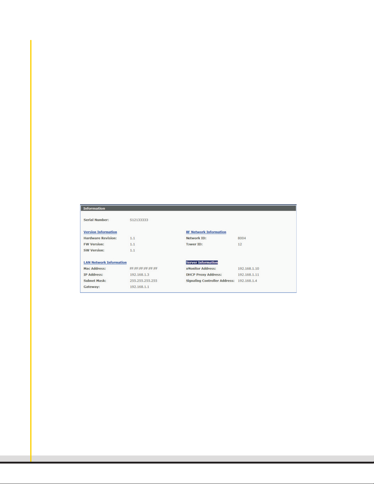
Open a Web browser program and go to https://<BME IP address>, where the BME IP address is the
address entered in Step 4 of the section Configure the Ethernet Network Interface. The BSN-250 Web
configuration interface opens to the Information screen, as shown in Figure 4.
•
Speed in bits per second
•
Parity
•
Number of stop bits
•
Modem control signals
•
Flow control
•
Break signal
•
End-of-line markers
•
Beep if buffer overrun
•
Echo what you type on screen
•
Define special (control) characters (such as what key to press for interrupt)
Figure 4: Web Configuration Interface - Information Screen
xG Technology Inc. Proprietary and Confidential Information
10

NOTE: If the Web configuration interface does not start, open the base station’s command line and use the ps
command to confirm that the Web server module is running. See Diagnostics and Troubleshooting
for more information.
The Information screen shows some of the base station’s fixed and configurable settings. Fixed factory settings include version and server information. Use the menu on the left side of the interface to configure
network, cable, and channel settings and to run diagnostics, view logs, and upgrade software.
Network Settings
Using the Web configuration interface menu, click Network Settings. This screen is used to enter IP
addresses and information about the xMAX network, enable field testing, and to set the time zone for
handsets (see Figure 5). After entering the appropriate values on this screen, click Apply to save settings, or
Cancel to return to the prior settings.
Figure 5: Web Configuration Interface – Network Settings Screen
xG Technology Inc. Proprietary and Confidential Information
11

BSN250 Guide
Address Configuration
In the Address Configuration section, enter the following information:
IP Address: Enter the planned IP address of the BSN-250 on the Ethernet interface. This address is static
and the format is per IETF conventions: 111.222.333.444. Consult your network administrator for the IP
address assigned to this BSN-250.
Subnet Mask: Enter the subnet mask for the Ethernet interface. Consult your network administrator for the
subnet mask assigned to the network.
Gateway IP Address: Enter the IP address of the gateway device on the backhaul metropolitan network
that provides access to other devices on the network, such as the xMSC. This address is static and the format
is per IETF conventions: 111.222.333.444. Consult your network administrator for the IP address of the
gateway.
Signaling Controller IP Address: The Signaling Controller controls SIP signaling between handsets or
other voice devices, and the VoIP core. Enter the default virtual IP address for the Signaling Controller, as
recommended by xG Technology (for example, 10.0.16.15). Consult your network administrator to confirm
the IP address of the Signaling Controller.
xMAX Configuration
In the xMAX Configuration section, enter the network and tower IDs:
Network ID: Enter the network ID allocated by xG Technology to this network.
Tower ID: Enter the tower ID allocated by local network planning to this BSN-250. Consult your local
network planner for the tower ID.
Field Test Mode
To enable field testing, select Enable Field Test Mode. This will prevent handsets from associating with the
base station.
Time Zone
To set the correct time for handsets, select the time zone of the physical site where the base station is located.
Optionally, specify that the time should be adjusted for Daylight Savings Time.
xG Technology Inc. Proprietary and Confidential Information
12

Cable Settings
The xMAX BSN-250 VoIP Base Station is a three-sector, 18-channel system. Using the Web configuration
interface menu, click RF Cable Settings to configure cable length and cable loss for each sector in order
to calibrate the TX Power correctly. This screen is shown in Figure 6. After entering the appropriate values,
click Apply to save settings, or Cancel to return to the prior settings.
Figure 6: Web Configuration Interface – Cable Settings Screen
RF Cable Length (ft): Specify the distance, in feet, from the RF connectors on the back of the BSN-250 to
the antenna.
RF Cable Loss (dB/100ft): Specify the loss factor/multiplier in the cable.
Total Cable Loss (dB): Specify the total loss in the cable. This field is automatically populated when the RF
cable length and loss have been entered.
xG Technology Inc. Proprietary and Confidential Information
13

BSN250 Guide
Channel Settings
Using the Web configuration interface menu, click RF Channel Settings to activate or to disable channels.
The screen shows each sector, the available channels, and the channel frequencies, as shown in Figure
7. You can enable up to six channels for each sector, and disable channels in order to avoid sources of
interference.
Figure 7: Web Configuration Interface – RF Channel Settings Screen
To enable a channel, click Enable.
•
To disable an active channel, click Disable.
•
In both cases, you are prompted for the number of minutes to delay before the channel will become active
or disabled.
xG Technology Inc. Proprietary and Confidential Information
14

diagnostiCs and troubleshooting
The Web configuration interface provides a Diagnostics screen that you can use to test base station
connectivity with a device in the network, such as the Signaling Controller or the xMonitor. To run a
diagnostics test:
1.
Enter a host name or IP address in the text box.
2.
Click Ping.
3.
The results are displayed in the Results area.
The command line interface can also be used to perform basic diagnostics, and troubleshooting if the Web
configuration interface does not start. The Linux commands ping and traceroute are supported, as well as
the ps command, which can be used to confirm if the Web server module is running, can receive queries,
and can send responses:
•
To confirm that the Web server module is running:
•
To confirm that the Web server module can receive queries:
•
To confirm that the Web server module can send responses:
xG Technology Inc. Proprietary and Confidential Information
15

BSN250 Guide
Viewing the base station aCtiVity log
A log of base station activity, such as update requests and errors, can be viewed using the Logs screen of
the Web configuration interface.
The screen shows the log on the base station at the time when the page was loaded.
•
•
Refresh.
Clear Log.
updating the xmax bsn-250 firmware
The firmware on the base station can be updated using the SW Upgrade screen of the Web configuration
interface.
The screen shows current firmware version information for the BSN-250. If an update is available, the screen
lists these as alternate versions.
•
Update. First, the file will be uploaded to the base station, then the update process will begin.
•
cess started, the operation cannot be canceled.
Cancel. After the upload has completed and the update pro-
Browse to select the upgrade file, then click
powering off the bsn-250
Use the following steps to turn OFF the system:
1.
will change from green to red.
Flip the back toggle switch to the OFF position.
2.
xG Technology Inc. Proprietary and Confidential Information
16

appendix: xmax bsn-250 front panel status
indiCators
Some units in the xMAX BSN-250 provide LED indicator lights. There are 12 LEDs installed on the front panel
of the control unit, two on the RF unit, and four on the power supply unit, for a total of 18 indicator LEDs.
Control Unit LEDs
The possible colors and meanings of the control unit LEDs are shown in Table 2.
Table 2: Control Unit LEDs
Front Panel Type Color Function Source
System LED
Link LED
Activity
TX1
RX1
TX2
RX2
TX3
RX3
GPS LED
Processor LED
Controller LED
(Tri-color)
LED Amber Ethernet activity Ethernet Controller
LED Green Transmitting on Sector 1 Control Unit CPU
LED Green Receiving on Sector 1 Control Unit CPU
LED Green Transmitting on Sector 2 Control Unit CPU
LED Green Receiving on Sector 2 Control Unit CPU
LED Green Transmitting on Sector 3 Control Unit CPU
LED Green Receiving on Sector 3 Control Unit CPU
(Tri-color)
(Tri-color)
(Tri-color)
Yellow Power ON Control Unit CPU
Green Normal operation
Red Fault
Green Ethernet link Ethernet Controller
Yellow
GPS searching for lock Control Unit CPU
Green GPS lock
Red
Yellow [Needed from xG]
No communication with GPS
Control Unit CPU
Green No alarm
Red
Yellow [Needed from xG] i.MX31
Alarm status report
Green No alarm
Red Alarm status report
xG Technology Inc. Proprietary and Confidential Information
17

BSN250 Guide
RF Unit LEDs
The possible colors and meanings of the RF unit LEDs are shown in Table 3.
Table 3: RF Unit LEDs
Front Panel Type Color Function Source
12VL (Linear) LED
12VS (Digital)
(Bi-color)
LED
(Bi-color)
Green ON
Red OFF
Red ON
Green OFF
RF Unit
RF Unit
Power Supply Unit LEDs
The possible colors and meanings of the power supply unit LEDs are shown in Table 4.
Table 4: Power Supply Unit LEDs
Front Panel Type Color Function Source
12VL (Linear) LED
12VS (Digital)
5V (Digital and
Linear)
3.3V (Digital) LED
(Bi-color)
LED
(Bi-color)
LED
(Tri-color)
(Bi-color)
Green ON Power Supply Unit
Red OFF
Green ON Power Supply Unit
Red OFF
Green Digital and linear outputs ON Power Supply Unit
Red Digital output OFF
Yellow Linear output OFF
None Digital and linear outputs OFF
Green ON Power Supply Unit
Red OFF
xG Technology Inc. Proprietary and Confidential Information
18

teChniCal support
For technical support, please contact xG Technology, Inc. using any of the following:
Telephone: 954 332-1138
Fax: 954 572-0397
Email: support@xgtechnology.com
CertifiCation
The xMAX BSN-250 complies with the U.S. Federal Communications Commission (FCC), Code of Federal
Regulations (CFR), Title 47 - Telecommunication, FCC Part 15 Subpart B- Class A Requirements.
A copy of the certification can be requested from xG Technology, Inc. by submitting your request in writing.
Our address is:
xG Technology, Inc.
Attn: Support
7771 W. Oakland Blvd., Suite 251
Sunrise, FL 33351
xG Technology Inc. Proprietary and Confidential Information
19
 Loading...