


Certification Exhibit
FCC ID: VEYCN3200R1
FCC Rule Part: 15.247
ACS Project: 14-2096
Manufacturer: xG Technology, Inc.
Model: CN3200
Manual
3998 FAU Blvd. Suite 310 Boca Raton, FL 33431 Tel: 561-961-5585 Fax: 561-961-5587
Dual Band Routing Modem - Quick Start Guide - G7603 - Release 0.1
Product features and specifications are subject to change without prior notice.
xG® and xMax® are registered trademarks of xG Technology, Inc.
All other trademarks used herein are property of their respective owners.
For the latest product documentation and software
updates, please refer to our Web site at
www.xGTechnology.com/support
xG Technology, Inc.
240 South Pineapple Avenue, Suite 701
Sarasota, FL 34236
(941) 953-9035
www.xGTechnology.com
Dual Band Routing Modem - Quick Start Guide - G7603 - Release 0.1
2
Table of Contents
Introduction ............................................................................................................... 5
About this Product ...................................................................................................... 5
About this Book .......................................................................................................... 5
Hardware Overview .................................................................................................... 5
Powering the CN3200 Modem .................................................................................... 6
Important Safety and Installation Notices ................................................................... 7
FCC Part 15 Requirement ............................................................................................ 7
Hazard ........................................................................................................................ 7
FCC Compliance .......................................................................................................... 7
RF Exposure ................................................................................................................ 8
Connecting the CN3200 Dual Band Routing Modem to the xMax Network ................. 9
Connecting Wireless Devices to the xMax Network .................................................. 10
Wired Internet Connectivity and Setting Up a WiFi Hotspot ...................................... 11
Wired Internet Connectivity ..................................................................................... 11
Technical Specifications ............................................................................................ 12
Warranty .................................................................................................................. 13
Limited Warranty ...................................................................................................... 13
SCOPE OF THE WARRANTY .............................................................................................................. 13
ADDITIONAL PROVISIONS OF THE WARRANTY ............................................................................... 14
OBTAINING SERVICE AND SUPPORT UNDER WARRANTY ............................................................... 15
EXCLUSIVITY OF THE WARRANTY .................................................................................................... 15
3
Dual Band Routing Modem - Quick Start Guide - G7603 - Release 0.1

THIS PAGE INTENTIONALLY LEFT BLANK
4
Dual Band Routing Modem - Quick Start Guide - G7603 - Release 0.1
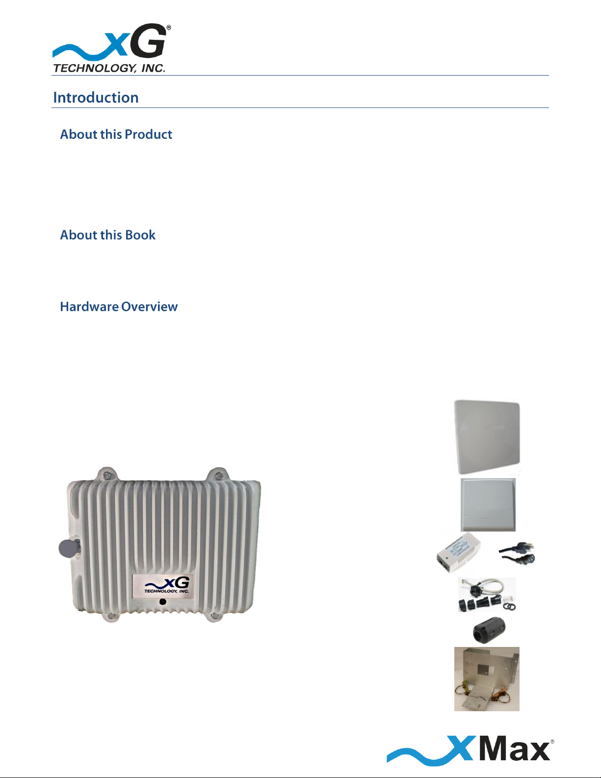
xMax Panel Antenna
and Cables (4)
2.4 GHz Panel Antenna
with Mounting Bracket
and Cable
PoE++ Power Supply
and AC Power Cord
Weatherproof
Ethernet Kit
Ferrite Beads (6)
Installation Bracket
and Hardware
The CN3200 Dual Band Routing Modem is a ruggedized subscriber device. It is waterproof and made
to handle wide temperature ranges. While primarily designed for use in fixed locations, it may also
be used in vehicular applications. It enables any Internet-ready device to connect to the xMax
network, when paired with a WiFi access point either wirelessly or through a wired Ethernet
connection.
This manual provides basic instructions for installation and configuration of the CN3200 Modem. It
also describes how to connect to the xMax Network and then connect Internet-enabled wireless
devices to the xMax Network.
The CN3200 Dual Band Routing Modem is a self-contained IEEE 802.11b/g access point which
provides any device connected to its Ethernet port access to the xMAX network. When paired with a
WiFi hotspot it provides access to the xMAX network to WiFi enabled devices. The CN3200 Modem
is totally protected against dust and moisture.
IMPORTANT: The CN3200 is professionally installed.
Dual Band Routing Modem - Quick Start Guide - G7603 - Release 0.1
5
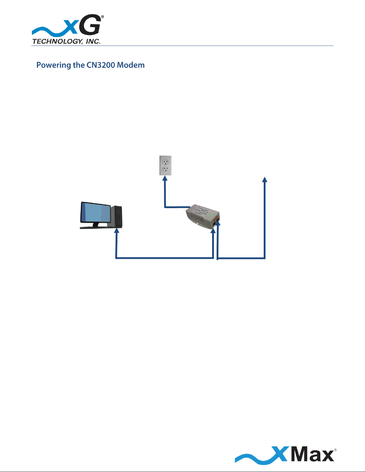
Wireless
Router
or PC
110-240
VAC,
50-60 Hz
PoE++
Power Supply
TO CN3200
Modem
ETHERNET
DATA
POWER
plus DATA
The CN3200 Modem is a Power-over-Ethernet (PoE+) device.
The IEEE 802.3at PoE+ standard enables transmission of both data and the power to
operate a device over a single Cat5/5e/6 cable connection.
The CN3200 Modem REQUIRES a PoE++ adaptor, as supplied.
The device will NOT operate with a low-power PoE switch or adaptor.
Dual Band Routing Modem - Quick Start Guide - G7603 - Release 0.1
6
ous situation, which if not avoided,
could result in death or serious injury.
These notices apply to the CN3200 Dual Band Routing Modem.
Be sure to read, understand and follow these instructions.
Heed all warnings.
Only use accessories and attachments specified by xG Technology.
Keep a copy of these instructions for future reference.
The CN1300 xMax 2.4 GHz Access Point MUST only be installed by a professional installer. It is the
responsibility of the installer to adjust the transmit power level to ensure that the output power
plus antenna gain does not cause the device to exceed FCC Part 15 output power regulations.
All antennas MUST either be located on the exterior of a vehicle or mounted on a pole.
Every antenna MUST be separated from users by more than 25 cm (0.82 ft) at all times.
NOTE
This equipment has been tested and found to comply with the limits for a Class B digital device,
pursuant to Part 15 of the FCC Rules. These limits are designed to provide reasonable protection
against harmful interference in a residential installation. This equipment generates, uses, and can
radiate radio frequency energy and, if not installed and used in accordance with the instructions,
may cause harmful interference to radio communications. However, there is no guarantee that
interference will not occur in a particular installation. If this equipment does cause harmful
interference to radio or television reception, which can be determined by turning the equipment off
and on, the user is encouraged to try to correct the interference by one or more of the following
measures:
Reorient or relocate the receiving antenna.
Increase the separation between the equipment and receiver.
Connect the equipment into an outlet on a circuit different from that to which the receiver is
connected.
Consult the dealer or an experienced radio technician for help.
Dual Band Routing Modem - Quick Start Guide - G7603 - Release 0.1
7
Changes or modifications to this device not expressly approved
by xG Technology could void the user’s authority to operate the
equipment and void the product warranty.
This equipment complies with FCC radiation exposure limits set forth for an uncontrolled
environment. This equipment should be installed and operated with minimum distance of
25 cm (0.82 ft) between the radiator and your body. This transmitter must not be co-located
or operating in conjunction with any other antenna or transmitter.
Dual Band Routing Modem - Quick Start Guide - G7603 - Release 0.1
8
IMPORTANT
Before you begin this step, it is assumed that the CN3200 Dual Band Routing Modem has been
configured as described in the CN3200 Dual Band Routing Modem Installation Guide. This was
completed by the device installer.
These steps connect the CN3200 Modem to an xMax network.
1. Connect the PoE++ Power Supply power cable to a 110 to 240 VAC power source.
2. If the CN3200 Modem is within range of an xMax Network, it connects within 2 minutes.
3. The CN3200 Dual Band Routing Modem is now fully functional.
NOTES
If the CN3200 Modem fails to connect to an xMax network after two minutes have elapsed,
ensure that the power indicator on the Power Supply is glowing GREEN.
If the CN3200 Modem is within range of an operating xMax Network, but not connecting,
follow these steps to restart the CN3200 Modem:
Power off the CN3200 Modem by disconnecting the AC cord from the Power Supply.
Wait 60 seconds.
Reconnect the AC cord to power on the CN3200 Modem.
9
Dual Band Routing Modem - Quick Start Guide - G7603 - Release 0.1
When within range of a WiFi router connected to the CN3200 Dual Band Routing Modem, any
Internet-ready device has the ability to securely connect to the Internet through the xMax Network.
These steps connect WiFi devices to the xMax Network.
1. Configure a WiFi-enabled device for Internet Protocol Version 4 (TCP/IPv4) and DHCP operation.
2. Enter the SSID and password to match that of the user-supplied WiFi router that is connected to
the CN3200. This information should have been provided by the installer.
When connected, the device can be used for any common Internet function.
10
Dual Band Routing Modem - Quick Start Guide - G7603 - Release 0.1
A properly configured device, such as a PC or laptop computer, can be wired directly to the
CN3200 Dual Band Routing Modem for Internet access.
1. Configure the device network interface for DHCP operation.
2. Using an Ethernet cable, connect the device to the CN3200 Dual Band Routing Modem.
The CN3200 Modem can be used to create a WiFi hotspot.
1. Using an Ethernet cable, connect a WiFi router to the CN3200 Modem.
2. Configure the WiFi router according to the manufacturer instructions.
11
Dual Band Routing Modem - Quick Start Guide - G7603 - Release 0.1
xMax RADIO
Tx Power Output AVG:
RANGE: 5 to 24 dBm in 1 dB steps
Receiver Sensitivity
-100 dBm BPSK / -90 dBm QAM64
2.4 GHz RADIO
Tx Power Output AVG:
8.5 to 21 dBm in 1 dB steps
Receiver Sensitivity
-93 dBm BPSK / -74 dBm QAM64
SYSTEM OVERVIEW
Frequency Band 1:
904.2 to 925.8 MHz
Channel size:
1.44 MHz
Modulation:
Adaptive BPSK / QPSK / QAM16 / QAM64
Spectral Efficiency:
Up to 4.25 Bits/Hz
PHY Protocol:
Proprietary OFDM, 2x4 MIMO
Mobility:
Up to 100 MPH
Raw Data Rate :
Up to 6 Mbps
Frequency Band 2:
2412-2462 MHz
Channel size:
20 MHz
Modulation:
Adaptive BPSK / QPSK / QAM16 / QAM64
Spectral Efficiency:
Up to 3.61 Bits/Hz
PHY Protocol:
OFDM
Mobility:
Fixed
Raw Data Rate :
Up to 72.2 Mbps
ANTENNA
Four N-type female connectors (xMax), one TNC female (2.4 GHz)
POWER
PoE++ (Power over Ethernet Plus)
PHYSICAL DESCRIPTION
Size:
8.5” x 7.5” x 3.5” (21.59 cm x 19.05 cm x 8.89 cm)
Weight:
5 lbs (2.27 kg)
ENVIRONMENTAL
Operating Temp:
-40° F to 122° F (-40° to 50° C)
Water/Dust:
IP67
Humidity:
0-100% condensing
ESD:
ESD ±30 kV
REGULATORY
EMC:
FCC CFR 47 Part 15 Class B
Vibration and Shock:
MIL-STD 810F Method 514.5 Vibration (constant acceleration),
MIL-STD 810F Method 516.5 Shock
12
Dual Band Routing Modem - Quick Start Guide - G7603 - Release 0.1
CN3200 Dual Band Routing Modem
xG Technology, Inc. (“xG”)
240 South Pineapple Avenue, Suite 701
Sarasota, FL 34236
SCOPE OF THE WARRANTY
Unless a different period is specified for a particular hardware Product, or in a sales agreement
between xG and customer, or in the published specification sheet for the hardware Product, xG's
hardware Products are generally warranted against defects in workmanship and materials for a
period of twelve (12) months from the date of original purchase, provided the Product remains
unmodified and is operated under normal and proper conditions. Unless otherwise so provided the
warranty period for computer programs in machine-readable form included in a hardware Product,
which are essential for the functionality will be coincident with the warranty period of the
hardware Product. Software patches, bug fixes or workarounds do not extend the original warranty
period. For Software sold by xG and run outside the hardware Product (e.g. xMSC), the warranty
term is 90 days from date of original purchase. All accessories (e.g. antennas, cables, power supply,
POE) carry a warranty term of 90 days from date of original purchase.
The Limited Warranty extends only to the original purchaser of the Product from xG, or its
authorized Resellers, and is not assignable or transferable to any subsequent purchaser or enduser.
xG’s warranty applies only to a Product that is manufactured by or for xG Technology and is
identified within xG’s price book at time of purchase . Any products not covered by xG’s warranty,
but supplied under the customer's Purchase Order with xG as part of the delivered equipment, are
covered under that manufacturer's standard warranty and any warranty claims should be handled
directly with that manufacturer.
xG’s warranty shall not apply: (i) to any Product subjected to accident, misuse, neglect, alteration,
acts of God, improper handling, improper transport, improper storage, improper use or application,
improper installation, improper testing or unauthorized repair; (ii) use of parts or accessories not
approved or supplied by xG, or failure to perform operator handling and scheduled maintenance
instructions supplied by xG or (iii) to cosmetic problems or defects that result from normal wear
and tear under ordinary use, and do not affect the performance or use of the Product.
If the Product develops a covered defect within the warranty period, xG will, at its option, either
repair or replace the Product found by xG to be defective or not in conformity with material
specifications, provided that the Product is returned during the warranty period.
13
Dual Band Routing Modem - Quick Start Guide - G7603 - Release 0.1

Customer is responsible for shipment to xG (or authorized service provider) and assumes all costs
and risks associated with this transportation; return shipment to the Customer will be at xG’s
expense. Customer shall be responsible for return shipment charges for Product returned where xG
determines there is no defect ("No Defect Found"), or for Product returned that xG determines is
not eligible for warranty repair. No charge will be made to customer for replacement parts for
warranty repairs.
Product that has been repaired or replaced may consist of refurbished equipment that contains
used components, some of which have been reprocessed. The used components comply with xG
Product performance and reliability specifications. The repair services provided are warranted
against defects in workmanship and materials on the repaired component of the product for a
period of 30 days from the shipment date of the repaired product, or until the end of the original
warranty period, whichever is longer.
xG is not responsible for any damage to or loss of any software programs, data or removable data
storage media, or the restoration or reinstallation of any software programs or data other than the
software, if any, installed by xG during manufacture of the Product or shipped with Product. xG’s
sole obligation for software that when properly installed and used does not substantially conform
to the published specifications in effect when the software is first shipped by xG, is to use
commercially reasonable efforts to correct any reproducible material non conformity (as
determined by xG at its sole discretion) by providing Customer with: (a) telephone or e-mail access
to report non conformance so that xG can verify reproducibility; (b) a software patch or bug-fix, if
available, or a workaround to bypass the issue, if available; and (c) where applicable, replacement
of damaged or defective external media, such as a CD-ROM disk, on which the software was
originally delivered. xG does not warrant that the use of the software will be uninterrupted, error-
free, free of security vulnerabilities, or that the software will meet Customer’s particular
requirements. Customer’s sole and exclusive remedy for breach of this warranty is, at Seller's
option, to receive (i) suitably modified software, or part thereof, or (ii) comparable replacement
software or part thereof.
ADDITIONAL PROVISIONS OF THE WARRANTY
Because it is impossible for xG to know the purposes for which the purchaser acquired this Product
or the uses to which this Product will be put, the purchaser assumes full responsibility for the
selection of the Product for its installation and use. While every reasonable effort has been made
to insure that the purchaser will receive a Product that can be used and enjoyed, xG does not
warrant that the functions of the Product will meet the purchaser’s requirements or that the
operation of the Product will be uninterrupted or error-free. xG is not responsible for problems
caused by the interaction of the Product with any other software or hardware.
14
Dual Band Routing Modem - Quick Start Guide - G7603 - Release 0.1

OBTAINING SERVICE AND SUPPORT UNDER WARRANTY
To obtain warranty service or technical support, please contact the party from whom you
purchased the product. If you purchased the product directly from xG, contact your xG Sales
Representative or call 754-206-4800. To take advantage of this Limited Warranty Purchasers are
required to supply an original point of purchase receipt. Returned Product must be accompanied by
the purchaser’s sales receipt or comparable substitute proof of sale showing the date of purchase,
the serial number of Product, and the sellers’ name and address (if purchased through a authorized
xG reseller).
EXCLUSIVITY OF THE WARRANTY
This Limited Warranty Policy shall be the sole and exclusive remedy of the purchaser with respect
to xG’s Products. xG's sole liability on any claim arising out of the sale of the Product or xG's
replacement of defective product, whether in contract, warranty, tort, or otherwise shall be limited
to the purchase price of the goods that prove defective or nonconforming. In no event shall xG be
liable for, and purchaser shall hold xG harmless from, any damages, direct, indirect, or
consequential, whether resulting from xG's negligence or otherwise, arising out of, in connection
with, or resulting from the goods sold to the Purchaser (including, without limitation, damages, for
loss of business profits, business interruption, loss of information, or any other pecuniary loss), and
any and all claims, actions, suits, and proceedings which may be instituted in respect to the
foregoing, including those made by subsequent owners and users of the goods. In no event shall xG
be liable for damages from alleged negligence, breach of warranty, strict liability, incidental or
consequential damages, or any other theory, other than the Limited Warranty set forth herein.
xG neither assumes nor authorizes any of its dealers, representatives, or any other person or entity
to assume for it any other obligation or liability beyond that which is expressly provided for in this
Limited Warranty.
xG MAKES NO WARRANTY OTHER THAN THE LIMITED WARRANTY REFERRED TO HEREIN. THIS
LIMITED WARRANTY IS EXPRESSLY IN LIEU OF ANY AND ALL OTHER EXPRESS OR IMPLIED
WARRANTIES, INCLUDING ANY IMPLIED WARRANTY OF MERCHANTABILITY OR FITNESS FOR A
PARTICULAR PURPOSE, AND IT CONSTITUTES THE ONLY WARRANTY MADE WITH RESPECT TO THE
GOODS COVERED BY THESE TERMS AND CONDITIONS. xG SHALL UNDER NO CIRCUMSTANCES BE
LIABLE FOR ANY INCIDENTAL OR CONSEQUENTIAL DAMAGES.
15
Dual Band Routing Modem - Quick Start Guide - G7603 - Release 0.1

THIS PAGE INTENTIONALLY LEFT BLANK
16
Dual Band Routing Modem - Quick Start Guide - G7603 - Release 0.1

© Copyright xG Technology, Inc. 2014. All Rights Reserved.
xG Technology, Inc.
240 South Pineapple Avenue, Suite 701
Sarasota, FL 34236
(941) 953-9035
www.xGTechnology.com
Dual Band Routing Modem - Quick Start Guide - G7603 - Release 0.1

G7604 - Release 1.0

Product features and specifications are subject to change without prior notice.
xG® and xMax® are registered trademarks of xG Technology, Inc.
All other trademarks used herein are property of their respective owners.
For the latest product documentation and software
updates, please refer to our Web site at
www.xGTechnology.com/support
xG Technology, Inc.
240 South Pineapple Avenue, Suite 701
Sarasota, FL 34236
(941) 953-9035
www.xGTechnology.com
CN3200 Dual Band Routing Modem - Installation Guide - G7604 - Release 1.0
2

Table of Contents
Introduction ............................................................................................................... 5
About this Product ...................................................................................................... 5
About this Book .......................................................................................................... 5
Before You Begin ........................................................................................................ 5
Hardware Overview .................................................................................................... 6
Powering the CN3200 Modem .................................................................................... 6
Connectors ................................................................................................................. 7
Status LED ................................................................................................................... 7
Antenna Considerations ............................................................................................. 8
Antenna Configuration ................................................................................................ 9
Important Safety and Installation Requirements ...................................................... 10
FCC Part 15 Requirement .......................................................................................... 10
Hazard ...................................................................................................................... 10
FCC Compliance ........................................................................................................ 10
RF Exposure .............................................................................................................. 11
Configuring the CN3200 Dual Band Routing Modem for the First Time ..................... 12
Installation ............................................................................................................... 15
Assemble Your Parts and Tools ................................................................................. 15
Installation Preparation ............................................................................................ 16
Installation Procedure ............................................................................................... 17
Connecting the CN3200 Dual Band Routing Modem to the xMax Network ............... 19
Connecting Wireless Devices to the xMax Network .................................................. 20
Wired Internet Connectivity and Setting Up a WiFi Hotspot ...................................... 21
Wired Internet Connectivity ..................................................................................... 21
Technical Specifications ............................................................................................ 22
Warranty .................................................................................................................. 23
Limited Warranty ...................................................................................................... 23
SCOPE OF THE WARRANTY .............................................................................................................. 23
ADDITIONAL PROVISIONS OF THE WARRANTY ............................................................................... 24
OBTAINING SERVICE AND SUPPORT UNDER WARRANTY ............................................................... 25
EXCLUSIVITY OF THE WARRANTY .................................................................................................... 25
3
CN3200 Dual Band Routing Modem - Installation Guide - G7604 - Release 1.0

THIS PAGE INTENTIONALLY LEFT BLANK
4
CN3200 Dual Band Routing Modem - Installation Guide - G7604 - Release 1.0

xMax Panel Antenna
and Cables
2.4 GHz Panel Antenna
with Mounting Bracket
and Cable
PoE++ Power Supply
and AC Power Cord
Ethernet Kit
Ferrite Beads (6)
Installation Bracket
and Hardware
The CN3200 Dual Band Routing Modem is a ruggedized subscriber device. It is waterproof and made
to handle wide temperature ranges. While primarily designed for use in fixed locations, it may also
be used in vehicular applications. It enables any Internet-ready device to connect to the xMax
network, when paired with a WiFi access point either wirelessly or through a wired Ethernet
connection.
This manual provides basic instructions for installation and configuration of the CN3200 Modem. It
also describes how to connect to the xMax Network and then connect Internet-enabled wireless
devices to the xMax Network.
IMPORTANT
The CN3200 Modem is shipped with the parts needed for basic installation and operation. These
items are shown below. Be sure each of these items is included in your product package. If any item
is missing, please contact the place of purchase.
Depending upon the requirements of your installation, you will also need to purchase additional
components such as cables and surge protectors. A checklist of typically required parts is shown in
the Assemble Your Parts and Tools section on page 15.
CN3200 Dual Band Routing Modem - Installation Guide - G7604 - Release 1.0
5

Both top Tx RF ports MUST be properly terminated
before power (PoE) is applied to the unit.
Applying power without proper RF port
termination might damage the unit
and void the product warranty.
Public
or
Private
Internet
110-240
VAC,
50-60 Hz
PoE++
Power Supply
CN3200
DATA OVER
ETHERNET
POWER
plus DATA
TERMINATE
BEFORE
POWER UP
The CN3200 Dual Band Routing Modem provides any device connected to its Ethernet port access
to the xMAX network and xMax modem. When paired with a WiFi hotspot it provides access to the
xMAX network to WiFi enabled devices. Alternately, any Ethernet capable device can access the
network via the Ethernet port. The CN3200 Modem is totally protected against dust and moisture.
The CN3200 Modem is a Power-over-Ethernet (PoE+) device.
The IEEE 802.3at PoE+ standard enables transmission of both data and the power to
operate a device over a single Cat5/5e/6 cable connection.
The CN3200 Modem REQUIRES a PoE++ adaptor, as supplied.
The device will NOT operate with a low-power PoE switch or adaptor.
CN3200 Dual Band Routing Modem - Installation Guide - G7604 - Release 1.0
6

TOP CONNECTORS
BOTTOM CONNECTORS
Tx2/Rx3
Tx1/Rx1
Rx4
Unused Port
Ethernet
Rx2
2.4 GHz ANTENNA CONNECTOR
xMax Network
GREEN
SOLID
CONNECTED
RED
SOLID
NOT
CONNECTED
STATUS LED
The CN3200 Modem features seven connectors (one is unused):
Four external xMax antenna connectors (N-type / female) on the base
A connector for an external 2.4 GHz antenna (TNC-type / female) on the top cover
A weatherproof Ethernet connector for data and PoE (Power-over-Ethernet) on the base
An unused connector
The Status LED on the CN3200 Dual Band Routing Modem indicates power, xMax Network status
and hardware fault conditions.
Under normal operating conditions, the LED glows GREEN.
CN3200 Dual Band Routing Modem - Installation Guide - G7604 - Release 1.0
7

• The CN3200 Modem is a 2x4 MIMO device with four antenna connectors
— two Tx/Rx and two Rx-only.
• All connectors are always used.
• The CN3200 Modem is mounted directly to the back of the xMax 900 MHz panel antenna
using the supplied bracket.
• If the recommended configuration is not used, CN3200 Modem should be placed as close as
possible to the antennas for optimum performance.
• The antenna cable lengths should be as short as possible.
• The installed 2.4 GHz antenna is separated from the main xMax antenna. It is mounted
within 3 feet of the main unit and oriented in the same direction as the main 900 MHz
antenna.
FOR OPTIMUM PERFORMANCE
Low-loss cables (LMR® 195/240 or equivalent) are highly recommended.
For additional information, please refer to the Antenna Configuration illustration on page 9.
8
CN3200 Dual Band Routing Modem - Installation Guide - G7604 - Release 1.0

IMPORTANT
Install the provided eight (8)
ferrite beads, as shown by this
marker in the wiring diagram.
xMax
ANTENNA
2.4 GHz
ANTENNA
110-240 VAC,
50/60 Hz
PoE++
Power
Supply
PoE
Surge
Protector
ETHERNET
DATA
POWER
plus DATA
Wireless Router or PC
PoE Surge Protector
Grounded at Building Entry
Tx/Rx Tx/Rx
Rx
Rx
This is a typical tower-mounted CN3200 Modem installation with a 2x4 MIMO Panel Antenna.
CN3200 Dual Band Routing Modem - Installation Guide - G7604 - Release 1.0
9

ous situation, which if not avoided,
could result in death or serious injury.
These notices apply to the CN3200 Dual Band Routing Modem.
Be sure to read, understand and follow these instructions.
Heed all warnings.
Only use accessories and attachments specified by xG Technology.
Keep a copy of these instructions for future reference.
The CN3200 Dual Band Routing Modem MUST only be installed by a professional installer. It is the
responsibility of the installer to adjust the transmit power level to ensure that the output power
plus antenna gain does not cause the device to exceed FCC Part 15 output power regulations.
All antennas MUST either be located on the exterior of a vehicle or mounted on a pole.
Every antenna MUST be separated from users by more than 25 cm (0.82 ft) at all times.
Shielded and grounded Ethernet cable MUST be used to avoid damage to the CN3200 Modem
unit and ensure proper operation.
Lightning Protection MUST be used on all antenna connections and Ethernet tower runs.
NOTE
This equipment has been tested and found to comply with the limits for a Class B digital device,
pursuant to Part 15 of the FCC Rules. These limits are designed to provide reasonable protection
against harmful interference in a residential installation. This equipment generates, uses, and can
radiate radio frequency energy and, if not installed and used in accordance with the instructions,
may cause harmful interference to radio communications. However, there is no guarantee that
interference will not occur in a particular installation. If this equipment does cause harmful
interference to radio or television reception, which can be determined by turning the equipment off
and on, the user is encouraged to try to correct the interference by one or more of the following
measures:
Reorient or relocate the receiving antenna.
Increase the separation between the equipment and receiver.
Connect the equipment into an outlet on a circuit different from that to which the receiver is
connected.
Consult the dealer or an experienced radio technician for help.
10
CN3200 Dual Band Routing Modem - Installation Guide - G7604 - Release 1.0

Changes or modifications to this device not expressly approved
by xG Technology could void the user’s authority to operate the
equipment and void the product warranty.
This equipment complies with FCC radiation exposure limits set forth for an uncontrolled
environment. This equipment should be installed and operated with minimum distance of
25 cm (0.82 ft) between the radiator and your body. This transmitter must not be co-located
or operating in conjunction with any other antenna or transmitter.
CN3200 Dual Band Routing Modem - Installation Guide - G7604 - Release 1.0
11

Both top Tx RF ports MUST be properly terminated
before power is applied to the unit.
Applying power without proper RF port termination
might damage the unit
and void the product warranty.
110-240 VAC,
50/60 Hz
PoE++
Power
Supply
PoE Surge
Protector
ETHERNET DATA
POWER plus DATA
GROUND
These steps set up the CN3200 Dual Band Routing Modem for use.
After completing these configuration steps, the CN3200 Modem will be fully functional and ready
for operation. It will broadcast on the configured channel. The CN3200 Modem will provide any
Internet-ready device the ability to connect wirelessly to the xMax network, using a secure
connection on a connected WiFi router.
Devices may also be connected to the xMax network through a wired Ethernet connection to the
CN3200 Modem.
For more information, see Wired Internet Connectivity and Setting Up a WiFi Hotspot on page 21.
NOTES
This procedure should be completed before installing the CN3200 Modem in a service location.
The setup sequence assumes that the CN3200 Modem device is in factory-default configuration
and has not been previously configured.
IMPORTANT: BEFORE YOU CONTINUE
Antennas or dummy loads MUST be connected to the two top Tx RF ports.
The CN3200 Dual Band Routing Modem is powered through the Ethernet cable. PoE (Power-overEthernet) is a standardized system which passes electrical power along with data on Ethernet
cabling.
After terminating the Tx RF ports, connect the provided PoE++ Power Supply as shown:
DO NOT plug the power cord into the AC outlet until directed.
CN3200 Dual Band Routing Modem - Installation Guide - G7604 - Release 1.0
12

Computer Network Adapter Settings
IP Address:
169.254.90.100
Subnet Mask:
255. 255. 255.0
CN3200 Modem Management
IP Address:
http:// 169.254.90.101
User name:
admin Password:
admin
The password is case sensitive.
1. Use a laptop or desktop computer to configure the CN3200 Modem.
Configure the computer network adapter to Internet Protocol Version 4 (TCP/IPv4)
for a static IP address and subnet mask.
BEFORE YOU CONTINUE
Be sure to take note of the current settings to restore them after configuration.
2. Using an Ethernet cable, connect the computer to the Ethernet connector on the CN3200 Modem.
3. Connect the power cable on the PoE++ Power Supply to a 110 to 240 VAC power source.
The Status LED glows RED within fifteen seconds after the power source is switched on.
NOTE
The CN3200 Modem startup process takes approximately two minutes.
Before continuing, wait until this process completes and the LED glows GREEN.
4. On the computer, open a Web browser.
5. In the browser address line, enter the IP address to open the CN3200 Modem management
window:
6. In the User name and Password fields enter:
The CN3200 Modem management window opens to the Status page.
7. The menu bar is at the top of the window. On the left side of the menu bar, click WiFi
and then, in the Wireless Settings section, update the security settings.
xG Technology strongly recommends that you change the SSID and WPA security key.
CN3200 Dual Band Routing Modem - Installation Guide - G7604 - Release 1.0
13

SSID:
Security Key:
New Password:
NOTE
Before clicking Save Changes, be sure to write down the new settings, and then keep them
in a safe place for future reference:
8. In the Wireless Settings area, enter a unique SSID for the device.
9. Select a security protocol:
1. Click the down arrow next to Security to display a drop down menu.
2. Click the desired security protocol. The best and most secure level of security is WPA2.
3. Enter the desired security key/passphrase in the Shared Key field.
4. After confirming that the settings are written down, click Save Changes.
xG Technology strongly recommends that you change the User Password.
10. To change the User Password, on the right side of the menu bar, click Admin.
NOTES
The Password is case sensitive.
Before pressing Enter, be sure to write down the new password for future reference:
Enter the User Password, and then click Enter.
The message User password was successfully updated is displayed.
11. At the bottom of the page, click Save Changes, and then on the right side of the menu bar,
click Logout to complete the configuration process.
12. Restore the network adapter to its previous settings.
CN3200 Dual Band Routing Modem - Installation Guide - G7604 - Release 1.0
14

CN3200 Dual Band Routing Modem
SUPPLIED BY xG Technology
OBTAIN FROM YOUR PART SUPPLIER
CN3200 Modem
with Wall Mount Bracket
Ethernet Cable (Length as required)
Weatherproof Ethernet Kit
Grounded PoE Surge Protector
(CTC Union SP-POE-01 or equivalent)
PoE++ Power Supply
900 MHz Panel Antenna
with mounting bracket and
4 Cables (N-Female)
2.4 GHz Panel Antenna
and Cable (TNC-Male)
Ferrite Beads
Alternative mounting solution
(as ordered)
This checklist may assist you in assembling the parts needed to complete the installation.
CN3200 Dual Band Routing Modem - Installation Guide - G7604 - Release 1.0
15

B
A C D D C B A
Locate the supplied CN3200 Modem mounting bracket and secure the CN3200 Modem to the
bracket with 4 hex-head screws, as shown.
Align the bracket onto the threaded posts on the back of the xMax Panel Antenna and then
secure it with 4 hex-nuts, as shown.
Using the wiring diagram in the Antenna Configuration section on page 9, secure the four
supplied Ethernet cables to the antenna connectors and the CN3200 Modem connectors.
IMPORTANT:
Ensure that the correct CN3200 connector is attached to the correct antenna connector.
These steps outline the basic tasks required to complete a successful installation.
Your specific steps will depend upon the requirements of your system design.
These initial steps prepare the CN3200 Dual Band Routing Modem for placement in a service
location.
CN3200 Dual Band Routing Modem - Installation Guide - G7604 - Release 1.0
16

1. Select an appropriate location and, using the supplied U-bolt mounting bracket, lightly secure
the CN3200 Modem/xMax Antenna assembly to the antenna mast.
2. Orient the antenna towards the xMax Network station and then securely tighten the nuts on the
U-bolt.
3. Using the supplied bracket and hardware, lightly secure the 2.4 GHz Panel Antenna to the
antenna mast.
4. Orient the antenna towards the xMax Network station and then securely tighten the nuts on the
U-bolt.
5. Secure the supplied coaxial cable to the connectors on the 2.4 GHz antenna and the CN3200
Modem.
6. Run Ethernet cable from the indoor CN3200 Modem PoE power supply location to the CN3200
Modem/Antennas location.
IMPORTANT
To ensure proper operation:
The maximum length of this cable run MUST be less than 100 M (109 yds.)
Outdoor-rated foil-shielded Ethernet cable MUST be used.
7. Attach two supplied ferrite cores to the CN3200 Modem end of the Ethernet cable, as shown in
the wiring diagram.
8. Attach the supplied weatherproof Ethernet connector to the Ethernet cable.
9. Secure the Ethernet cable to the connector on the mounted CN3200 Modem.
Complete the remainder of the installation at the indoor xMax Mobile Control Center location.
10. At the customer end of the Ethernet cable run, install a PoE Surge Protector at the location
where the cable enters the building.
IMPORTANT
The PoE Surge Protector MUST be properly grounded.
11. Attach two ferrite cores to the PoE Surge Protector end of the Ethernet cable, as shown in the
wiring diagram.
12. Secure the Ethernet cable to the grounded PoE Surge Protector.
17
CN3200 Dual Band Routing Modem - Installation Guide - G7604 - Release 1.0

13. Install the supplied PoE++ Power Supply near the PoE Surge Protector.
14. Using a short Ethernet cable, connect the PoE Surge Protector to the
Power plus Data (OUT) port on the PoE++ Power Supply.
15. Connect the Ethernet cable from the customer premises to the Data (IN) port on the
PoE++ Power Supply.
16. Attach two ferrite cores to the PoE Surge Protector end of the Ethernet cable, as shown in the
wiring diagram.
17. Attach two ferrite cores to the device end of the Ethernet cable.
18. Connect the Ethernet cable to the end user device (Wireless Access Point, Ethernet Switch, or
PC).
19. Connect the supplied AC Power Cord to the PoE++ Power Supply and plug it into
a 110 VAC power source.
20. If the CN3200 Modem is within range of an xMax Network, it connects within 2 minutes.
The CN3200 Dual Band Routing Modem is now fully functional.
18
CN3200 Dual Band Routing Modem - Installation Guide - G7604 - Release 1.0

IMPORTANT
Before you begin this step, it is assumed that the CN3200 Dual Band Routing Modem has been
configured as described in the steps shown in the topic:
Configuring the CN3200 Dual Band Routing Modem for the First Time on page 12.
These steps connect the CN3200 Modem to an xMax network.
1. Connect the PoE++ Power Supply power cable to a 110 to 240 VAC power source.
2. If the CN3200 Modem is within range of an xMax Network, it connects within 2 minutes.
3. The CN3200 Dual Band Routing Modem is now fully functional.
NOTES
If the CN3200 Modem fails to connect to an xMax network after two minutes have elapsed,
ensure that the power indicator on the Power Supply is glowing GREEN.
If the CN3200 Modem is within range of an operating xMax Network, but not connecting,
follow these steps to restart the CN3200 Modem:
Power off the CN3200 Modem by disconnecting the AC cord from the Power Supply.
Wait 60 seconds.
Reconnect the AC cord to power on the CN3200 Modem.
19
CN3200 Dual Band Routing Modem - Installation Guide - G7604 - Release 1.0

When within range of a WiFi router connected to the CN3200 Dual Band Routing Modem, any
Internet-ready device has the ability to securely connect to the Internet through the xMax Network.
These steps connect WiFi devices to the xMax Network.
1. Configure a WiFi-enabled device for Internet Protocol Version 4 (TCP/IPv4) and DHCP operation.
2. Enter the SSID and password to match that of the user-supplied WiFi router that is connected to
the CN3200.
When connected, the device can be used for any common Internet function.
20
CN3200 Dual Band Routing Modem - Installation Guide - G7604 - Release 1.0

A properly configured device, such as a PC or laptop computer, can be wired directly to the
CN3200 Dual Band Routing Modem for Internet access.
1. Configure the device network interface for DHCP operation.
2. Using an Ethernet cable, connect the device to the CN3200 Dual Band Routing Modem.
The CN3200 Modem can be used to create a WiFi hotspot.
1. Using an Ethernet cable, connect a WiFi router to the CN3200 Modem.
2. Configure the WiFi router according to the manufacturer instructions.
21
CN3200 Dual Band Routing Modem - Installation Guide - G7604 - Release 1.0

xMax RADIO
Tx Power Output AVG:
RANGE: 5 to 24 dBm in 1 dB steps
Receiver Sensitivity
-100 dBm BPSK / -90 dBm QAM64
2.4 GHz RADIO
Tx Power Output AVG:
8.5 to 21 dBm in 1 dB steps
Receiver Sensitivity
-93 dBm BPSK / -74 dBm QAM64
SYSTEM OVERVIEW
Frequency Band 1:
904.2 to 925.8 MHz
Channel size:
1.44 MHz
Modulation:
Adaptive BPSK / QPSK / QAM16 / QAM64
Spectral Efficiency:
Up to 4.25 Bits/Hz
PHY Protocol:
Proprietary OFDM, 2x4 MIMO
Mobility:
Up to 100 MPH
Raw Data Rate :
Up to 6 Mbps
Frequency Band 2:
2412-2462 MHz
Channel size:
20 MHz
Modulation:
Adaptive BPSK / QPSK / QAM16 / QAM64
Spectral Efficiency:
Up to 3.61 Bits/Hz
PHY Protocol:
OFDM
Mobility:
Fixed
Raw Data Rate :
Up to 72.2 Mbps
ANTENNA
Four N-type female connectors (xMax), one TNC female (2.4 GHz)
POWER
PoE++ (Power over Ethernet Plus)
PHYSICAL DESCRIPTION
Size:
8.5” x 7.5” x 3.5” (21.59 cm x 19.05 cm x 8.89 cm)
Weight:
5 lbs (2.27 kg)
ENVIRONMENTAL
Operating Temp:
-40° F to 122° F (-40° to 50° C)
Water/Dust:
IP67
Humidity:
0-100% condensing
ESD:
ESD ±30 kV
REGULATORY
EMC:
FCC CFR 47 Part 15 Class B
Vibration and Shock:
MIL-STD 810F Method 514.5 Vibration (constant acceleration),
MIL-STD 810F Method 516.5 Shock
22
CN3200 Dual Band Routing Modem - Installation Guide - G7604 - Release 1.0

CN3200 Dual Band Routing Modem
xG Technology, Inc. (“xG”)
240 South Pineapple Avenue, Suite 701
Sarasota, FL 34236
SCOPE OF THE WARRANTY
Unless a different period is specified for a particular hardware Product, or in a sales agreement
between xG and customer, or in the published specification sheet for the hardware Product, xG's
hardware Products are generally warranted against defects in workmanship and materials for a
period of twelve (12) months from the date of original purchase, provided the Product remains
unmodified and is operated under normal and proper conditions. Unless otherwise so provided the
warranty period for computer programs in machine-readable form included in a hardware Product,
which are essential for the functionality will be coincident with the warranty period of the
hardware Product. Software patches, bug fixes or workarounds do not extend the original warranty
period. For Software sold by xG and run outside the hardware Product (e.g. xMSC), the warranty
term is 90 days from date of original purchase. All accessories (e.g. antennas, cables, power supply,
POE) carry a warranty term of 90 days from date of original purchase.
The Limited Warranty extends only to the original purchaser of the Product from xG, or its
authorized Resellers, and is not assignable or transferable to any subsequent purchaser or enduser.
xG’s warranty applies only to a Product that is manufactured by or for xG Technology and is
identified within xG’s price book at time of purchase . Any products not covered by xG’s warranty,
but supplied under the customer's Purchase Order with xG as part of the delivered equipment, are
covered under that manufacturer's standard warranty and any warranty claims should be handled
directly with that manufacturer.
xG’s warranty shall not apply: (i) to any Product subjected to accident, misuse, neglect, alteration,
acts of God, improper handling, improper transport, improper storage, improper use or application,
improper installation, improper testing or unauthorized repair; (ii) use of parts or accessories not
approved or supplied by xG, or failure to perform operator handling and scheduled maintenance
instructions supplied by xG or (iii) to cosmetic problems or defects that result from normal wear
and tear under ordinary use, and do not affect the performance or use of the Product.
If the Product develops a covered defect within the warranty period, xG will, at its option, either
repair or replace the Product found by xG to be defective or not in conformity with material
specifications, provided that the Product is returned during the warranty period.
23
CN3200 Dual Band Routing Modem - Installation Guide - G7604 - Release 1.0

Customer is responsible for shipment to xG (or authorized service provider) and assumes all costs
and risks associated with this transportation; return shipment to the Customer will be at xG’s
expense. Customer shall be responsible for return shipment charges for Product returned where xG
determines there is no defect ("No Defect Found"), or for Product returned that xG determines is
not eligible for warranty repair. No charge will be made to customer for replacement parts for
warranty repairs.
Product that has been repaired or replaced may consist of refurbished equipment that contains
used components, some of which have been reprocessed. The used components comply with xG
Product performance and reliability specifications. The repair services provided are warranted
against defects in workmanship and materials on the repaired component of the product for a
period of 30 days from the shipment date of the repaired product, or until the end of the original
warranty period, whichever is longer.
xG is not responsible for any damage to or loss of any software programs, data or removable data
storage media, or the restoration or reinstallation of any software programs or data other than the
software, if any, installed by xG during manufacture of the Product or shipped with Product. xG’s
sole obligation for software that when properly installed and used does not substantially conform
to the published specifications in effect when the software is first shipped by xG, is to use
commercially reasonable efforts to correct any reproducible material non conformity (as
determined by xG at its sole discretion) by providing Customer with: (a) telephone or e-mail access
to report non conformance so that xG can verify reproducibility; (b) a software patch or bug-fix, if
available, or a workaround to bypass the issue, if available; and (c) where applicable, replacement
of damaged or defective external media, such as a CD-ROM disk, on which the software was
originally delivered. xG does not warrant that the use of the software will be uninterrupted, error-
free, free of security vulnerabilities, or that the software will meet Customer’s particular
requirements. Customer’s sole and exclusive remedy for breach of this warranty is, at Seller's
option, to receive (i) suitably modified software, or part thereof, or (ii) comparable replacement
software or part thereof.
ADDITIONAL PROVISIONS OF THE WARRANTY
Because it is impossible for xG to know the purposes for which the purchaser acquired this Product
or the uses to which this Product will be put, the purchaser assumes full responsibility for the
selection of the Product for its installation and use. While every reasonable effort has been made
to insure that the purchaser will receive a Product that can be used and enjoyed, xG does not
warrant that the functions of the Product will meet the purchaser’s requirements or that the
operation of the Product will be uninterrupted or error-free. xG is not responsible for problems
caused by the interaction of the Product with any other software or hardware.
24
CN3200 Dual Band Routing Modem - Installation Guide - G7604 - Release 1.0

OBTAINING SERVICE AND SUPPORT UNDER WARRANTY
To obtain warranty service or technical support, please contact the party from whom you
purchased the product. If you purchased the product directly from xG, contact your xG Sales
Representative or call 754-206-4800. To take advantage of this Limited Warranty Purchasers are
required to supply an original point of purchase receipt. Returned Product must be accompanied by
the purchaser’s sales receipt or comparable substitute proof of sale showing the date of purchase,
the serial number of Product, and the sellers’ name and address (if purchased through a authorized
xG reseller).
EXCLUSIVITY OF THE WARRANTY
This Limited Warranty Policy shall be the sole and exclusive remedy of the purchaser with respect
to xG’s Products. xG's sole liability on any claim arising out of the sale of the Product or xG's
replacement of defective product, whether in contract, warranty, tort, or otherwise shall be limited
to the purchase price of the goods that prove defective or nonconforming. In no event shall xG be
liable for, and purchaser shall hold xG harmless from, any damages, direct, indirect, or
consequential, whether resulting from xG's negligence or otherwise, arising out of, in connection
with, or resulting from the goods sold to the Purchaser (including, without limitation, damages, for
loss of business profits, business interruption, loss of information, or any other pecuniary loss), and
any and all claims, actions, suits, and proceedings which may be instituted in respect to the
foregoing, including those made by subsequent owners and users of the goods. In no event shall xG
be liable for damages from alleged negligence, breach of warranty, strict liability, incidental or
consequential damages, or any other theory, other than the Limited Warranty set forth herein.
xG neither assumes nor authorizes any of its dealers, representatives, or any other person or entity
to assume for it any other obligation or liability beyond that which is expressly provided for in this
Limited Warranty.
xG MAKES NO WARRANTY OTHER THAN THE LIMITED WARRANTY REFERRED TO HEREIN. THIS
LIMITED WARRANTY IS EXPRESSLY IN LIEU OF ANY AND ALL OTHER EXPRESS OR IMPLIED
WARRANTIES, INCLUDING ANY IMPLIED WARRANTY OF MERCHANTABILITY OR FITNESS FOR A
PARTICULAR PURPOSE, AND IT CONSTITUTES THE ONLY WARRANTY MADE WITH RESPECT TO THE
GOODS COVERED BY THESE TERMS AND CONDITIONS. xG SHALL UNDER NO CIRCUMSTANCES BE
LIABLE FOR ANY INCIDENTAL OR CONSEQUENTIAL DAMAGES.
25
CN3200 Dual Band Routing Modem - Installation Guide - G7604 - Release 1.0

THIS PAGE INTENTIONALLY LEFT BLANK
26
CN3200 Dual Band Routing Modem - Installation Guide - G7604 - Release 1.0

© Copyright xG Technology, Inc. 2014. All Rights Reserved.
xG Technology, Inc.
240 South Pineapple Avenue, Suite 701
Sarasota, FL 34236
(941) 953-9035
www.xGTechnology.com
G7604 - Release 1.0
 Loading...