

Page 1

VISLINK. Vislink House, 27 Maylands Avenue, Hemel Hempstead, Hertfordshire, HP2 7DE, United Kingdom.
Telephone: +44 (0)1442 431300 ● Facsimile: +44 (0)1442 431301 ● Email: [email protected] ● Website: www.vislink.com
Company Registered in England no. 1910243 VAT registration no. 448 636 222
Registered Office: Marlborough House, Charnham Lane, Hungerford, Berkshire, RG17 0EY
Page 2

Issue: 4 Page : ii
Ref: ULTD-ASUM-7001 Copyright © 2016 Vislink plc
The information contained in this manual remains the property of Vislink and may not be
used, disclosed or reproduced in any other form whatsoever without the prior written
permission of Vislink.
Vislink reserves the right to alter the equipment and specification appertaining to the
equipment described in this manual without notification.
This document is supplied on the express terms that it is to be treated as confidential and
that it may not be copied, used or disclosed to others for any purpose except as authorized
by Vislink.
NOTE: Notes are used to convey additional information.
Caution: Cautionary notes are given where potential equipment damage could occur.
Warning: Warnings are shown where there is potential for personal danger or death. This
warning should be read and understood before attempting to carry out any work
on any equipment attached or related to the equipment in use. The danger is real
and ignoring or not understanding the warning could lead to injury, harm or
potential death.
Page 3

Issue: 4 Page : iii
Ref: ULTD-ASUM-7001 Copyright © 2016 Vislink plc
Version
Date
Modification
Firmware Version
1
26/11/2015
Initial release
2
14/12/2015
Added IP Setup and Decoder
communications recovery procedure
3
21/12/2015
Added Read Me First, Quick Start Guide
and full Menu Tree. Upgrade procedure
modified. Miscellaneous corrections.
AUTOBOOT P00016 Vt00
4
17/3/2016
General revision for new release.
Updated template to new look
manual.
Versions contained in 2016-0316_Ultradecoder
Controller software:
AUTOBOOT_P0016_V1009
HEVC decoder software:
9261update-2016-01-20_16-29-20
Page 4

Issue: 4 Page : iv
Ref: ULTD-ASUM-7001 Copyright © 2016 Vislink plc
1. Introduction .............................................................................................................. 1
2. Read Me First ............................................................................................................ 3
3. Quick Start Guide....................................................................................................... 5
3.1. Connectivity Configuration ..................................................................................................... 5
3.2. Input Configuration ................................................................................................................ 6
3.3. Output Configuration ............................................................................................................. 8
4. Specifications ............................................................................................................ 9
4.1. Physical ................................................................................................................................... 9
4.2. Inputs ...................................................................................................................................... 9
4.3. Outputs ................................................................................................................................... 9
4.4. Remote Control/Monitoring ................................................................................................... 9
4.5. Performance ......................................................................................................................... 10
4.5.1. H.265 Video Formats, Resolution & Bitrates ................................................................ 10
4.5.2. Audio ............................................................................................................................. 10
4.5.3. IP Video ......................................................................................................................... 10
5. Front Panel .............................................................................................................. 11
5.1. Buttons ................................................................................................................................. 11
5.1.1. MENU ............................................................................................................................ 11
5.1.2. ESCAPE .......................................................................................................................... 11
5.1.3. STATUS .......................................................................................................................... 11
5.1.3.1. ALARM LED ............................................................................................................ 11
5.1.3.2. POWER LED ........................................................................................................... 11
5.1.4. Navigation (˄ ˅ ˂ ˃) ...................................................................................................... 11
5.1.5. ENTER ............................................................................................................................ 11
5.2. Menu Screen ......................................................................................................................... 12
5.3. USB ........................................................................................................................................ 12
6. Rear Panel ............................................................................................................... 13
6.1. IP VIDEO ................................................................................................................................ 13
6.1.1. IP to ASI ......................................................................................................................... 13
6.2. ETHERNET CONTROL............................................................................................................. 13
6.3. ASI IN..................................................................................................................................... 13
6.4. DATA ..................................................................................................................................... 13
6.4.1. MPEG DATA ................................................................................................................... 13
6.4.2. Status Relay ................................................................................................................... 13
6.4.3. Pin Outs ......................................................................................................................... 14
6.5. USB ........................................................................................................................................ 14
6.6. ETH. 1 .................................................................................................................................... 14
6.7. ETH. 2 .................................................................................................................................... 14
6.8. ASI OUT ................................................................................................................................. 14
6.9. 3G SDI ................................................................................................................................... 14
6.10. 4K HDMI ................................................................................................................................ 15
6.11. AC Power .............................................................................................................................. 15
7. IP Setup ................................................................................................................... 17
7.1. Basic ...................................................................................................................................... 17
Page 5

Issue: 4 Page : v
Ref: ULTD-ASUM-7001 Copyright © 2016 Vislink plc
7.2. Web Browser Control ........................................................................................................... 18
7.3. IP VIDEO In ............................................................................................................................ 18
7.4. Complete Configuration ....................................................................................................... 19
8. Menu Navigation ..................................................................................................... 21
8.1. Decoder Setup ...................................................................................................................... 21
8.1.1. Video ............................................................................................................................. 21
8.1.1.1. Program Number .................................................................................................. 21
8.1.1.2. Format ................................................................................................................... 21
8.1.1.3. Restart Decoder .................................................................................................... 21
8.1.2. Audio ............................................................................................................................. 22
8.1.2.1. Audio 1..4 PID ........................................................................................................ 22
8.2. Unit Setup ............................................................................................................................. 22
8.2.1. IP Options ...................................................................................................................... 22
8.2.1.1. IP Video In ............................................................................................................. 22
8.2.1.1.1. Port..................................................................................................................... 22
8.2.1.1.2. Status ................................................................................................................. 22
8.2.1.2. IP Port Setup.......................................................................................................... 22
8.2.1.2.1. Addr.................................................................................................................... 22
8.2.1.2.2. Mask ................................................................................................................... 22
8.2.1.2.3. Gway .................................................................................................................. 22
8.2.1.2.4. Traffic ................................................................................................................. 22
8.2.2. ASI Options .................................................................................................................... 23
8.2.2.1. ASI Out .................................................................................................................. 23
8.2.2.2. ASI Out Mode ........................................................................................................ 23
8.2.3. Decoder Input ............................................................................................................... 23
8.2.3.1. Decoder Input ....................................................................................................... 23
8.3. System .................................................................................................................................. 24
8.3.2. Presets ........................................................................................................................... 25
8.3.2.1. Recall from Memory ............................................................................................. 25
8.3.2.1.1. Preset ................................................................................................................. 25
8.3.2.1.2. Name .................................................................................................................. 25
8.3.2.1.3. Recall .................................................................................................................. 25
8.3.2.2. Store to Memory ................................................................................................... 25
8.3.2.2.1. Preset ................................................................................................................. 25
8.3.2.2.2. Name .................................................................................................................. 25
8.3.2.2.3. Store ................................................................................................................... 25
8.3.2.3. USB Transfer .......................................................................................................... 25
8.3.2.3.1. Recall .................................................................................................................. 26
8.3.2.3.2. Store ................................................................................................................... 26
8.3.2.4. Restore Defaults .................................................................................................... 26
8.3.2.4.1. Restore Defaults................................................................................................. 26
8.3.2.4.2. IP Defaults .......................................................................................................... 26
8.3.3. Remote Interfaces ......................................................................................................... 26
Page 6

Issue: 4 Page : vi
Ref: ULTD-ASUM-7001 Copyright © 2016 Vislink plc
8.3.3.1. Ethernet ................................................................................................................ 26
8.3.3.1.2. IP ........................................................................................................................ 27
8.3.3.1.3. Mask ................................................................................................................... 27
8.3.3.1.4. Gway .................................................................................................................. 27
8.3.3.1.5. MAC .................................................................................................................... 27
8.3.3.2. Web Identifier ....................................................................................................... 27
8.3.3.2.1. ID ........................................................................................................................ 27
8.3.4. Service ........................................................................................................................... 27
8.3.4.1. Licences ................................................................................................................. 27
8.3.4.1.1. ESN ..................................................................................................................... 27
8.3.4.1.2. Line 1 .................................................................................................................. 27
8.3.4.1.3. Line 2 .................................................................................................................. 27
8.3.4.1.4. State ................................................................................................................... 27
8.3.4.2. Time ....................................................................................................................... 28
8.3.4.2.1. Time ................................................................................................................... 28
8.3.4.2.2. Date .................................................................................................................... 28
8.3.4.2.3. Format ................................................................................................................ 28
8.3.4.2.4. Run Hours........................................................................................................... 28
8.3.4.3. Miscellaneous ....................................................................................................... 28
8.3.4.3.1. Lamp Test ........................................................................................................... 28
8.3.4.3.2. Contrast.............................................................................................................. 28
8.3.4.3.3. Fault Test ............................................................................................................ 28
8.3.4.3.4. Reboot ................................................................................................................ 28
8.3.5. Help ............................................................................................................................... 28
8.3.5.1. Unit Version........................................................................................................... 28
8.3.5.2. Decoder Version .................................................................................................... 28
8.3.5.3. Support .................................................................................................................. 29
9. Remote Control ....................................................................................................... 31
9.1. SNMP .................................................................................................................................... 31
9.3. Web Browser ........................................................................................................................ 32
9.3.1. Overview ....................................................................................................................... 32
9.3.2. Alarm Logging................................................................................................................ 34
Appendix A Software Upgrades ................................................................................. 35
A.1. Locating the Upgrade Files and Pre-Update Information ..................................................... 35
A.2. Upgrading Unit Controller via the Front Panel USB Port ...................................................... 36
A.3. Upgrading Decoder via the Rear Panel USB ......................................................................... 36
Appendix B Decoder Communications Recovery Procedure ....................................... 37
Appendix C Maintenance & Fault Finding .................................................................. 39
Appendix D Declarations of Conformity ..................................................................... 41
D.1. EC Declaration of Conformity ............................................................................................... 41
D.2. Federal Communications Commission Statement ............................................................... 42
Appendix E Full Menu Tree ....................................................................................... 43
Page 7

Issue: 4 Page : vii
Ref: ULTD-ASUM-7001 Copyright © 2016 Vislink plc
Figure 1-1 Ultra Decoder Overview ................................................................................................ 1
Figure 3-1 Routing Tab ................................................................................................................... 6
Figure 3-2 IP Video Tab ................................................................................................................... 7
Figure 3-3 Decoder Tab .................................................................................................................. 8
Figure 5-1 Front Panel Overview .................................................................................................. 11
Figure 6-1 Rear Panel Overview ................................................................................................... 13
Figure 7-1 Basic Control Ethernet Connection Configuration ...................................................... 17
Figure 7-2 Web Browser Control Ethernet Connection Configuration ........................................ 18
Figure 7-3 IP VIDEO IN Connection Configuration ....................................................................... 18
Figure 7-4 Complete Configuration Connection Configuration ................................................... 19
Figure 9-1 Web Browser Overview............................................................................................... 32
Figure 9-2 Routing Tab Overview ................................................................................................. 33
Figure 9-3 Alarm Logging Tab Overview ....................................................................................... 34
Figure A-1 Basic Configuration ..................................................................................................... 35
Figure B-1 Web Interface Screen .................................................................................................. 38
Table 6-1 Data Out Pinouts ......................................................................................................... 14
Table 8-1 Decoder Setup Menu Overview .................................................................................. 21
Table 8-2 Unit Setup Menu Overview ......................................................................................... 22
Table 8-3 System Setup Menu Overview .................................................................................... 24
Table 9-1 Web Browser Overview Functions .............................................................................. 32
Table C-1 Maintenance Error Table ............................................................................................ 39
Page 8

Issue: 4 Page : viii
Ref: ULTD-ASUM-7001 Copyright © 2016 Vislink plc
This page is intentionally unused.
Page 9
UltraDecoder Operators Manual
Introduction
Issue: 4 1
Ref: ULTD-ASUM-7001 Copyright © 2016 Vislink plc
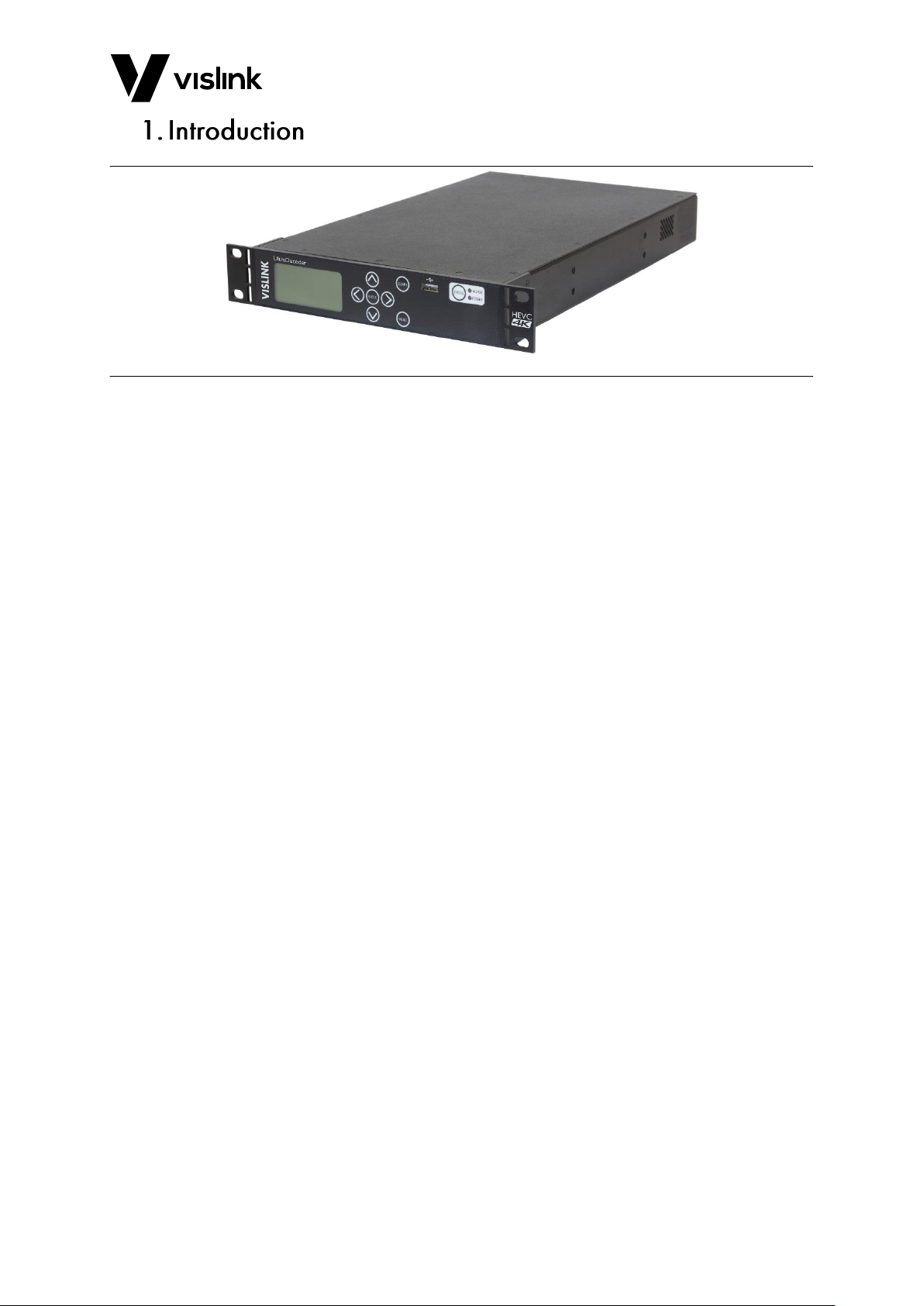
Figure 1-1 Ultra Decoder Overview
The Vislink UltraDecoder is the lightest new 1RU, half-rack width HEVC & 4K UHD capable
decoder in the world.
The system uses the latest advanced HEVC decoding techniques to offer up to 50% bit-rate
reduction compared to H.264.
In conjunction with Vislink's UltraCoder, the UltraDecoder provides a complete end to end
HEVC and 4K UHD encode and decode solution.
Full remote control is made possible using either SNMP or by the internal web server from
your preferred web browser. A clear graphical routing page in the web-browser interface
gives total control of all the possible combinations. This common control interface contains
links to the adjustable parameters for the unit.
This manual provides information on the complete range available.
NOTE: Not all options are fitted at time of manufacture. Some hardware upgrades may
require you to return the unit(s) to the factory.
NOTE: Additional licence keys, purchased to enable functions not initially ordered, may be
entered in the field.
Firmware upgrades may be offered from time to time for the customer to download into
the unit to add additional features as they become available.
Page 10

UltraDecoder Operators Manual
Introduction
Issue: 4 2
Ref: ULTD-ASUM-7001 Copyright © 2016 Vislink plc
This page is intentionally unused.
Page 11

UltraDecoder Operators Manual
Read Me First
Issue: 4 3
Ref: ULTD-ASUM-7001 Copyright © 2016 Vislink plc
The UltraDecoder is composed of two subsystems integrated within the chassis; a control
assembly and a decoder assembly. These subsystems communicate by Ethernet using the
four RJ45 connectors on the rear panel. Before the unit is powered on it is vital that these
connectors are configured in such a way that the subsystems can communicate.
To achieve a working link using the supplied cables, do either of the following:
1. Directly connect Eth. 1 to IP Video and Eth. 2 to Ethernet Control or;
2. Connect all four ports to an external Ethernet switch.
NOTE: This is shown in more detail in Chapter 7.
We recommend you use option 1. above for the initial port addresses configuration.
If the unit is to be connected to an external network, with more than one UltraDecoder
unit present, then the default IP addresses of the ports must be changed before connecting
to the external network in order to prevent IP Address clashes.
CAUTION: If an UltraDecoder is powered on without the correct network connections in
place, then the control and decoder subsystems may lose communication. If
communications are lost, follow the recovery procedure in Appendix B.
Page 12

UltraDecoder Operators Manual
Read Me First
Issue: 4 4
Ref: ULTD-ASUM-7001 Copyright © 2016 Vislink plc
This page is intentionally unused.
Page 13

UltraDecoder Operators Manual
Quick Start Guide
Issue: 4 5
Ref: ULTD-ASUM-7001 Copyright © 2016 Vislink plc
In the first instance, we recommend configuring the unit using the front panel interface
controls.
The procedure for configuring the web interface is as follows:
1. First, make the direct Ethernet connections on the rear panel using the supplied
cables, as described in Section 2.
2. If required, configure the Ethernet Control port with the appropriate IP Address,
Mask and Gateway to match your network settings. The settings for this can be
found from the front panel by selecting:
Menu | System | Remote Interfaces | Ethernet Port.
3. If you are connecting the IP Video port and Eth. 1 to your network, configure the IP
Video port by selecting:
Menu | Unit Setup | IP Options | IP Port Setup
NOTE: If you are using a direct connection, the default values can be left as is.
NOTE: If a direct connection is used between the IP Video and Eth. 1 ports then the unit
can only be used in ASI input mode.
4. Power the unit off and safely remove the supplied cables.
CAUTION: Make sure you connect the Ethernet ports to your network before reapplying
power to avoid the control and decoder subsystems loosing communication.
Access the Web Interface using the same IP address as the Ethernet Control port.
Page 14
UltraDecoder Operators Manual
Quick Start Guide
Issue: 4 6
Ref: ULTD-ASUM-7001 Copyright © 2016 Vislink plc
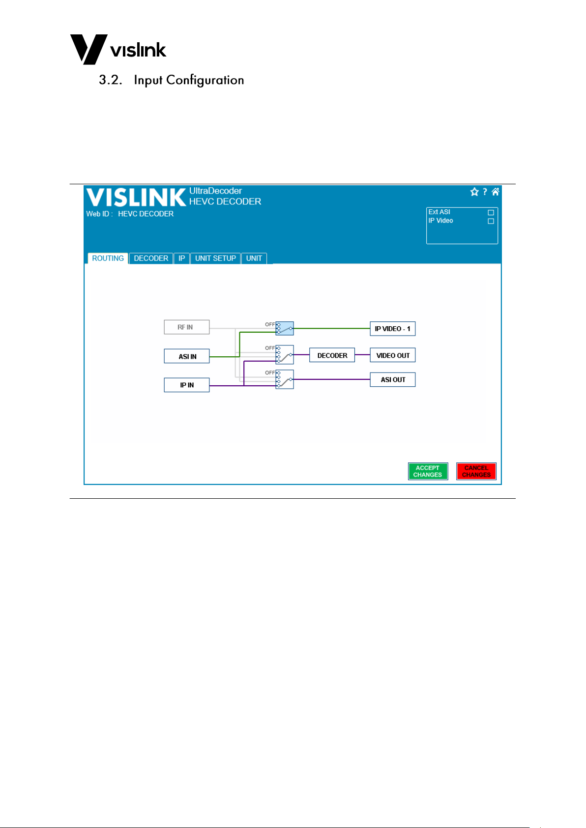
Use the switches on the routing page shown in Figure 3-1 to select the correct source
signal for the decoder. Select either the ASI input or the IP input. Press Accept Changes to
save the changes.
NOTE: Only one change can be made at a time.
If the ASI IN input is selected, then no further input configuration is required.
Figure 3-1 Routing Tab
Page 15
UltraDecoder Operators Manual
Quick Start Guide
Issue: 4 7
Ref: ULTD-ASUM-7001 Copyright © 2016 Vislink plc
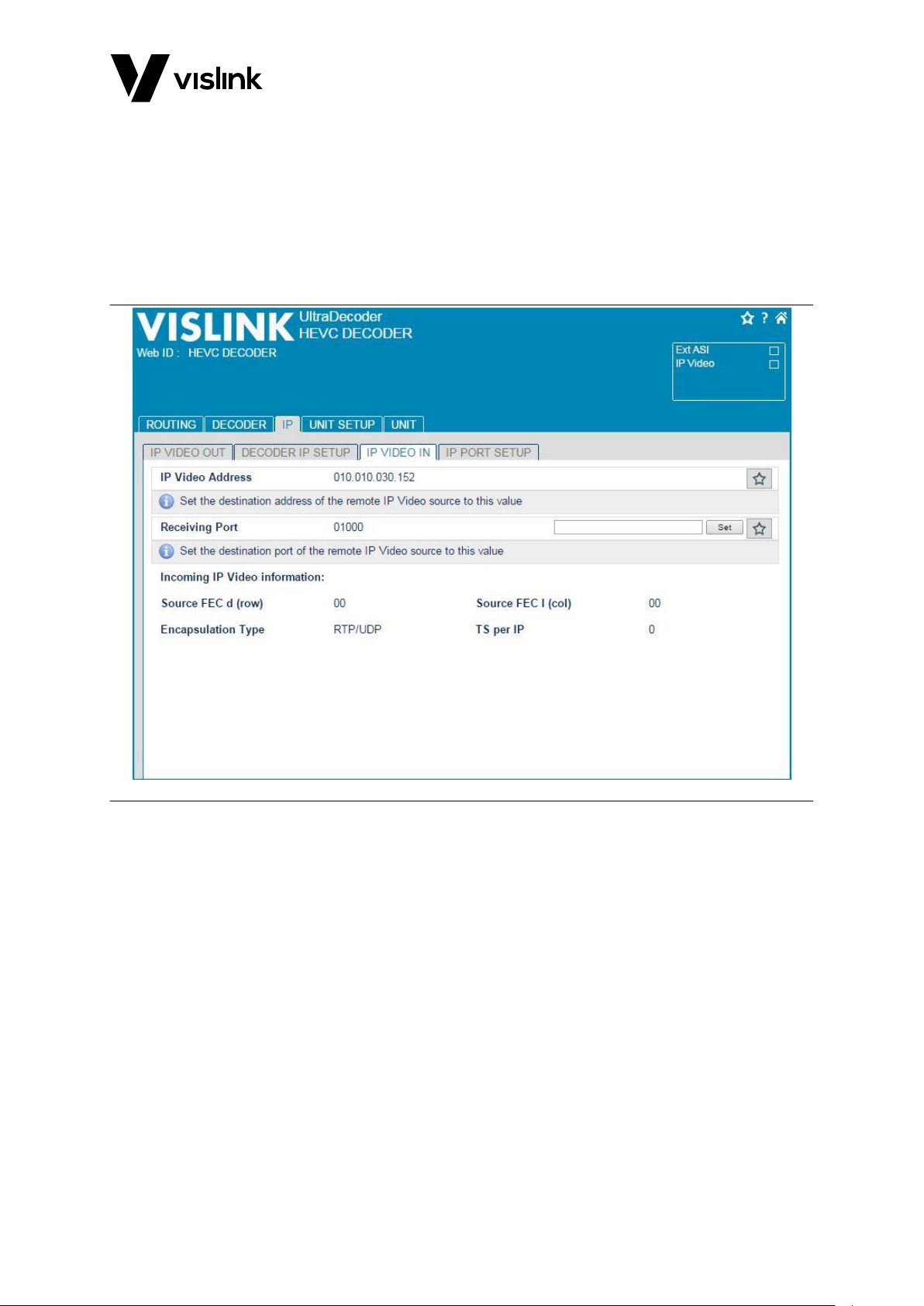
If the IP IN input is selected, it is necessary to select a receiving port number from the tab
as shown in Figure 3-2:
IP|IP Video In
The receiving address will be as configured for the IP Video port in Section 3.1. The unit
used to transmit the IP Video must be configured with matching settings.
A tick will appear in the status box top in the page header Once the system detects
incoming ASI or IP packets.
Figure 3-2 IP Video Tab
Page 16
UltraDecoder Operators Manual
Quick Start Guide
Issue: 4 8
Ref: ULTD-ASUM-7001 Copyright © 2016 Vislink plc
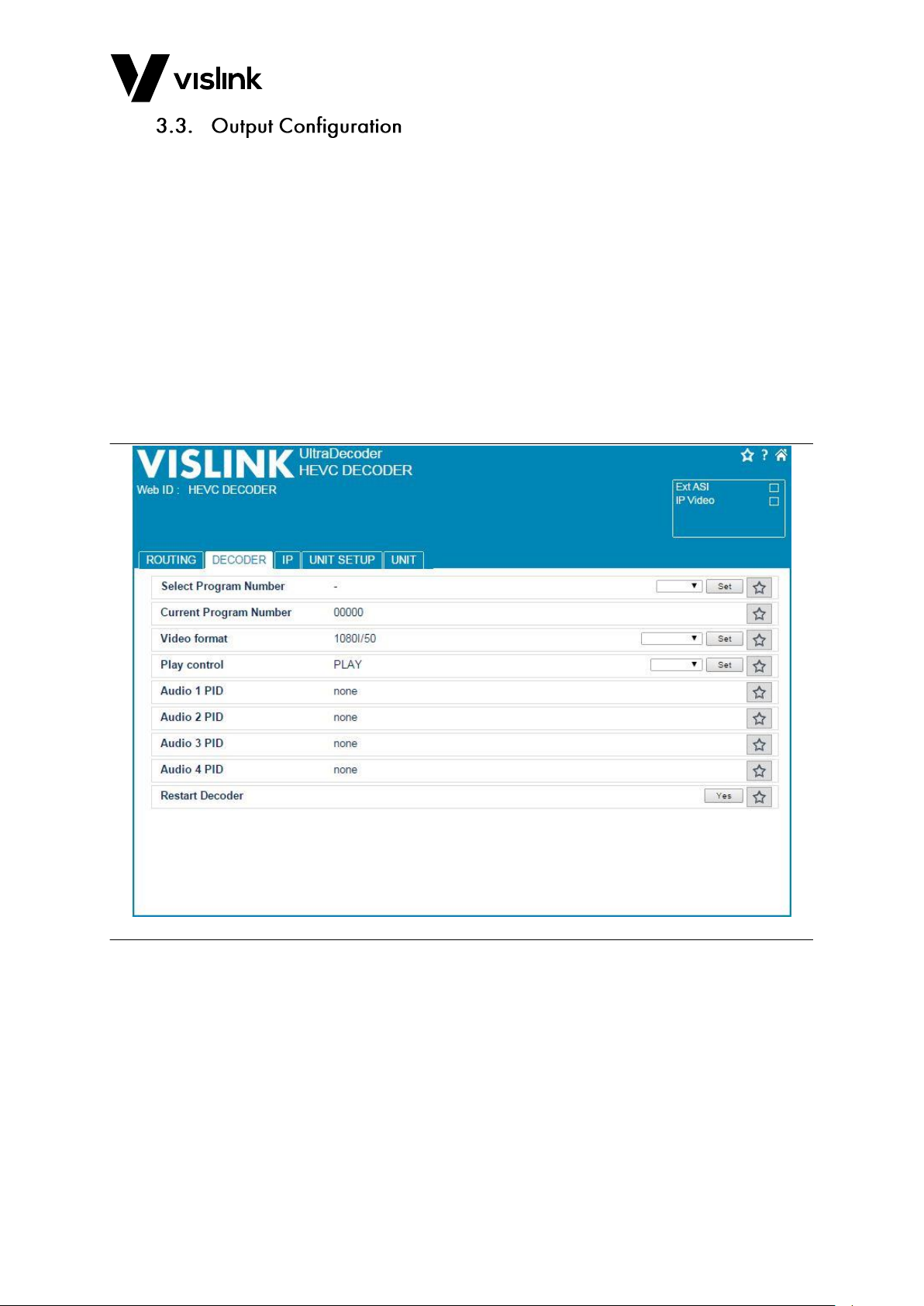
Refer to Figure 3-3 for the following output configuration:
1. If the incoming ASI stream contains more than one program, select the program
number the Select Program Number from the dropdown list in the Decoder tab.
2. Select the output format from the Video format field. The decoder will automatically
recognize the format of the incoming ASI stream and will up-scale or down-scale to
the selected format.
NOTE: It is important to select the same frame rate as the incoming ASI stream as the
decoder cannot change this.
3. Change the Play control to PLAY.
If a monitor is connected to the HDMI ports (All formats) or SDI ports (HD and SD only)
video should now display.
Figure 3-3 Decoder Tab
Page 17
UltraDecoder Operators Manual
Specifications
Issue: 4 9
Ref: ULTD-ASUM-7001 Copyright © 2016 Vislink plc
Feature
Description
Dimensions
1RU half-width chassis x 350mm deep
Weight
1.9kg approx. (4lbs)
Power Connector
3 pin IEC plug with dual fusing
AC Supply
90-264V AC 50/60Hz @ <100VA
Temperature Range
0 to +50°C operating, -20°C to +70°C storage
Humidity
90% max. non-condensing
Data
15way D-Type female
Ethernet Control & IP Video
RJ45
USB Ports
Type A
2x 3G SDI
HD BNC
ASI connections
BNC 75Ω
HDMI
1.4b (4.2.0 - 10 bit) Type A
Feature
Description
IP Video
10/100/1000 Base-T Ethernet
ASI
75Ω to ISO/IEC 13818-2 188/204Bytes constant rate
Feature
Description
ASI
75Ω to ISO/IEC 13818-2 188/204Bytes constant rate
HDMI
4K (4096 x 2160) or Ultra-HD (3840 x 2160), HD or SD (1.4b)
3G SDI
SMPTE 424M
Feature
Description
USB
For software upgrades
Remote Control
10/100Mb/s Web Browser/SNMP
IP Address (factory default)
192.168.2.6
Subnet Mask (factory default)
255.255.255.0
MAC Address
00.1D.65.nn.nn.nn (n will be unit specific)
Page 18
UltraDecoder Operators Manual
Specifications
Issue: 4 10
Ref: ULTD-ASUM-7001 Copyright © 2016 Vislink plc
Feature
Description
4K UHD Main 10
8/10 bit 4.2.0 1.0 – 40.0Mb/s
HD Main 10
8/10 bit 4.2.0 1.0 – 40.0Mb/s
SD Main
4.2.0 0.5 – 6.0Mb/s
Formats
480i @ 29.97
576i @ 25
720p @ 50, 59.94 & 60
1080i @ 50, 59.94 & 60
1080p @ 23.98, 24, 25, 29.97, 30, 50, 59.94 & 60
UHD @ 23.98, 24, 25, 29.97, 30, 50, 59.94 & 60
4K @ 23.98, 24, 25, 29.97, 30, 50, 59.94 & 60
Feature
Description
Decoder
ISO 14496-3 2006 (HE-AAC) 4 pairs
Outputs
Embedded
Feature
Description
Type
10/100/1000 Base-T Ethernet
Protocol
IEEE802.3 Ethernet
Encapsulation for ASI – RTP (RFC2250), ARP, IPv4, IGMPv2/3,
TCP/UDP
Page 19
UltraDecoder Operators Manual
Front Panel
Issue: 4 11
Ref: ULTD-ASUM-7001 Copyright © 2016 Vislink plc
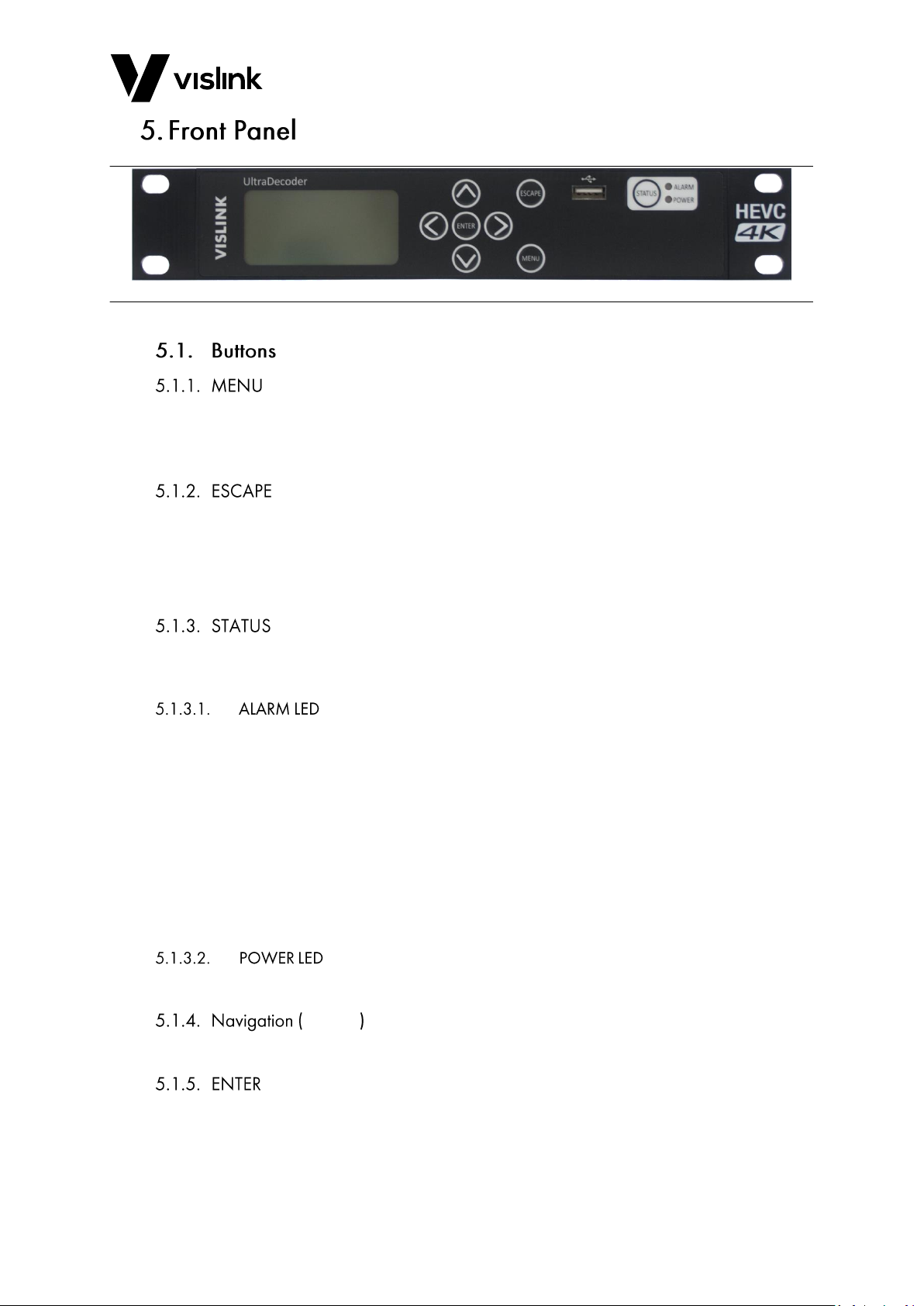
Figure 5-1 Front Panel Overview
Selecting the MENU button toggles between the menus and the AV lock status screen. It
also returns the menu screen to the main operating level from any point (as long as an
item is not being edited).
As long as an item is not being edited, selecting the ESCAPE button returns the menu
screen to the level above the current screen on display.
If an item is currently being edited, selecting the ESCAPE button cancels the change being
made and returns the item to the previously stored value.
Selecting the STATUS button toggles from the MENU screen to display the Alarm screen.
Pressing the button again returns the display to the previously displayed screen.
The Alarm LED is a tricolour LED and illuminates in different colours depending on the
alarm status:
Green shows when the system is operating as expected i.e. no alarms.
Amber shows if the system generates a warning, indicating that there is an issue you
need to be aware of.
Red shows if the system is in an error state.
Details of the errors and warnings are displayed in the Alarms screen. You can configure
which items to display as alarms and configure set their severity levels using the internal
web interface.
This LED will be illuminated green when power is applied to the unit.
˄ ˅ ˂ ˃
These buttons are used to navigate up, down, left and right around the menu screens.
This button will apply and store the selected value when editing an item.
Page 20

UltraDecoder Operators Manual
Front Panel
Issue: 4 12
Ref: ULTD-ASUM-7001 Copyright © 2016 Vislink plc
The menu screen provides the facility to configure all aspects of the unit via the front panel
buttons. See Section 8 for full details of the menu structures and functions.
This connector provides the facility to upgrade the unit’s software via a USB memory stick,
as well as downloading and uploading the unit configuration.
See Appendix A for details on upgrading the unit.
Page 21
UltraDecoder Operators Manual
Rear Panel
Issue: 4 13
Ref: ULTD-ASUM-7001 Copyright © 2016 Vislink plc
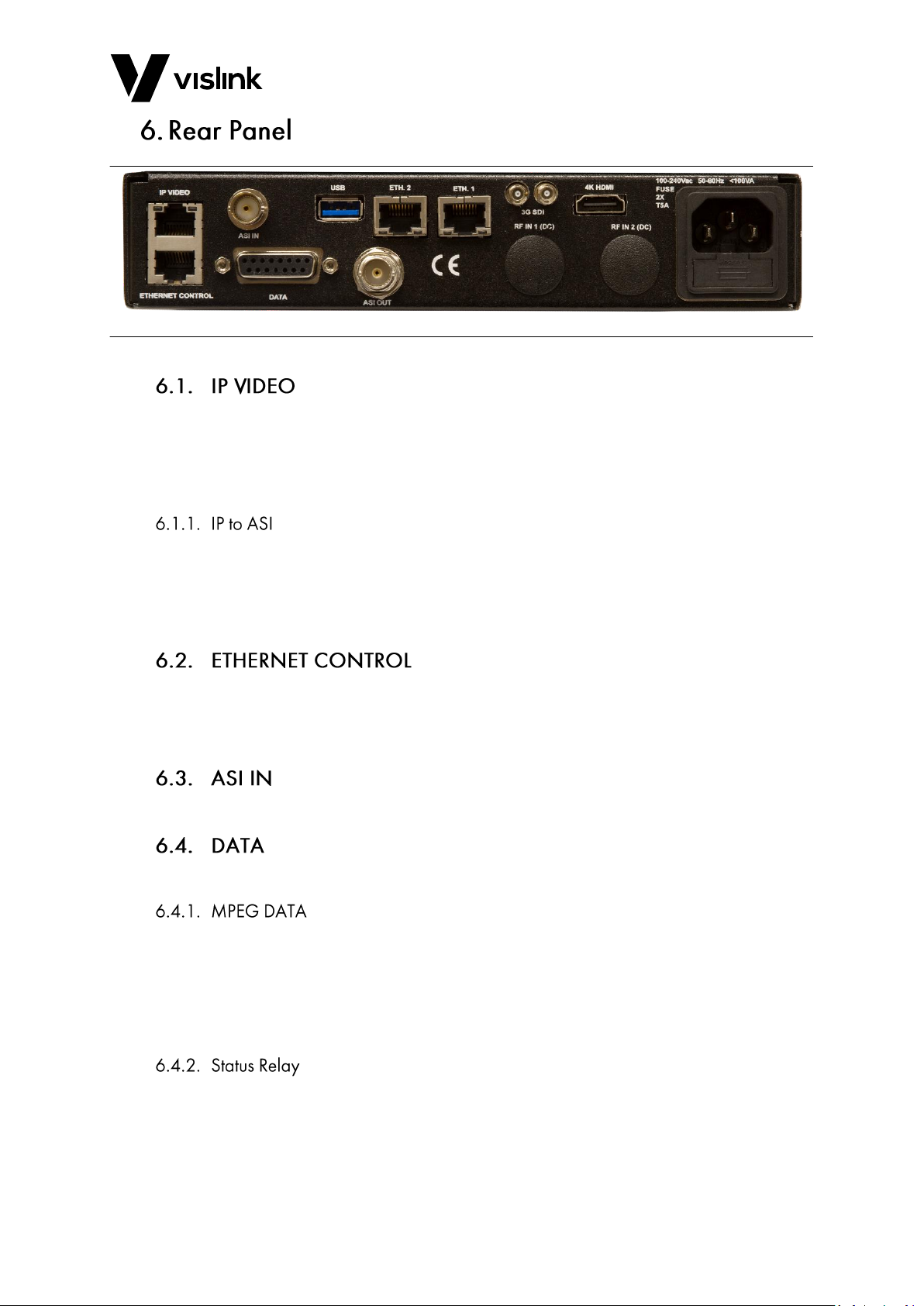
Figure 6-1 Rear Panel Overview
This connector is used for IP encapsulated ASI transport streams.
This connector must be connected to the rear panel ETH. 1 port either by the supplied
short Ethernet cable, if only ASI input mode is required or via a network switch, if IP Input
mode is required.
ASI may be de-encapsulated from an incoming RTP IP stream by selecting the appropriate
port number, as defined under the Unit Setup|IP Options|IP Video In menu.
NOTE: The external IP source must have its destination address configured to match the
value found under the IP Port Setup menu.
This connector is used to remote control the unit via SNMP or a web browser.
To ensure correct operation of the unit, an Ethernet cable must be connected to the
ETHERNET CONTROL socket with access to the ETH. 2 connection.
This 75Ω BNC is used to provide an ASI input to the decoder and/or video IP block.
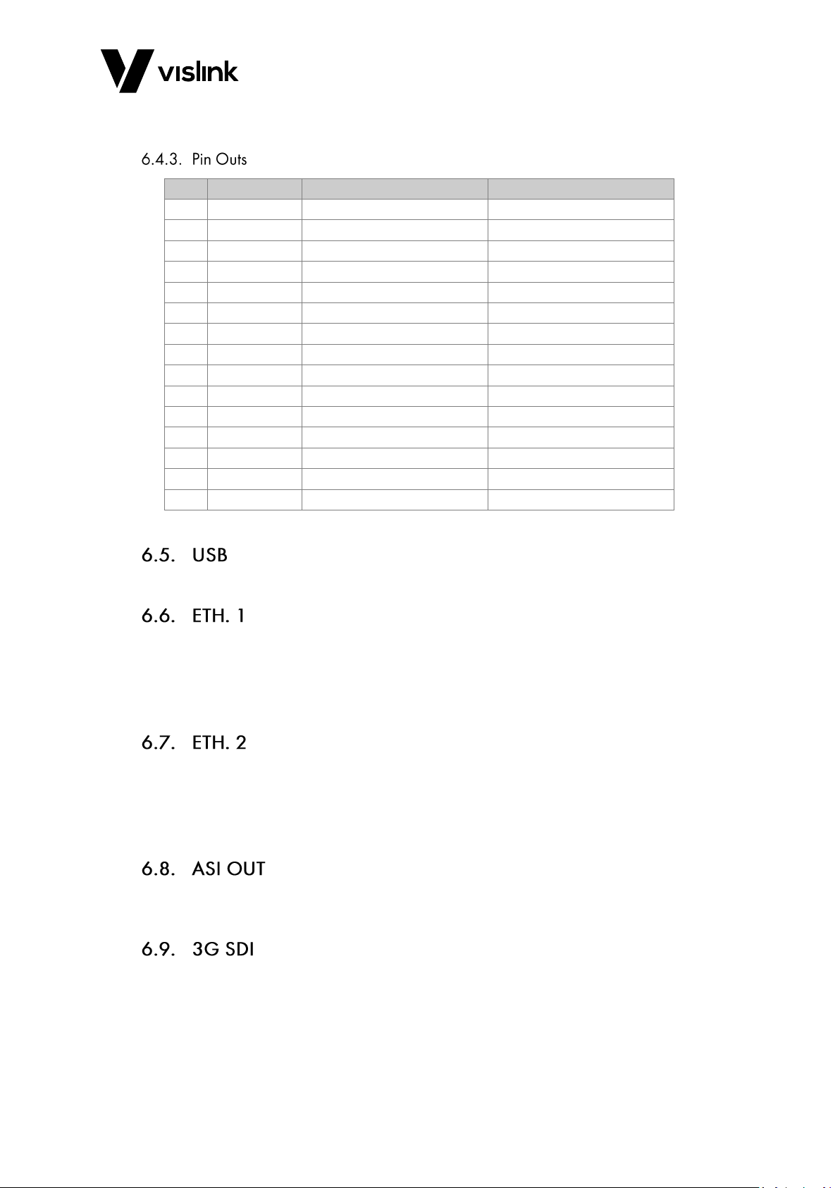
This connection is via a female 15-way D-Type connector - (Future Use).
This connection is for future use for extracting data from the MPEG stream.
MPEG data format is RS232 and the baud rates supported are:
9600, 16200, or 38400.
NOTE: TX Data to external device may not be required.
A pair of ground free relay contacts are also provided on this connector, to provide a
summary alarm status of the UltraCoder. Normally this is configured at the factory for an
open circuit indicating a fail.
This configuration may be reversed by the use of internal status link on the control PCB.
Page 22
UltraDecoder Operators Manual
Rear Panel
Issue: 4 14
Ref: ULTD-ASUM-7001 Copyright © 2016 Vislink plc
Parameters that can set the relay can be controlled via the web interface on the Alarm
Mask page, found under the Unit settings.
Pin
Signal
Description
Remark
1
NC
-
-
2
NC
-
-
3
NC
-
-
4
NC
-
-
5
NC
-
-
6
NC
-
-
7
GND - -
8
NC
-
-
9
NC
-
-
10
NC
-
-
11
NC
-
-
12
NC
-
-
13
NC
-
-
14
Status Relay
Relay contact opens on fault
Internal link to swap NC/NO
15
Status Relay
Relay contact opens on fault
Internal link to swap NC/NO
Table 6-1 Data Out Pinouts
This USB connector is used for upgrading the internal decoder.
The ETH. 1 connector is used for incoming video into the decoder section.
ETH. 1 must be connected to the rear panel IP Video port either by the supplied short
Ethernet cable (if only ASI input mode is required) or via a network switch, if IP Input mode
is required.
The ETH.2 connector is used by the control subsystem for configuring the decoder.
ETH. 2 should be connected directly to the rear panel ETHERNET CONTROL port by the
supplied short Ethernet cable or, if remote control of the UltraDecoder is required, then
the connection must be made via a network switch.
This 75Ω BNC is used to provide an ASI output, which can be derived from the ASI In signal
or ASI over IP.
These HD BNCs output the following via industry standard 3G SDI interfaces:
1080P
1080i
720P
SD
Page 23

UltraDecoder Operators Manual
Rear Panel
Issue: 4 15
Ref: ULTD-ASUM-7001 Copyright © 2016 Vislink plc
NOTE: This output is disabled when 4K or Ultra-HD are active.
The HDMI connector outputs the following to broadcast or consumer displays:
4K (4096 x 2160)
4K Ultra-HD (UHD at 3840 x 2160)
HD
SD
Power in the range of 90 – 264V AC is connected via 3 pin IEC connector. The typical total
power consumption is less than 100W.
Live and Neutral conductor fusing is employed. The two fuses integrated into the IEC
connector are ceramic, each with a T5A rating.
WARNING: Dangerous voltage are evident. Make sure you disconnect the mains power and
external IEC plug before removing any lids or covers that expose any internal
components. Not following this warning may lead to serious personal injury or
death.
Page 24

UltraDecoder Operators Manual
Rear Panel
Issue: 4 16
Ref: ULTD-ASUM-7001 Copyright © 2016 Vislink plc
This page is intentionally unused.
Page 25

UltraDecoder Operators Manual
IP Setup
Issue: 4 17
Ref: ULTD-ASUM-7001 Copyright © 2016 Vislink plc
The four Ethernet connections on the rear panel must be configured to one of the
following four variants, to ensure correct operation of the unit:
Basic (Section 7.1)
Web Browser Control (Section 7.2)
IP Video In (Section 7.3)
Complete Configuration (Section 0)
When configuring the IP addresses for the unit, the addresses for ETH. 1 and ETH. 2 are
automatically allocated based on the addresses used for the IP Video and Ethernet Control.
ETH. 1 and ETH. 2 use the same addresses plus one, as shown in the following example:
If IP Video is set to 192.168.2.6, ETH. 1 is automatically set to 192.168.0.7.
NOTE: Never assign consecutive address values to IP Video and Ethernet Control. Ensure
that the addresses plus one do not cause a conflict on any network the unit is
connected to.
If changing the default IP addresses while the unit is connected to a network, ensure that
only the decoder being configured is active. If other units are also connected, their ETH. 1
and ETH. 2 addresses are set to the values assigned on the target unit.
In this mode the unit is only configured for front panel control and may so will only receive
video via the ASI IN connector. An Ethernet cable must be connected directly between the
IP VIDEO to ETH. 1 connectors and another cable connected directly between the
ETHERNET CONTROL and ETH. 2 connectors.
Figure 7-1 Basic Control Ethernet Connection Configuration
Page 26
UltraDecoder Operators Manual
IP Setup
Issue: 4 18
Ref: ULTD-ASUM-7001 Copyright © 2016 Vislink plc
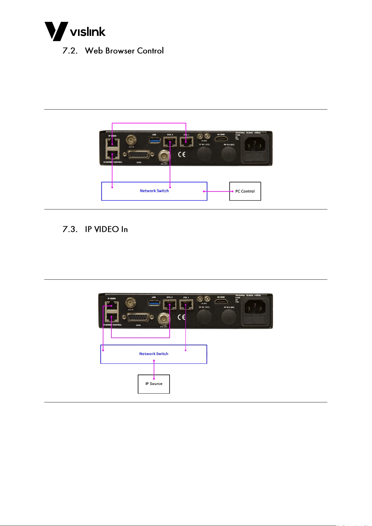
In this mode the unit is configured to receive video via the ASI IN connector only, while
allowing for configuration via a web browser. An Ethernet cable must be connected
directly between the IP VIDEO to ETH. 1 connectors, and two additional cables must be
connected between a network switch and the ETHERNET CONTROL and the ETH. 2
connectors.
Figure 7-2 Web Browser Control Ethernet Connection Configuration
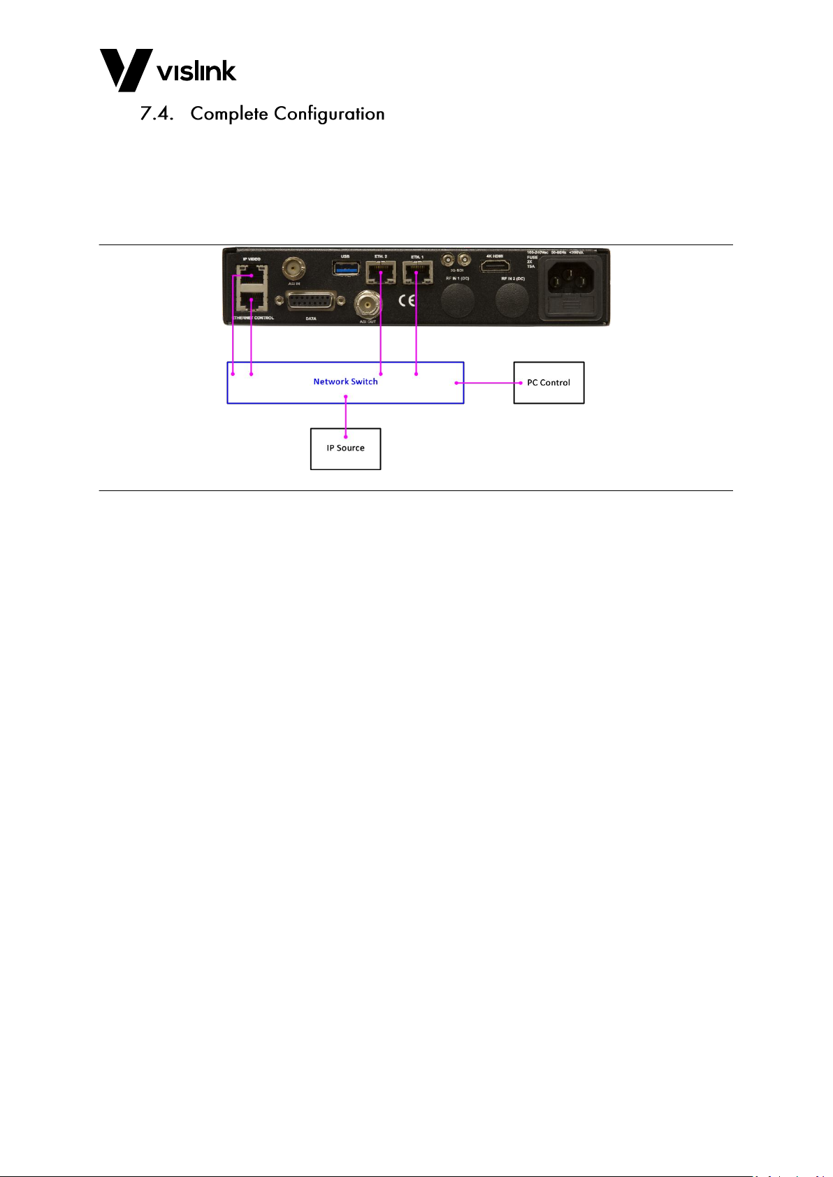
In this mode the unit is configured so that it may receive video over IP, but without remote
configuration via a web. An Ethernet cable must be connected directly between the
ETHERNET CONTROL and ETH. 2 connectors, and additional cables must be connected
between a network switch and the IP VIDEO and the ETH. 1 connectors.
Figure 7-3 IP VIDEO IN Connection Configuration
Page 27
UltraDecoder Operators Manual
IP Setup
Issue: 4 19
Ref: ULTD-ASUM-7001 Copyright © 2016 Vislink plc
In this mode the unit is configured so that it may receive video over IP and be configured
remotely via a web browser. In this instance, Ethernet cables must be connected between
a network switch and all four connectors. Different switches or VLANs can be used for the
Control and IP Video as long as the relevant ports can communicate as stated in the
previous examples, above.
Figure 7-4 Complete Configuration Connection Configuration
Page 28

UltraDecoder Operators Manual
IP Setup
Issue: 4 20
Ref: ULTD-ASUM-7001 Copyright © 2016 Vislink plc
This page is intentionally unused.
Page 29
UltraDecoder Operators Manual
Menu Navigation
Issue: 4 21
Ref: ULTD-ASUM-7001 Copyright © 2016 Vislink plc
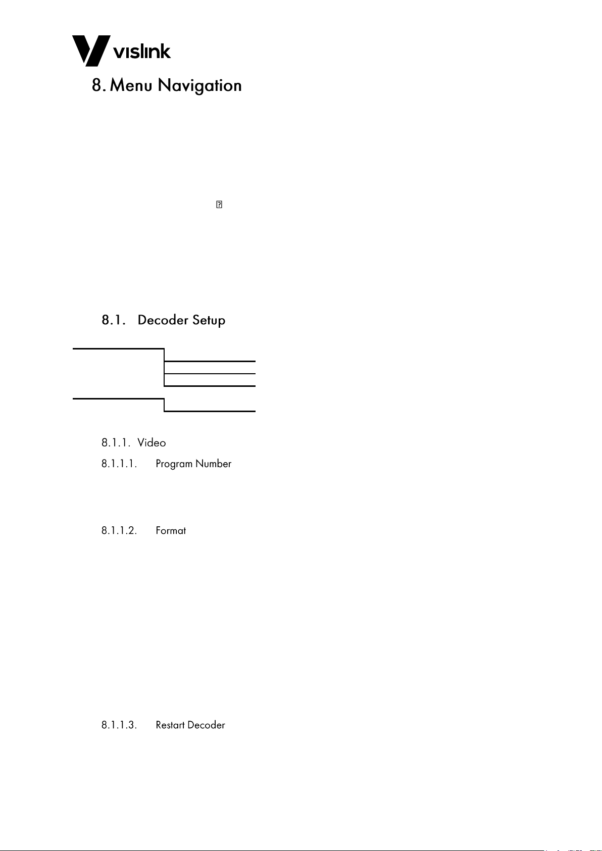
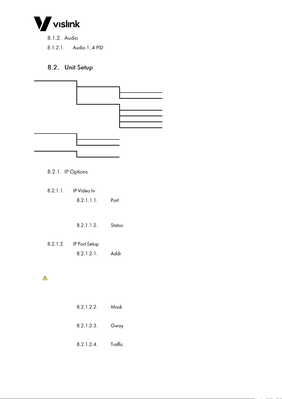
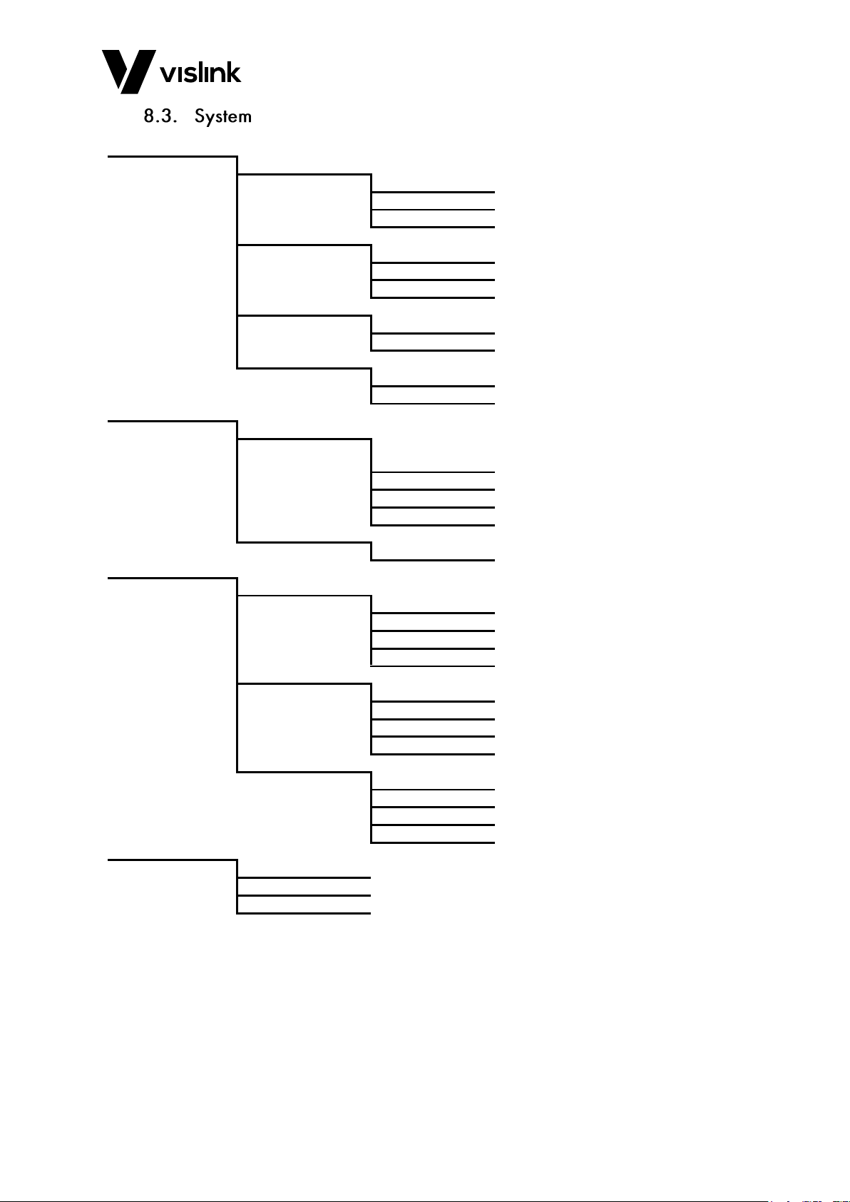
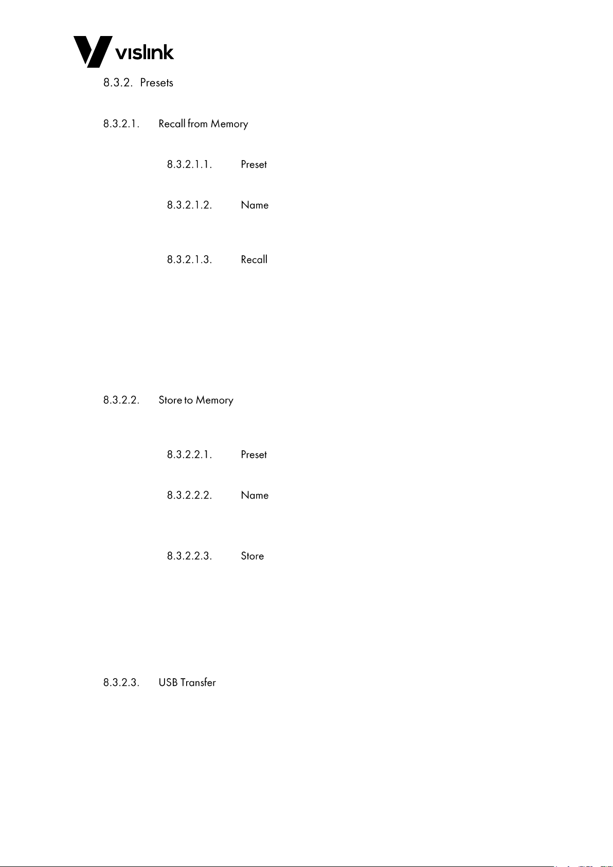
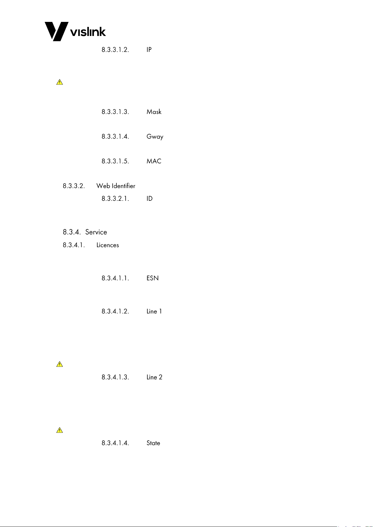
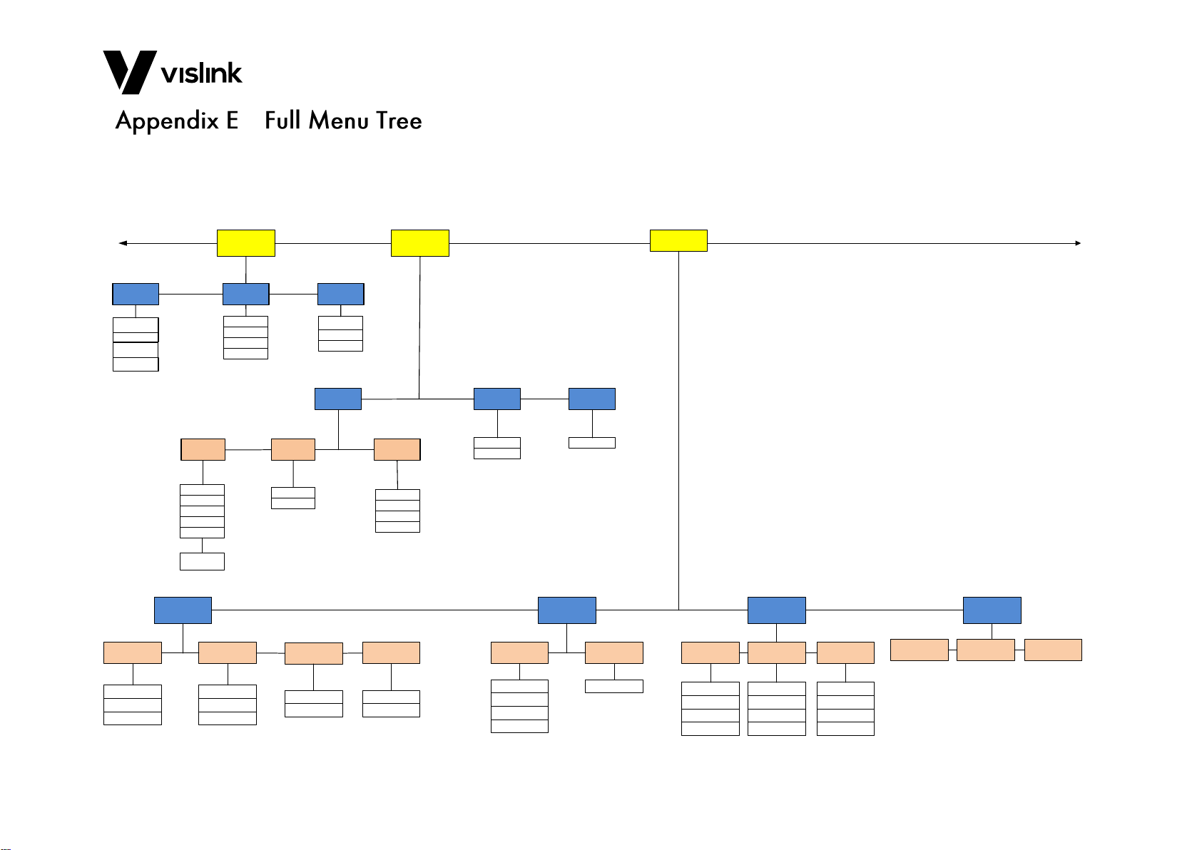
The tree views below describe the structure of the menus in the unit. Some menus
dynamically change depending on the mode of operation, therefore not all options shown
below may be available at all times. The full menu tree is shown in Appendix E.
From the main menu screen there are three options:
Decoder Setup (Section 8.1)
Unit Setup (Section 8.2)
System (Section )
The structure for each menu is shown in each section. Where a menu item is emboldened
this denotes it is an editable option. Details of each option follows.
To move through the menus, use the Navigation (˄˅˂˃) buttons to select the menu
parameter to change, followed by the ENTER button to select the next menu layer or to
edit an item. A prompt is given at the top of the screen showing the function of the
highlighted menu option.
Video
Program Number
Format
Restart Decoder
Audio
Audio 1..4 PID
Table 8-1 Decoder Setup Menu Overview
This option provides the facility to choose which service you wish to decode by selecting
the program number from a list of the current received values. The list also includes an
AUTO option which defaults the unit to always decoding the first program it receives.
This option is used to define the format of the output video. The decoder will
automatically recognise the format of the incoming ASI stream and will up-scale or
down-scale to the selected format. It is important to select the same frame rate as the
incoming ASI stream as this cannot be changed by the decoder.
Available formats are:
480i/29.97; 576i/25; 720p/50; 720p/59.94; 720p/60; 1080i/50; 1080i/59.94;
1080i/60; 1080p/23.98; 1080p/24; 1080p/25; 1080p/29.97; 1080p/30; 1080p/50;
1080p/59.94; 1080p/60; UHD/23.98; UHD/24; UHD/25; UHD/29.97; UHD/30;
UHD/50; UHD/59.94; UHD/60; 4K/23.98; 4K/24; 4K/25; 4K/29.97; 4K/30; 4K/50;
4K/59.94; and, 4K/60
UHD formats are: 2160x3840 and 4K is 2160x4096
Selecting this option will initiate a reboot of the internal decoder. To perform this action,
change the setting to YES and then press the ENTER button.
Page 30
UltraDecoder Operators Manual
Menu Navigation
Issue: 4 22
Ref: ULTD-ASUM-7001 Copyright © 2016 Vislink plc
These four options display the Audio PID being received by the decoder.
IP Options
IP Video In
Port
Status
IP Port Setup
Addr
Mask
Gway
Traffic
ASI Options
ASI Out
ASI Out Mode
Decoder Input
Decoder Input
Table 8-2 Unit Setup Menu Overview
These menus are used to configure the Video over IP settings.
This option allows you to define the listening port for receiving IP video. Valid values range
from 0 to 65535.
This option reports the status of the unit-lock for valid video over IP signals.
This item defines the IPv4 Address of the IP VIDEO connector, which will need to be
referenced by external devices when sending video over IP to the unit.
CAUTION: When modifying the Addr option value the IPv4 address for the ETH.1 connector
will automatically change to this value + 1. Before attempting to adjust the Addr
option value, ensure that ETHERNET CONTROL and ETH. 2 are connected to the
same network.
This option defines the subnet mask of the IP VIDEO connector.
This option defines the gateway of the IP VIDEO connector.
For future use.
Page 31

UltraDecoder Operators Manual
Menu Navigation
Issue: 4 23
Ref: ULTD-ASUM-7001 Copyright © 2016 Vislink plc
This menu is used to configure the source and format of the video output from the ASI O
connector on the rear panel.
This option provides the facility to define the video output from the ASI O connector.
Available settings are:
Off - no ASI output.
ASI In - ASI from the physical rear panel connector.
IP In - de-encapsulated ASI from the IP VIDEO input.
This option defines the size of the ASI packets output as either 188 or 204 Bytes.
This option allows you to define the ASI source stream, used as the decoder input.
Available settings are:
Off - no ASI output.
ASI In - ASI from the physical rear panel connector.
IP In - de-encapsulated ASI from the IP VIDEO input.
Page 32
UltraDecoder Operators Manual
Menu Navigation
Issue: 4 24
Ref: ULTD-ASUM-7001 Copyright © 2016 Vislink plc
Presets
Recall from Memory
Preset
Name
Recall
Store to Memory
Preset
Name
Store
USB Transfer
Recall
Store
Restore Defaults
Restore Defaults
IP Defaults
Remote Interfaces
Ethernet
IP
Mask
Gway
MAC
Web Identifier
ID
Service
Licences
ESN
Line 1
Line 2
State
Time
Time
Date
Format
Run Hours
Miscellaneous
Lamp Test
Contrast
Fault Test
Reboot
Help
Unit Version
Decoder Version
Support
Table 8-3 System Setup Menu Overview
Page 33
UltraDecoder Operators Manual
Menu Navigation
Issue: 4 25
Ref: ULTD-ASUM-7001 Copyright © 2016 Vislink plc
The unit contains sixteen preset configurations that can be saved and recalled.
This option provides the facility to load a previously stored configuration into the unit.
This option allows for one of the sixteen presets to be selected for recall.
This option will display the descriptive name associated with the selected Preset (if
assigned).
This option provides the facility to recall the settings associated with the selected Preset
and assign to the unit’s configuration.
To perform the recall:
1. Select this option for editing.
2. Change the value to Yes and press the ENTER button.
3. When the display changes, requesting confirmation of the action, press ENTER to
confirm or ESCAPE to cancel.
This option provides the facility to save the current unit configuration to its internal
memory.
This option allows selection of one of the sixteen presets to store the configuration to.
This option allows for a descriptive name to be assigned to the selected preset.
NOTE: The name will only be saved if the preset is saved to memory using the Store option.
This option provides the facility to store the current unit settings to the selected preset.
To perform the store:
1. Select the item for editing.
2. Change the value to Yes and press the ENTER button.
3. When the display changes, requesting confirmation of the action, press ENTER to
confirm or ESCAPE to cancel.
This option provides the facility to upload from or download presets to a USB memory
stick.
Page 34

UltraDecoder Operators Manual
Menu Navigation
Issue: 4 26
Ref: ULTD-ASUM-7001 Copyright © 2016 Vislink plc
This option provides the facility to load preset information from a previously saved file.
NOTE: Using this function will overwrite all the current presets stored in the unit (even if
the file only contains a subset of preset information).
To perform the recall:
1. First ensure that a USB memory stick is inserted into the USB connector on the front
panel with the desired configuration.txt file.
2. Select this item for editing,
3. Change the value to Yes and press the ENTER button.
4. When the display changes, requesting confirmation of the action, press ENTER to
confirm or ESCAPE to cancel.
This option provides the facility to download the unit’s configuration to a USB memory
stick.
To perform the store:
1. First ensure that a USB memory stick is inserted into the USB connector on the front
panel.
2. Select the item for editing.
3. Change the value to Yes and press the ENTER button.
4. When the display changes, requesting confirmation of the action, press ENTER to
confirm or ESCAPE to cancel.
This option provides the ability to restore the unit to its factory defaults.
To perform this action:
1. Change the setting to YES.
2. Press the ENTER button.
This option provides the ability to restore all of the unit’s IP Addresses to their factory
defaults.
To perform this action:
1. Change the setting to YES.
2. Press the ENTER button.
This section provides the facility to configure the Ethernet settings for remote control by
either SNMP or web browser.
Page 35
UltraDecoder Operators Manual
Menu Navigation
Issue: 4 27
Ref: ULTD-ASUM-7001 Copyright © 2016 Vislink plc
This option defines the IPv4 Address of the unit, used by external devices to connect to it
via SNMP or a web browser for remote configuration.
CAUTION: When modifying this option, the IPv4 address for the ETH. 2 connector
automatically change to this value + 1. Before attempting to adjust this value,
ensure that ETHERNET CONTROL and ETH. 2 are connected to the same network.
This option defines the subnet mask of the unit for remote configuration.
This option defines the gateway of the unit for remote configuration.
This option displays the MAC address of the unit.
This option allows for a descriptive text identifier to be defined. The identifier will be
displayed on the web GUI. This is useful if working with multiple units.
This option displays and allows you to input new licences. Certain features in the unit will
be unavailable, or provided with limited functionality until the relevant licence is provided.
This option displays the unit’s electronic serial number, which should be quoted when
requesting new licences.
This line displays the first fourteen characters of the unit’s licence code.
We recommend using the web GUI interface to enter a new licence using copy and paste,
however, if you need to enter a new licence code direct, it can be entered using this
option.
CATUION: Entering an incorrect licence may render the unit inoperable.
This line displays the last fourteen characters of the unit’s licence code.
We recommend using the web GUI interface to enter a new licence using copy and paste,
however, if you need to enter a new licence code direct, it can be entered using this
option.
CATUION: Entering an incorrect licence may render the unit inoperable.
This non-editable option displays whether the licence code has been accepted by the unit.
Page 36
UltraDecoder Operators Manual
Menu Navigation
Issue: 4 28
Ref: ULTD-ASUM-7001 Copyright © 2016 Vislink plc
This menu provides the facility to configure the date and time in the unit. The unit
contains an internal battery that will maintain the current time when it does not receive
external power.
This option allows for the time to be set in the unit.
This option allows for the date to be set in the unit.
This option allows for the date format to be configured to either dd/mm/yy or mm/dd/yy
(where dd represents the day, mm represents the month and yy the year).
This option displays the total amount operational of hours of the unit.
This option allows you to test the LEDs on the front panel. Each LED will cycle through its
colours, illuminating for each applicable state for the LED.
This option provides the facility to adjust the contrast of the display.
NOTE: Unlike all other options, changing this value cannot be cancelled by use of the
ESCAPE button.
This option provides the facility to perform a fault test of the unit. Any errors or warnings
reported are displayed on the Alarm page, which is accessed via the Status button.
Selecting this option reboots the unit.
To perform this action:
1. Change the setting to YES.
2. Press the ENTER button.
These menus provide information regarding the unit’s software versions, plus contact
details should you require help from our customer support. Please refer to the serial and
version numbers when contacting customer support.
This menu displays the physical serial number of the unit, the current build version of the
software and kernel version.
This menu displays the serial number and version of the internal decoder.
Page 37

UltraDecoder Operators Manual
Menu Navigation
Issue: 4 29
Ref: ULTD-ASUM-7001 Copyright © 2016 Vislink plc
This menu displays contact information for Vislink customer support in the event that it is
required.
Page 38

UltraDecoder Operators Manual
Menu Navigation
Issue: 4 30
Ref: ULTD-ASUM-7001 Copyright © 2016 Vislink plc
This page is intentionally unused.
Page 39

UltraDecoder Operators Manual
Remote Control
Issue: 4 31
Ref: ULTD-ASUM-7001 Copyright © 2016 Vislink plc
This equipment may be controlled by SNMP via a network connection to the ETHERNET
CONTROL connector on the rear panel.
The command set is defined by the MIB. To ensure the MIB is up to date, a dedicated URL
allows for the download of the MIB as a text file.
The URL is:
http://<ipaddrress>/common/DVE5151-MIB.txt (case sensitive),
NOTE: The field shown as <ipaddress> must be replaced with the actual IP address of the
unit. This information is found under the menu: System|Remote Interfaces|
Ethernet.
The MIB may also be downloaded using the unit’s web interface, from the Unit|Control
page.
Page 40
UltraDecoder Operators Manual
Remote Control
Issue: 4 32
Ref: ULTD-ASUM-7001 Copyright © 2016 Vislink plc
You can control equipment using your preferred web browser via your network through
the ETHERNET CONTROL connector on the rear panel.
Whilst every effort is made to ensure that the interface works with all web browsers, we
cannot guarantee that it will be fully compatible with old versions or exceedingly new ones.
NOTE: We recommend using either IE (minimum version 7) or Firefox (minimum version
2.0.0.11).
When the interface is first accessed from your preferred browser, features required by the
interface are checked and their status displayed.
Normally, connection to the web interface would be achieved over a network, however it is
possible to directly connect a PC to the unit. If this is required and the PC Ethernet port is
not an autosensing type, use a crossover Ethernet cable.
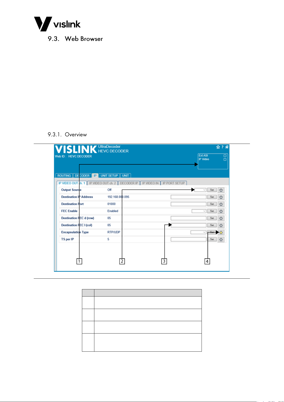
Figure 9-1 Web Browser Overview
ID
Function
1.
Status summary of unit. Top right icons for
favourites, help and Home page.
2.
Drop-down list of selectable items. Choose desired
value, then press the Set button to apply.
3.
Edit box. Type in the desired value, then press the
Set button, or select the Enter button to apply.
4.
Favourites selection. Click on this button to
illuminate it, to make it accessible from the
favourites button at the top right of the screen.
Table 9-1 Web Browser Overview Functions
Page 41
UltraDecoder Operators Manual
Remote Control
Issue: 4 33
Ref: ULTD-ASUM-7001 Copyright © 2016 Vislink plc
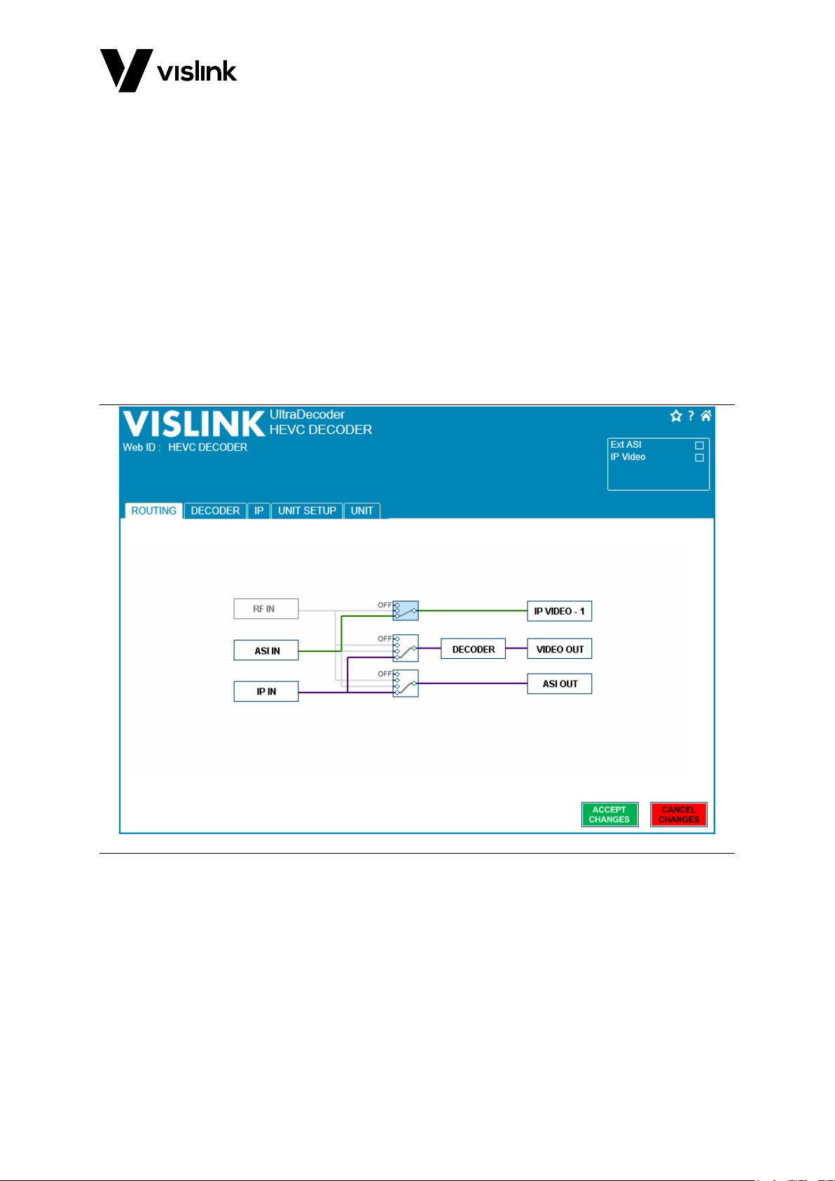
Because of the flexibility of use of the unit, an overall routing page is provided to give
access to all major adjustable items of the unit.
Grey lines show all the possible routings and coloured lines represent either the current
routing or the routing that will be used when the Accept Changes button is selected. The
Accept Changes and Cancel Changes buttons will only show if the configuration has
changed.
Clicking on the switch boxes will step through the possible routing for that switch. Clicking
on the function link boxes will automatically change the display, switching to the relevant
page to configure the selected feature.
NOTE: Only one switch may be changed at a time.
An example of the routing page is shown in Figure 9-2.
NOTE: The display will differ depending on the unit’s configuration and the licences
applied.
Figure 9-2 Routing Tab Overview
Page 42
UltraDecoder Operators Manual
Remote Control
Issue: 4 34
Ref: ULTD-ASUM-7001 Copyright © 2016 Vislink plc
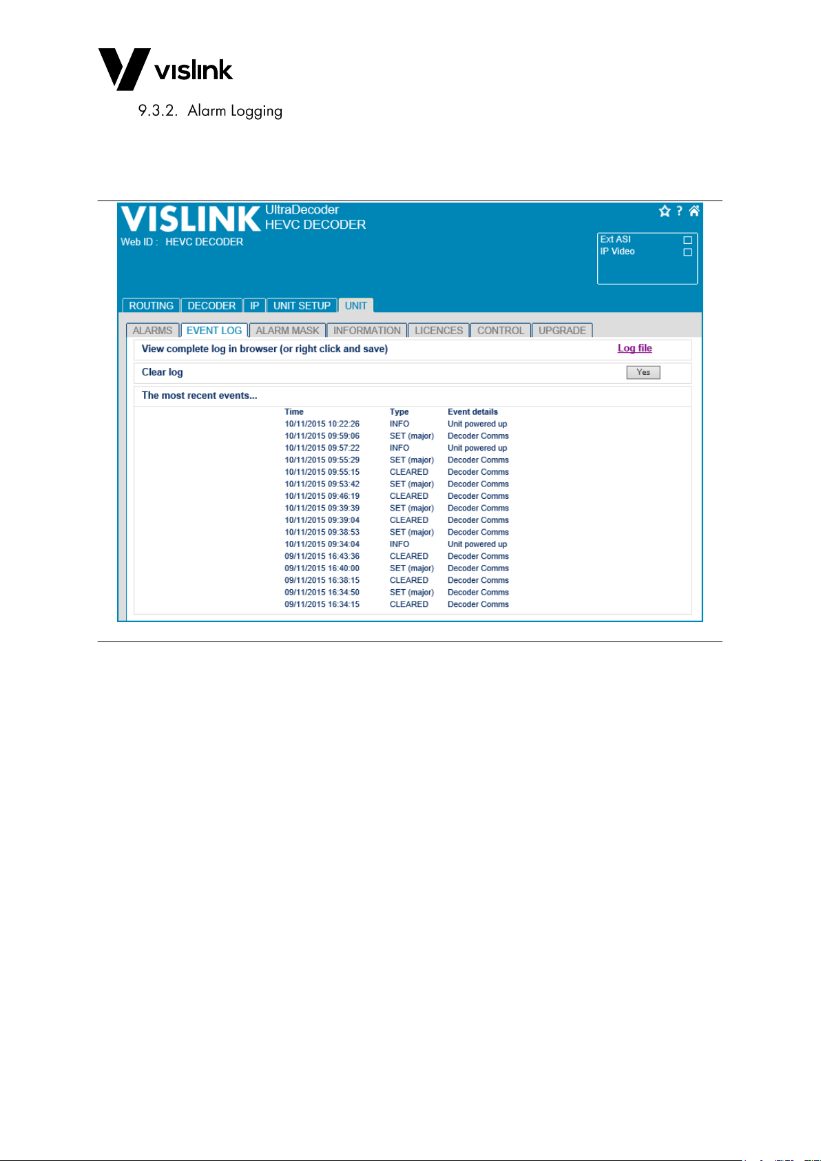
The Alarm Log tab is accessed under the Unit tab. This page shows the most recent alarm
events, the information is updated and shown in real time. Further options are provided to
clear events and to view and save the entire list of alarms.
Figure 9-3 Alarm Logging Tab Overview
Page 43
UltraDecoder Operators Manual
Remote Control
Issue: 4 35
Ref: ULTD-ASUM-7001 Copyright © 2016 Vislink plc
The UltraDecoder is composed of two subsystems integrated within the chassis namely a
control assembly and a decoder assembly.
Both assemblies should be updated in sequence, using the following procedures.
You require two formatted, blank USB sticks to complete the upgrade.
NOTE: Before attempting USB upgrades, ensure the USB stick is formatted to Fat32.
NOTE: Combined MP3 player/memory sticks are not compatible with the unit.
The assemblies use different update files:
The control assembly update is performed via the front panel USB socket and the file
is named: AUTOBOOT_P0016_xxxxx.
The decoder assembly update is performed via the rear panel USB socket and the file
is named: 9261update-xxxxx.
The upgrade files are available from our FTP site to download and transfer onto a USB
memory stick:
1. Download the above named firmware upgrade files, available from:
ftp://ftp.vislink.com/Vislink%20Products/Ultradecoder/Firmware/
2. Save the upgrade files to an easy to find location on your PC to copy later.
NOTE: Before attempting an upgrade, ensure there is only one upgrade file present on the
USB stick.
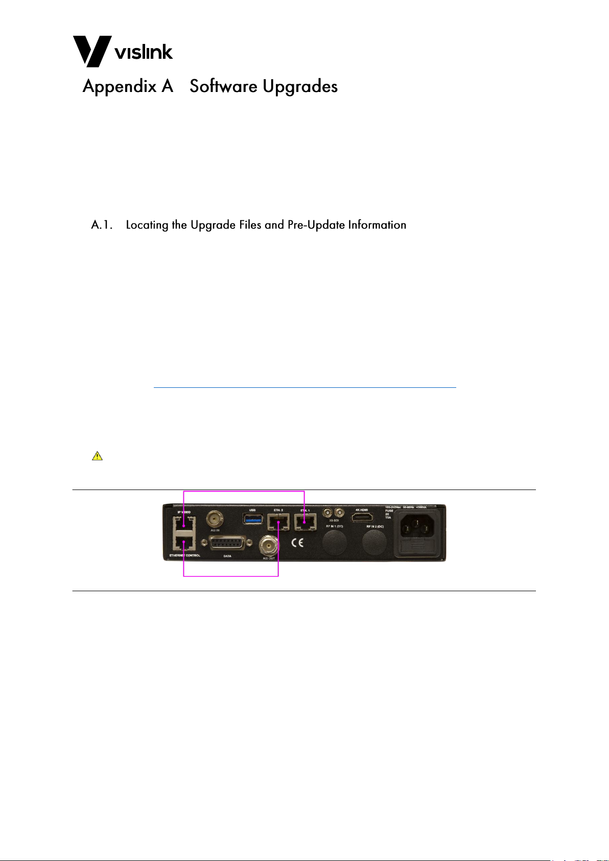
CAUTION: Ensure you use the Basic Mode configuration connections to perform the unit
upgrade, as in Figure A-1. For more information on Basic Mode (see Section 7.1).
Figure A-1 Basic Configuration
Page 44
UltraDecoder Operators Manual
Remote Control
Issue: 4 36
Ref: ULTD-ASUM-7001 Copyright © 2016 Vislink plc
1. To update the controller subassembly, copy the upgrade file named
AUTOBOOT_P0016_xxxxx to a formatted, blank USB stick.
2. Insert the USB memory stick into the unit’s front panel USB connector.
3. Power on the unit.
NOTE: If the unit is already powered on, power it down and wait five minutes before
reapplying power.
4. The front panel display should show Upgrade Started, followed by information
regarding the unit parts being upgraded.
5. On successful completion, the front panel displays Upgrade Completed Remove USB
stick and power-cycle.
In the event Upgrade failed displays, an error code will also show. The following list shows
some possible error codes:
B1 – Error upgrading unit – retry upgrade procedure
B2 – Factory upgrade only – unit software too old
A4 – Kernel version too old – contact factory
Bx – Unknown error in upgrade – retry upgrade
Ax – Boot error – contact factory for back to base upgrade
1. To update the Decoder subassembly, copy the upgrade file named 9261update-xxxxx
to a formatted, blank USB stick.
2. Ensure the UltraDecoder is not on a network with other units.
3. Power on the unit to be up-graded.
4. Once fully booted, insert the memory stick containing the upgrade file into rear USB
socket.
5. After a few seconds the alarm light (status led) turns red, after about 5 minutes this
LED returns to Green, indicating the upgrade is complete
NOTE: Note this can take up to 15 minutes.
6. Remove the USB stick.
Page 45

UltraDecoder Operators Manual
Remote Control
Issue: 4 37
Ref: ULTD-ASUM-7001 Copyright © 2016 Vislink plc
If communications to the internal decoder are lost, please perform the following steps to
remedy the fault:
1. Using the supplied cables, connect ETH. 1 to IP VIDEO port and ETH. 2 to ETHERNET
CONTROL port as per the Basic Configuration, see Section 7.1.
2. Using a blank memory stick (formatted to FAT32) copy the file named 9261reset
from:
ftp://ftp.vislink.com/Vislink Products/Ultradecoder/Recovery/
3. Power on the unit.
4. When the unit has completed its boot process, use the front panel navigation keys to
locate the System|Presets|Restore Defaults menu.
5. Set the IP Defaults option to Yes.
NOTE: After about 20 seconds the unit will restart.
6. When the unit has fully re-started, plug the memory stick in to the rear USB socket.
Wait approximately 30 seconds, the alarm light should go from red to green. When
this happens, remove the memory stick and power cycle the unit.
NOTE: Communications with the Decoder should be recovered when the unit reboots.
7. Finally, use the front panel to locate the menu System|Presets|Restore Defaults and
set the Restore Defaults option to Yes.
8. Power cycle the unit.
9. When the unit reboots, navigate to the menu Unit Setup|IP Options|IP Video
output|Decoder IP Setup|Dest Port.
10. Press ENTER and then ENTER again.
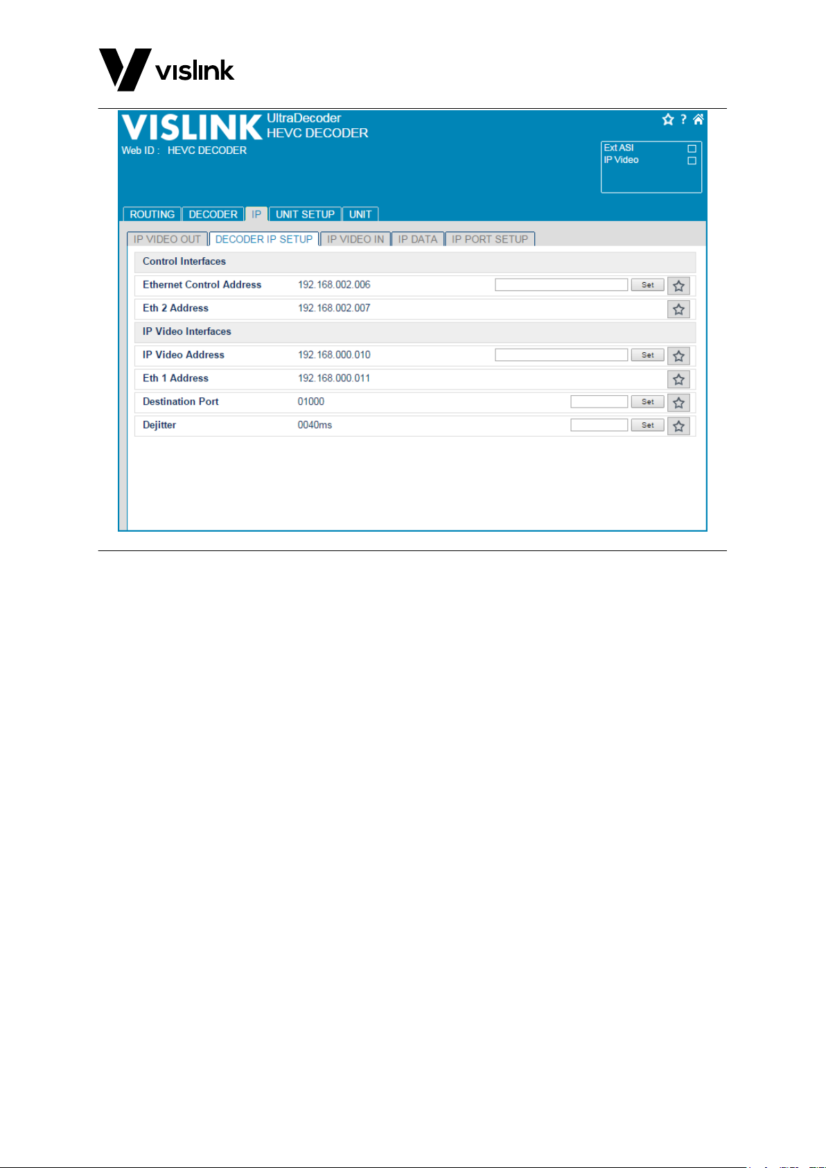
The unit should now be functioning correctly and will now be configured to use the default
IP addresses as shown in Figure B-1.
Page 46
UltraDecoder Operators Manual
Remote Control
Issue: 4 38
Ref: ULTD-ASUM-7001 Copyright © 2016 Vislink plc
Figure B-1 Web Interface Screen
Page 47
UltraDecoder Operators Manual
Remote Control
Issue: 4 39
Ref: ULTD-ASUM-7001 Copyright © 2016 Vislink plc
There is no routine maintenance required for this unit. However, it is good practice to
regularly check the unit has adequate airflow by keeping the rear and side ventilation grills
clear of obstructions.
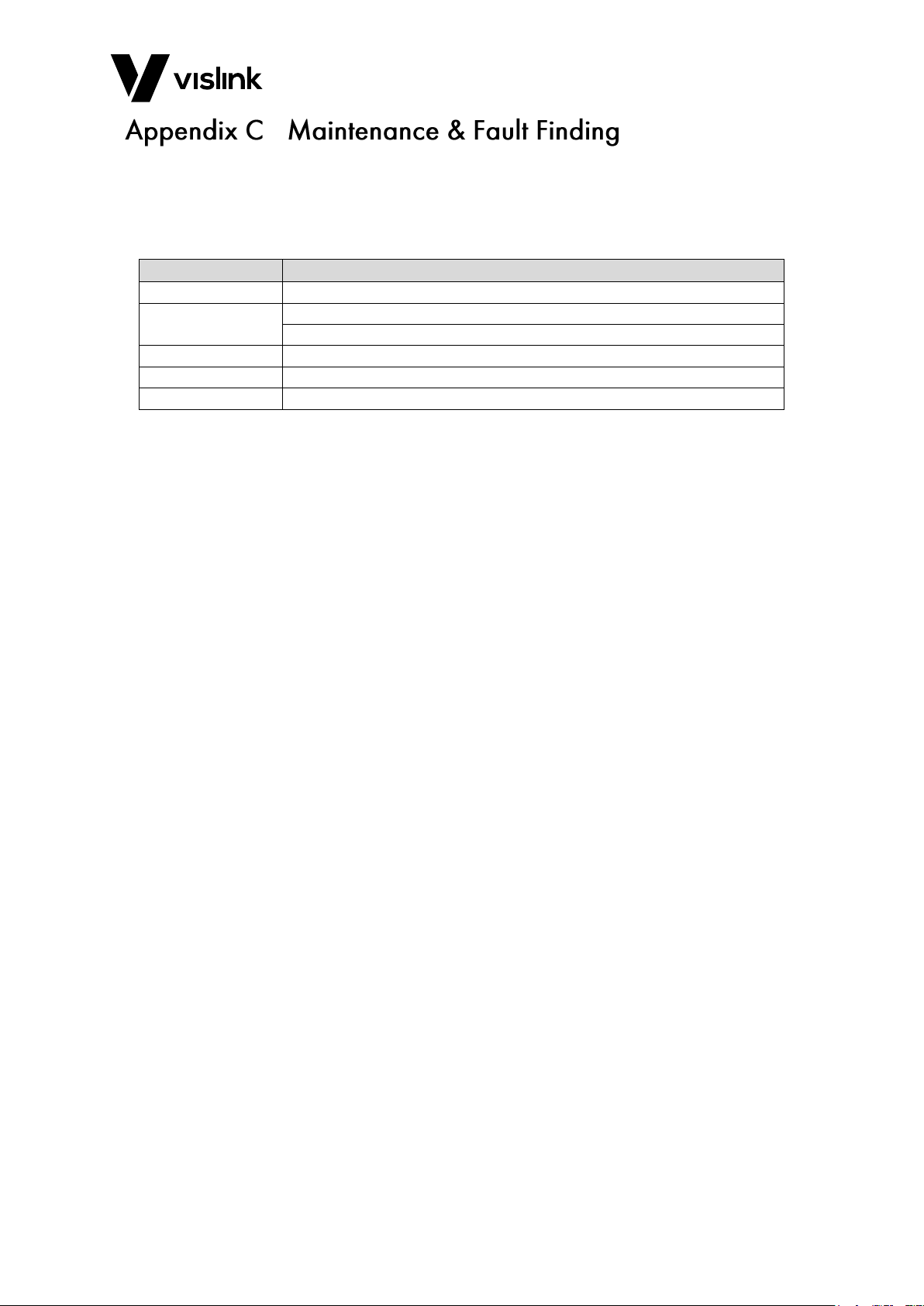
The following fault conditions may occur. The suggested remedial action is described.
Error Message
Suggested Remedial Action
Clock Error
Replace internal back up battery – refer to factory/agent.
Over Temperature
Check ventilation grilles on each side of unit are free of obstructions.
Check fans are running.
Encoder Fault
Restart unit. If the fault continues, refer to factory/agent.
Fan 1 Stopped
Refer to factory/agent for spares.
Fan 2 Stopped
Refer to factory/agent for spares.
Table C-1 Maintenance Error Table
Page 48

UltraDecoder Operators Manual
Remote Control
Issue: 4 40
Ref: ULTD-ASUM-7001 Copyright © 2016 Vislink plc
This page is intentionally unused.
Page 49
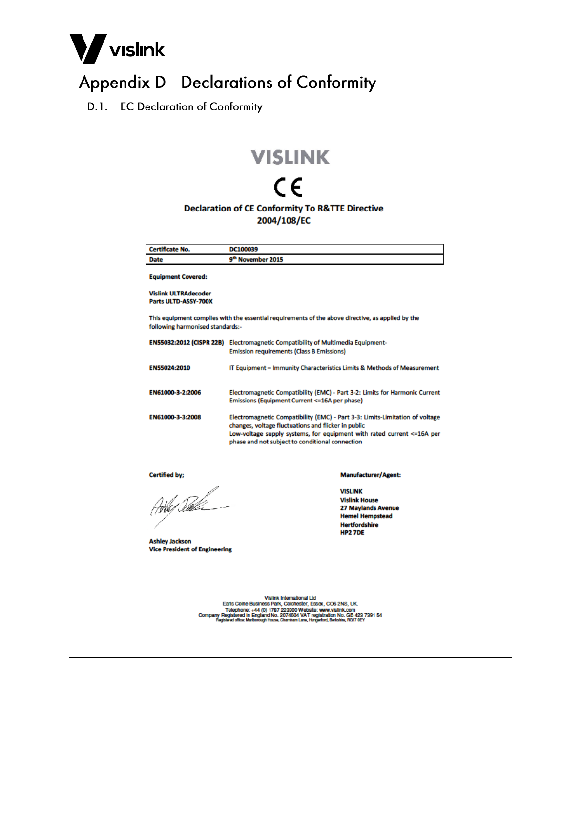
UltraDecoder Operators Manual
Remote Control
Issue: 4 41
Ref: ULTD-ASUM-7001 Copyright © 2016 Vislink plc
Page 50

UltraDecoder Operators Manual
Remote Control
Issue: 4 42
Ref: ULTD-ASUM-7001 Copyright © 2016 Vislink plc
This equipment has been tested and found to comply with the limits for a Class B digital
device, pursuant to part 15 of the FCC Rules. These limits are designed to provide
reasonable protection against harmful interference in a residential installation.
This equipment generates, uses and can radiate radio frequency energy and, if not installed
and used in accordance with the instructions, may cause harmful interference to radio
communications. However, there is no guarantee that interference will not occur in a
particular installation. If this equipment does cause harmful interference to radio or
television reception, which can be determined by turning the equipment off and on, the
user is encouraged to try to correct the interference by one or more of the following
measures:
Reorient or relocate the receiving antenna.
Increase the separation between the equipment and receiver.
Connect the equipment into an outlet on a circuit different from that to which the
receiver is connected.
Consult the dealer or an experienced radio/TV technician for help.
Properly shielded and grounded cables and connectors must be used to meet FCC emission
limits. Vislink Ltd is not responsible for any radio or television interference caused by using
other than recommended cables or connectors.
Unauthorized changes or modifications to the equipment could void the user’s authority to
operate the equipment.
These devices comply with part 15 of the FCC Rules. Operation is subject to the following
two conditions:
1. These devices may not cause harmful interference
2. These devices must accept any interference received, including interference that may
cause undesired operation.
This FCC Statement applies to these Vislink Ltd models:
UltraDecoder
Pertinent testing documentation is available for verification.
Page 51
UltraDecoder Operators Manual
Issue: 4 43
Ref: ULTD-ASUM-7001 Copyright © 2016 Vislink plc
Ultra Decoder MENU TREE
DECODER
SETUP
Note Some menus
dynamically change
depending on the mode of
operation.
UNIT
SETUP
System
continued
PRESETS
REMOTE
INTERFACES
RECALL FROM
MEMORY
STORE TO
MEMORY
USB TRANSFER
Name
Preset:
Recall
Presets from USB
Presets to USB
TIMEETHERNET PORT WEB IDENTIFIER
Restore Defults
Mask
IP
Gway
MAC
ID:
SERVICE HELP
Name
Preset:
Store
LICENCES MISCELLANEOUS
Line 1
ESN
Line 2
State
Date
Time
Format
Run Hours
Contrast
Lamp test
Fault Test
Reboot
DECODER
VERSION
UNIT VERSION SUPPORT
VIDEO AUDIO
DE-
SCRAMBLING
Program
Number:
Format:
Restart
decoder
Audio 1 PID:
Audio 2 PID:
Audio 4 PID:
Audio 3 PID:
De-
scrambling:
Type:
Key:
Test Pattern
RESTORE
DEFAULTS
Restore Defults
IP OPTIONS
ASI OPTIONS
DECODER
INPUT
IP VIDEO IN
IP PORT
SETUP
Ip Output:
MORE>
Dest:
Encap:
Dest Port:
TS PKTS per
IP
Addr:
Mask:
Traffic:
Gway:
ASI Out:
ASI Out Mode:
Decoder Input:
IP VIDEO
OUT
Port:
Status:
Page 52

UltraDecoder Operators Manual
Issue: 4 44
Ref: ULTD-ASUM-7001 Copyright © 2016 Vislink plc
This page is intentionally unused.
 Loading...