

Page 1

Vislink, Waterside House, Earls Colne Business Park, Colchester, Essex, CO6 2NS, UK
Telephone: +44 (0)1442 431300 ● Facsimile: +44 (0) 1494 775356 ● Email: [email protected] ● Website: www.vislink.com
Company Registered in England & Wales no. 10523708 ● VAT registration no. GB 260 012 169
Registered Office: Waterside House, Earls Colne Business Park, Colchester, Essex, CO6 2NS, UK
RCD9
2/4-Way Diversity
Receiver
User Manual
Page 2

Issue No: 1 Page: ii
Ref: RCD9-ASUM-7001 Copyright © 2017 IMT Ltd, trading as Vislink
Document Disclaimer
The information contained in this manual remains the property of Vislink and may not be
used, disclosed or reproduced in any other form whatsoever without the prior written
permission of Vislink.
Vislink reserves the right to alter the equipment and specification appertaining to the
equipment described in this manual without notification.
This document is supplied on the express terms that it is to be treated as confidential and
that it may not be copied, used or disclosed to others for any purpose except as authorized
by Vislink.
Conventions
NOTE: Notes show to convey additional information.
CAUTION: Cautions show where potential equipment damage could occur.
WARNING: Warnings show where there is potential for personal danger or risk of death.
Read all warnings and understand them before carrying out work on any
equipment. This includes peripherals and any related equipment in use. The
danger is real and not reading and understanding the warning could lead to
injury, harm or potential death.
Service/Support Contacts:
Region
Contact Details
Worldwide
+44 (0) 1442 431410
Americas
+1 978 330 9292
When contacting Technical Support, please include the following information:
Model number and serial number of the unit (located on a label on the bottom of
each unit).
………………………………………….
Approximate date of purchase.
………………………………………….
Page 3

Issue No: 1 Page: iii
Ref: RCD9-ASUM-7001 Copyright © 2017 IMT Ltd, trading as Vislink
Document History
Version
Date
Modification
Firmware Version
1
9//8/2017
First release of document.
-
Page 4

Issue No: 1 Page: iv
Ref: RCD9-ASUM-7001 Copyright © 2017 IMT Ltd, trading as Vislink
Table of Contents
1. General Information .................................................................................................. 1
General Safety Information ........................................................................................................ 1
Disposal Instructions .................................................................................................................. 2
Environmental ............................................................................................................................ 2
Health & Safety .......................................................................................................................... 3
Maximum RF Power Density Limits ........................................................................................... 4
2. Introduction .............................................................................................................. 5
3. Specifications ............................................................................................................ 7
Dual Diversity Receiver Head Unit ............................................................................................. 7
2/4-way Diversity Receiver Control Unit .................................................................................... 8
4. MVL-HD3 Diversity Control Unit ............................................................................... 11
Front Panel Layout ................................................................................................................... 11
Rear Panel Layout .................................................................................................................... 11
Connectors and Pinouts ........................................................................................................... 11
4.3.1. Mains Power ............................................................................................................................ 11
4.3.2. DC Power.................................................................................................................................. 12
4.3.3. ANALOGUE VIDEO OUTPUT ..................................................................................................... 12
4.3.4. SDI/ASI OUTPUTS (2) ................................................................................................................ 12
4.3.5. ANALOGUE AUDIO ................................................................................................................... 13
4.3.6. DIGITAL AES3/EBU AUDIO AND DOLBY PASS-THROUGH ........................................................ 13
4.3.7. USB Port ................................................................................................................................... 14
4.3.8. Ethernet Remote (rear panel connector) ................................................................................ 14
4.3.9. HDMI ........................................................................................................................................ 14
4.3.10. TSoIP ...................................................................................................................................... 14
4.3.11. Option (front panel connector) ............................................................................................. 14
4.3.12. Data (front panel connector) ................................................................................................. 14
4.3.13. Triax ....................................................................................................................................... 14
5. Dual Diversity Receiver Head Unit ............................................................................ 15
Connectors and Pin Outs .......................................................................................................... 15
5.1.1. RF Inputs .................................................................................................................................. 15
5.1.2. Triax Connector ........................................................................................................................ 15
5.1.3. DC Input ................................................................................................................................... 15
5.1.1. Remote ..................................................................................................................................... 15
6. Control Menus and Receiver Operation ................................................................... 17
On/Off Switches ....................................................................................................................... 17
Status LED ................................................................................................................................. 17
Local LED .................................................................................................................................. 17
Operator Controls .................................................................................................................... 17
Video Monitoring on the Front Panel LCD Screen ................................................................... 17
Receiver Current Status and Alarm Screens ............................................................................ 17
6.6.1. Overview Screen ...................................................................................................................... 18
Page 5
Issue No: 1 Page: v
Ref: RCD9-ASUM-7001 Copyright © 2017 IMT Ltd, trading as Vislink
6.6.2. Additional Status and Alarm Screens ....................................................................................... 18
Signal Status .......................................................................................................................... 18
Service Information............................................................................................................... 19
Decoder Status ...................................................................................................................... 19
Unit Information & Alarms ................................................................................................... 19
Setup Menus ............................................................................................................................ 20
6.7.1. Channel Frequency Menu ........................................................................................................ 20
Channel ................................................................................................................................. 20
Preset Config. ........................................................................................................................ 20
Channel Config ...................................................................................................................... 20
Spectrum and Bandwidth ..................................................................................................... 21
6.7.2. Inputs Menu ............................................................................................................................. 21
Demodulator ......................................................................................................................... 21
Decoder ................................................................................................................................. 21
6.7.3. Outputs Menu .......................................................................................................................... 21
Analogue Outputs ................................................................................................................. 21
Digital Outputs ...................................................................................................................... 21
6.7.4. Ports Menu .............................................................................................................................. 22
User Data .............................................................................................................................. 22
Ethernet ................................................................................................................................ 22
6.7.5. ASI Over IP Menu ..................................................................................................................... 22
6.7.6. General Settings Menu ............................................................................................................ 22
Software Versions ................................................................................................................. 22
Display ................................................................................................................................... 22
Unit Name ............................................................................................................................. 22
Temperatures........................................................................................................................ 23
Advanced Mode .................................................................................................................... 23
USB Upgrade ......................................................................................................................... 23
Receiver Menu Tree ................................................................................................................. 23
7. Preparing for Operation ........................................................................................... 29
Equipment Operation............................................................................................................... 29
MVL HD3 Diversity Receiver ..................................................................................................... 29
7.2.1. Antennas .................................................................................................................................. 29
7.2.2. Checks ...................................................................................................................................... 29
Transmitter/Receiver Tests ...................................................................................................... 29
Page 6

Issue No: 1 Page: vi
Ref: RCD9-ASUM-7001 Copyright © 2017 IMT Ltd, trading as Vislink
Table of Figures
Figure 4-1 Front Panel Layout ...................................................................................................... 11
Figure 4-2 Rear Panel Layout ........................................................................................................ 11
Figure 6-1 Overview Screen.......................................................................................................... 18
Figure 6-2 Signal Status Overview ................................................................................................ 18
Figure 6-3 Service Information Screen ......................................................................................... 19
Figure 6-4 Decoder Status Screen ................................................................................................ 19
Figure 6-5 Unit Information & Alarms Screens ............................................................................ 19
Figure 6-6 Setup Menus ............................................................................................................... 20
Figure 6-7 Channel Screen ............................................................................................................ 20
Table of Tables
Table 3-1 Dual Diversity Receiver Specification ............................................................................ 7
Table 3-2 2/4-way Diversity Receiver Specification ...................................................................... 9
Table 4-1 Mains Power Pinouts................................................................................................... 11
Table 4-2 Mains Power Pinouts................................................................................................... 12
Table 4-3 Analogue Audio Pinouts .............................................................................................. 13
Table 4-4 Digital Audio & Dolby Pass-through ............................................................................ 13
Table 4-5 Data Pinouts ................................................................................................................ 14
Table 5-1 DC Input Pinouts .......................................................................................................... 15
Table 5-2 Remote Pinouts ........................................................................................................... 15
Table 6-1 Status LED Overview ................................................................................................... 17
Table 6-2 Local LED Overview ..................................................................................................... 17
Table A-1 DVB-T Bit Rates for 6, 7 & 8MHz ................................................................................. 31
Table B-1 Glossary of Terms ........................................................................................................ 32
Page 7
RCD9 Receiver Operators Manual
General Information
Issue No: 1 Page: 1
Ref: RCD9-ASUM-7001 Copyright © 2017 IMT Ltd, trading as Vislink
1. General Information
General Safety Information
To ensure awareness of potential hazards, all personnel concerned with the operation or
maintenance of the equipment must study the information that follows, together with
local site regulations.
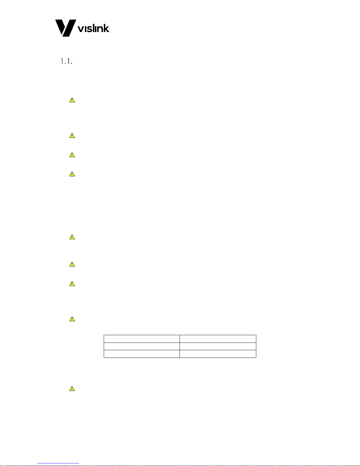
WARNING: RF Power Hazard: High levels of RF power are present in the unit. Exposure to
RF or microwave power can cause burns and may be harmful to health. Switch
off supplies before removing covers or disconnecting any RF cables, and before
inspecting damaged cables or antennas.
WARNING: Avoid standing in front of high gain antennas (such as a dish) and never look
into the open end of a waveguide or cable where RF power may be present.
CAUTION: Users are strongly recommended to return any equipment that requires RF
servicing to Vislink.
WARNING- GaAs / BeO Hazard: Certain components inside the equipment contain Gallium
Arsenide and Beryllium Oxide that are toxic substances. Whilst safe to handle
under normal circumstances, individual components must not be cut, broken
apart, incinerated or chemically processed. In the case of Beryllium Oxide, a
white ceramic material, the principal hazard is from the dust or fumes, which
are carcinogenic if ingested, inhaled or entering damaged skin.
Please consult your local authority before disposing of these components.
CAUTION: Tantalum Capacitors: When subjected to reverse or excess forward voltage,
ripple current or temperature these components may rupture and could
potentially cause personal injury.
CAUTION: This system contains MOS devices. Electro-Static Discharge (ESD) precautions
should be employed to prevent accidental damage.
CAUTION – AC supply connection and protective earth: The MVL-HD3 series control unit is
a Class 1 device and when used with an AC supply must be connected to a
protective earth. Failure to provide this earth may result in high voltages on the
unit chassis. Installation should always follow local wiring regulations.
The equipment is supplied with an AC supply connector and cord assembly. The wires in
the cord is colored in accordance with the following convention:
Green & Yellow:
Earth (Ground)
Blue
Neutral
Brown
Live
Always ensure that the equipment is correctly connected. Failure to connect the
equipment correctly may render protective devices inoperative; if in doubt consult a
qualified electrician.
CAUTION: The equipped front panel on/off switch is a standby function only. Some
components remain powered. An AC isolator switch is fitted on the rear panel
adjacent to the AC input connector; in normal use, the equipment should be
positioned such that this switch remains readily accessible. To be certain that
Page 8

RCD9 Receiver Operators Manual
General Information
Issue No: 1 Page: 2
Ref: RCD9-ASUM-7001 Copyright © 2017 IMT Ltd, trading as Vislink
the equipment is isolated from the AC supply; always unplug it from the AC
outlet.
Disposal Instructions
WARNING: DO NOT incinerate batteries. Exposing batteries to naked flames or extreme
heat sources can cause them to rupture or explode.
DO NOT dispose of any of the supplied equipment as household waste. The supplied
equipment is not biodegradable in landfill sites. For safe disposal of the supplied
equipment, take it to your local (council/authority) environmental waste site. For details,
contact your local authority/recycling center.
NOTE: In Europe dispose of all equipment in accordance with the European Environmental
directive.
Environmental
CAUTION: The unit is IP0x rated and must be protected from dripping or splashing
water/fluids. When used outdoors, protect the unit using a rain cover.
Page 9
RCD9 Receiver Operators Manual
General Information
Issue No: 1 Page: 3
Ref: RCD9-ASUM-7001 Copyright © 2017 IMT Ltd, trading as Vislink
Health & Safety
Exposure to Non-Ionizing (RF) Radiation/Safe Working Distances
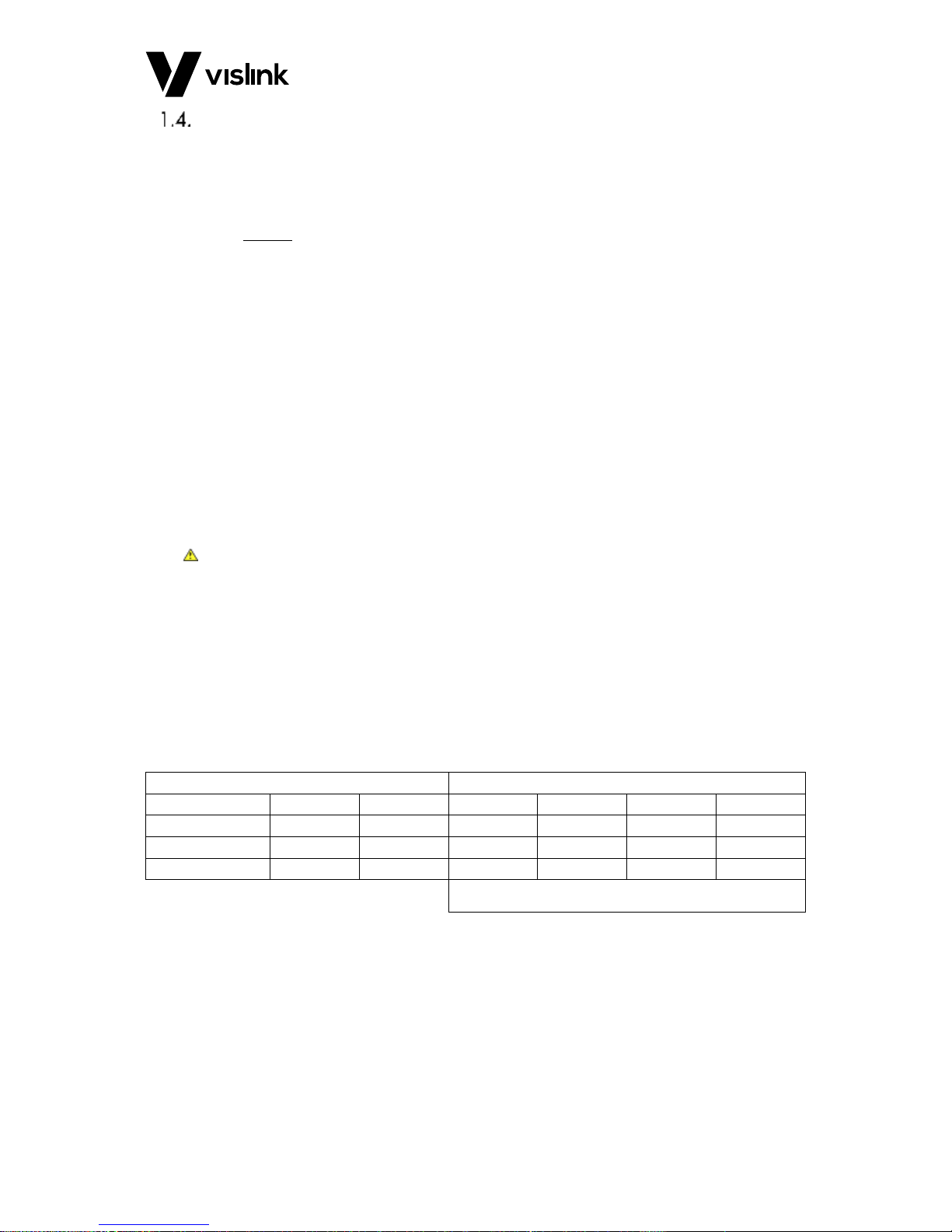
The safe working distance from a transmitting antenna may be calculated from the
relationship:
D =
in which D = safe working distance (meters)
PT = transmitter or combiner power output (watts)
GR = antenna gain ratio = anti log (gain dBi ÷10)
w = Maximum allowed power density (watts/square meter)
The RF power density value is determined by reference to safety guidelines for exposure of
the human body to non-ionizing radiation. It is important to note that the guidelines
adopted differ throughout the world and are from time-to-time re-issued with revised
guidelines. For Vislink use, a maximum power density limit (w) of 1w/m² is to be applied
when calculating minimum safe working distances. Appendix A refers.
WARNING: Any transmitting equipment, radiating power at frequencies of 100 kHz and
higher, has the potential to produce thermal and athermal effects upon the
human body.
To be safe:
a. Operators should not stand or walk in front of any antenna, nor should they
allow anyone else to do so.
b. Operators should not operate any RF transmitter or power amplifier with any of
its covers removed, nor should they allow anyone else to do so.
Worked examples:
Antenna
Transmitter Power
Type
Gain (dBi)
Gain Ratio
2W
4W
10W
30W
OMNI
4
2.5 1 1
1.5
2.5
HELIX
20
100 4 5.6 9 15.5
PARABOLIC DISH
35
3,162
22.5
32
50
87
MINIMUM SAFE DISTANCE (METRES)
PT. GR
Page 10

RCD9 Receiver Operators Manual
General Information
Issue No: 1 Page: 4
Ref: RCD9-ASUM-7001 Copyright © 2017 IMT Ltd, trading as Vislink
Maximum RF Power Density Limits
The RF Radiation Power Density limit figure recommended by Vislink is based upon
guideline levels published in:
a. IEEE standard C95.1 1999 - IEEE Standard for Safety Levels with respect to
Human Exposure to Radio Frequency Electromagnetic Fields, 3 kHz to 300 GHz.
b. Guidelines for Limiting Exposure to Time-varying Electric, Magnetic &
Electromagnetic Fields (up to 300 GHz) published in 1998 by the Secretariat of
the International Commission on Non-Ionizing Radiation Protection (ICNIRP).
Both documents define guideline RF power density limits for "Controlled" and
"Uncontrolled" environments. An uncontrolled environment is defined as one in which the
person subjected to the RF radiation may be unaware of and has no control over the
radiation energy received. The uncontrolled environment conditions can arise, even in the
best-regulated operations and for this reason, the limits defined for the uncontrolled
environment have been assumed for the Vislink recommended limit.
Documents a) and b) also show the RF power density guidelines to be frequency
dependent. Different power density / frequency characteristics are presented in the two
documents. To avoid complexity and to avoid areas of uncertainty, Vislink recommends
the use of a single power density limit across the frequency range 100 kHz to 300 GHz. The
1w/m² power density limit we recommend satisfies the most stringent of the guidelines
published to date.
NOTE: The IICNIRP document is freely available for download from the internet at
www.icnirp.de/emfgdl (PDF file) the IEEE standard is available on loan from Essex
County Library on payment of a search fee.
Page 11

RCD9 Receiver Operators Manual
Introduction
Issue No: 1 Page: 5
Ref: RCD9-ASUM-7001 Copyright © 2017 IMT Ltd, trading as Vislink
2. Introduction
The Diversity System is an extension to the highly successful MVL-HD series of microwave
links. The first truly digital microwave link to meet the requirements of digital television
outside broadcasts. The Diversity system is primarily used in conjunction with a mobile
Vislink transmitter; for example the D-Cam Clip-On unit wireless camera, “on-board”
transmitters, or as a central receiving station to provide 360-degree coverage for citywide
reception and helicopter downlinks.
This version of the receiver features both H264/MPEG-4 and MPEG-2 decoding with
automatic selection.
The Diversity Control Unit takes the form of a 2U 19” rack mounted unit. The associated RF
Head unit(s) are machined out of solid aluminum to provide exceptional mechanical
strength. They are of modular design for easy access and flexibility; the Diversity Control
Unit and Head units are connected together via Triax cable; the cable may be up to 600m
in length.
The output from the Receiver features a comprehensive range of signal formats for video
and audio, including HD and SD SDI video, PAL/NTSC analogue video, AES/EBU digital,
Dolby E and Dolby D pass-through, SDI embedded and analogue audio, together with IP
encapsulated ASI data and HDMI. In HD mode, a down-converted CVBS monitor output is
also provided.
The received video may be monitored on the front panel LCD color screen where security
clearance allows.
The menu control and monitoring uses six push buttons for ease of operation, and allows
the complete Receiver set-up to be controlled from the front panel. Remote monitoring
via Ethernet is also provided.
The Receiver will accept a wide range of AC and DC power options. Powering will
automatically switch to DC, with no break, in the event of a failure of the AC supply.
Page 12

RCD9 Receiver Operators Manual
Introduction
Issue No: 1 Page: 6
Ref: RCD9-ASUM-7001 Copyright © 2017 IMT Ltd, trading as Vislink
This page is intentionally unused.
Page 13
RCD9 Receiver Operators Manual
Specifications
Issue No: 1 Page: 7
Ref: RCD9-ASUM-7001 Copyright © 2017 IMT Ltd, trading as Vislink
3. Specifications
Dual Diversity Receiver Head Unit
NOTE: Vislink may alter these specifications its own discretion or to meet customer
requirements.
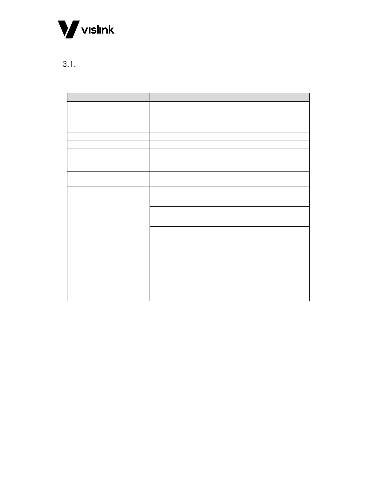
Feature
Details
Frequency Band
1.3 to 13GHz
Tuning Range
Up to 700MHz.
Frequency Selection
Up to sixteen pre-set channels, or tuning in 1MHz steps via front
panel control
Receiver Noise Factor
4dB (nom.)
Receive Antenna
Compatible with all Gigawave antennas
Bandwidth
Filtered for COFDM 8MHz bandwidth
IF Frequencies
1st IF in the range 800MHz nom. (depending on frequency band)
2nd IF 60 and 80MHz or 70MHz (system dependent)
Control and Monitoring*
Comprehensive remote control and monitoring via Ethernet
port/Web browser
Power Supply*
Triax powered, +48 VDC (nominal), 20 to 48 VDC max. derived
from the associated RX control unit
Directly powered, external input +20 to 50 VDC
Power consumption 70 to 110 Watts (varies with Triax cable
length and options)
Mechanical Interface
Mast, scaffold and special mounts available.
Size
150 x 111 x 152mm
Weight
1.6kg
Environmental
Safe use: -20° to +50°C
To spec: - 10° to +45°C
Altitude: 4500m
Humidity: 95% long term
Table 3-1 Dual Diversity Receiver Specification
NOTE: * indicates that one of the options is applicable
Page 14
RCD9 Receiver Operators Manual
Specifications
Issue No: 1 Page: 8
Ref: RCD9-ASUM-7001 Copyright © 2017 IMT Ltd, trading as Vislink
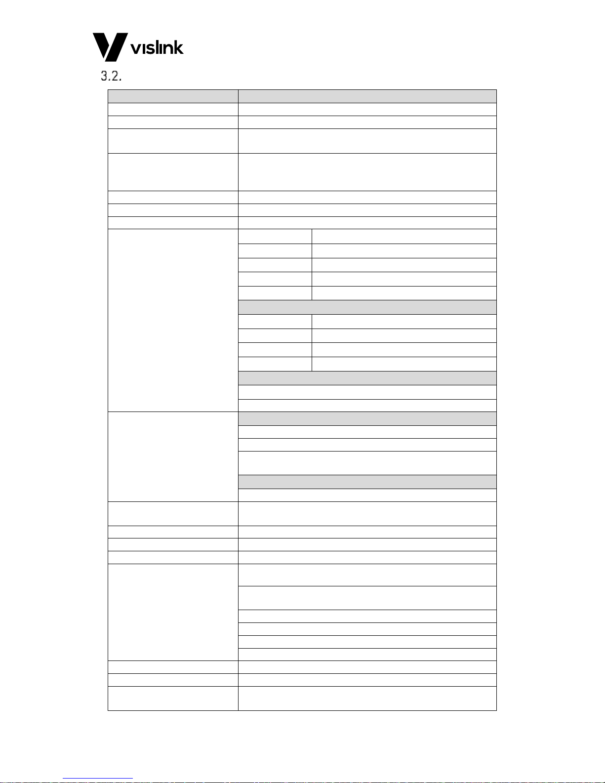
2/4-way Diversity Receiver Control Unit
Feature
Details
Input Connectors
2x or 4x mini Lemo Connectors, system dependent
Triax Separation
Up to 600m
Demodulation
2-way or 4-way Maximum Ratio Combining Diversity Reception
COFDM DVB-T 2k
Demodulation Modes
QPSK, 16QAM, 64QAM
FEC: 1/2 2/3 3/4 5/6 7/8
Guard interval: 1/32 1/16 1/8 1/4
Data Rate
4.98 to 31.7 Mbit/s (automatic selection)
Bandwidth
6, 7, 8 MHz
Decoding Modes
SD/HD MPEG-4/ H.264, SD/HD MPEG-2 (automatic selection)
Video Formats HD/SD
1080p
1920 x 1080
1080i
1920 x 1080
720p
1280 x 720
480i (NTSC)
720 x 480
576i (PAL)
720 x 576
Digital
SDI 3G
SMPTE-425M
SDI HD
SMPTE-292M (299M)
SDI SD
SMPTE-259M (272M)
HDMI
V1.3a
Analogue
Composite (PAL/NTSC)
HD to down-converted SD composite, monitoring quality.
Audio Outputs
Digital
2 x AES3/EBU
2 x stereo SDI embedded
Dolby D (AC3) and Dolby E pass-through via SDI embedded and
AES
Analogue
2 x stereo / 4 x mono outputs
Latency
Automatic selection down to sub 1 frame (20ms), transmitter
encoding profile dependent
ASI/SDI Output
ASI transport stream (qty2) 188 byte
TSoIP
UDP, RTP, Unicast and Multicast Ethernet IP protocol
User Data Output
1200 to 230,400 baud “User Data” channel
Monitoring
Video picture monitoring on the full color LCD front panel display
Comprehensive control and monitoring menu via front panel
control
COFDM demodulator parameters
RF Received signal level (dBm and bar graph)
C/N, MER, BER (dB and bar graph)
Internal lock alarms
Remote Control
Remote control and monitoring via Ethernet port
USB Upgrade Port
USB port for internal software upgrade
Power Requirements
Universal supply 100-240VAC (auto sensing) plus 12 - 36VDC
(75W)
Page 15

RCD9 Receiver Operators Manual
Specifications
Issue No: 1 Page: 9
Ref: RCD9-ASUM-7001 Copyright © 2017 IMT Ltd, trading as Vislink
Feature
Details
Size
2U 19” rack 390mm deep
Weight
7kg
Environmental
Safe use: -20° to +50°C
To spec: -10° to +45°C
Altitude: 4500m
Humidity: 95% long term
IP Rating: IP0X
Table 3-2 2/4-way Diversity Receiver Specification
Page 16

RCD9 Receiver Operators Manual
Specifications
Issue No: 1 Page: 10
Ref: RCD9-ASUM-7001 Copyright © 2017 IMT Ltd, trading as Vislink
This page is intentionally unused.
Page 17
RCD9 Receiver Operators Manual
MVL-HD3 Diversity Control Unit
Issue No: 1 Page: 11
Ref: RCD9-ASUM-7001 Copyright © 2017 IMT Ltd, trading as Vislink
4. MVL-HD3 Diversity Control Unit
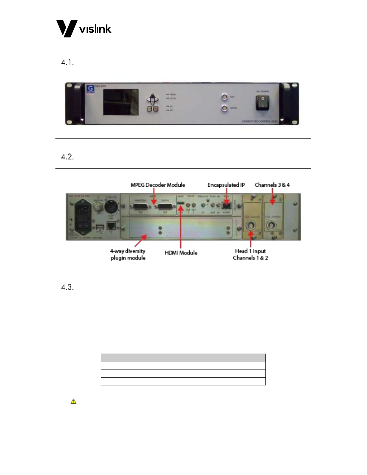
Front Panel Layout
Figure 4-1 Front Panel Layout
Rear Panel Layout
Figure 4-2 Rear Panel Layout
Connectors and Pinouts
4.3.1. Mains Power
Input range: 100V to 240VAC 50/60Hz.
Replacement type of the mains fuse: 5x20mm, Time Lag 3.15A, 250V
Fuse breaking capacity: UL: 10kA @125V AC, IEC: 1.5kA @ 250V AC.
Connector type: Fused IEC Inlet
Pin
Function
E
Earth
L
Live N Neutral
Table 4-1 Mains Power Pinouts
CAUTION: If no earth is present on the AC mains lead, connect an independent earth to the
MVL-HD3 control unit. A fixing point is provided on the rear panel for this
purpose. For further power information for the unit, see AC supply connection
and protective earth in Section 1.1 above.
Page 18
RCD9 Receiver Operators Manual
MVL-HD3 Diversity Control Unit
Issue No: 1 Page: 12
Ref: RCD9-ASUM-7001 Copyright © 2017 IMT Ltd, trading as Vislink
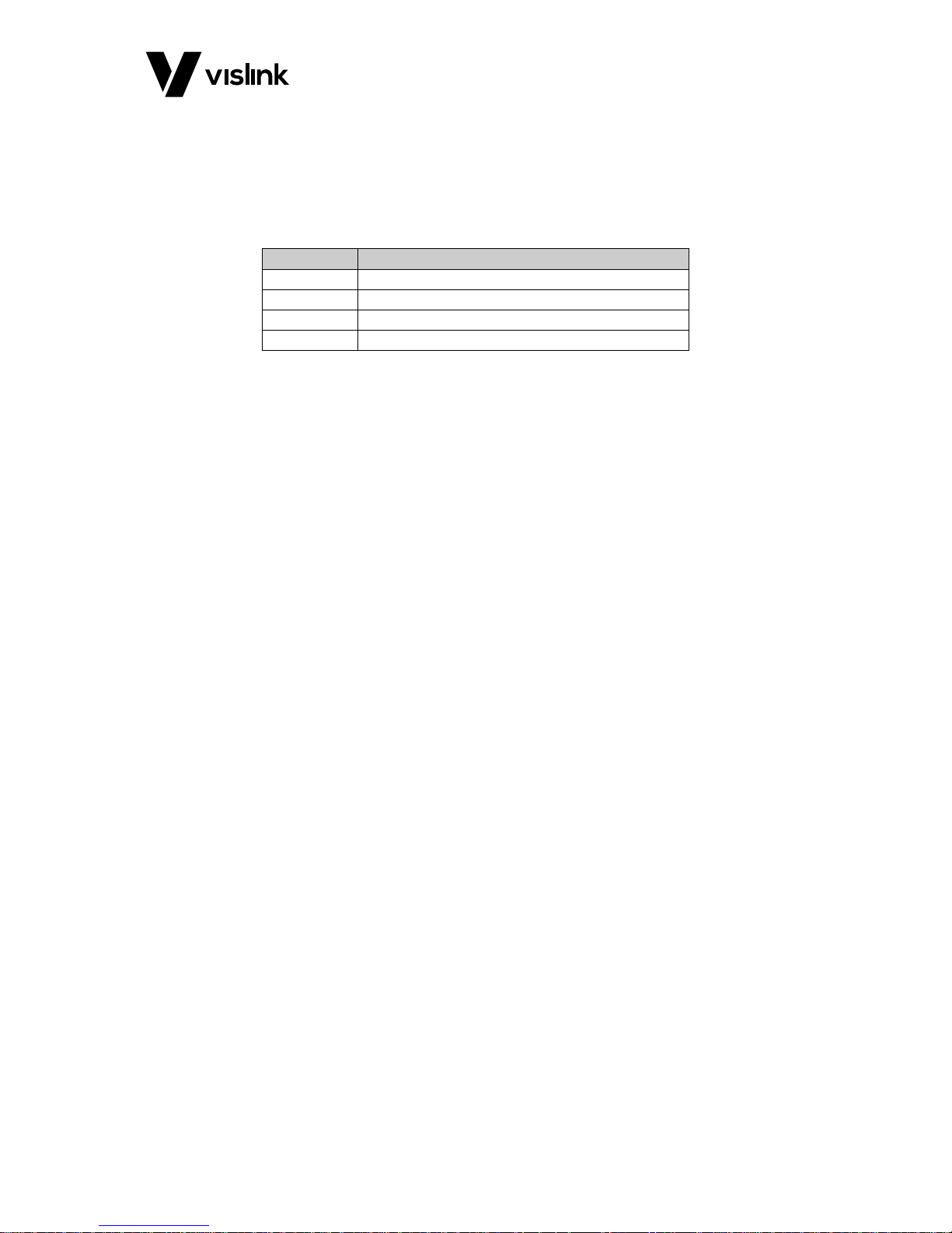
4.3.2. DC Power
Input range: 12V to 36V DC.
This DC input provides power to both the MVL-HD2 Receive Control unit and the Receive
Head unit(s) via the Triax cable.
Connector type: 4-Pin XLR Male
Pin
Function
1
0V / Gnd
2
NC 3 NC 4 +12 to 36V DC
Table 4-2 Mains Power Pinouts
4.3.3. ANALOGUE VIDEO OUTPUT
Connector type: HD-BNC
Output of Composite video (CVBS) when the system is in SD mode.
HD down-converted to analogue (monitoring quality) when the system is in HD mode.
4.3.4. SDI/ASI OUTPUTS (2)
Two-connector type: HD-BNC
The connectors can be independently configured to provide either HD or SD SDI video
(with embedded audio / Dolby audio) or ASI. See Section 6.7.3.2 for details of output
selection.
Page 19
RCD9 Receiver Operators Manual
MVL-HD3 Diversity Control Unit
Issue No: 1 Page: 13
Ref: RCD9-ASUM-7001 Copyright © 2017 IMT Ltd, trading as Vislink
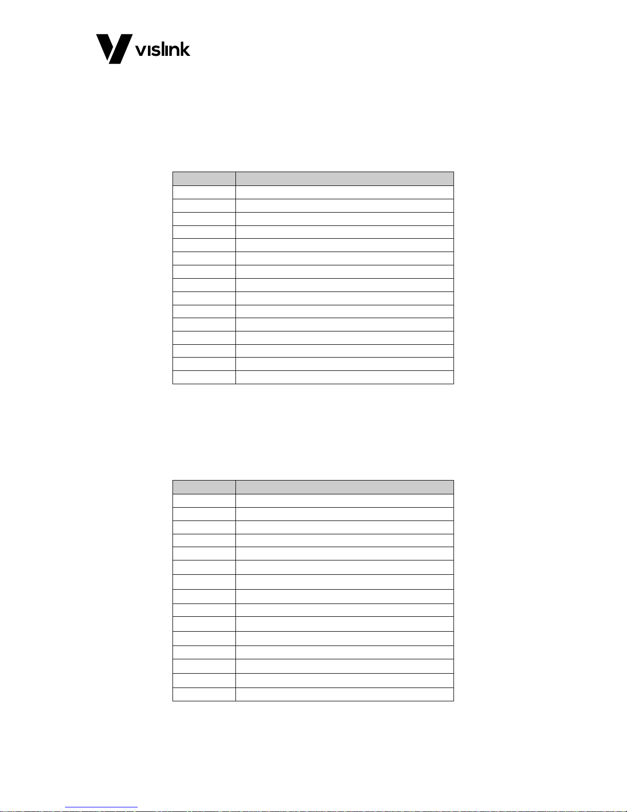
4.3.5. ANALOGUE AUDIO
PL8 connector type: 15-way D-type
The four mono-channels of analogue audio (on the MPEG decoder plug-in card) connect to
a single D-type connector. You can independently select these outputs as 600 Ohm or
Low-Z impedance and the outputs have +5/-20dB adjustable gain fitted. See Section 6
below for details.
Pin
Analogue Audio
1
Ch1 / A / Left +ve
2
0V 3 Ch2 / A / Right -ve
4
Ch3 / B / Left +ve
5
0V 6 Ch4 / B / Right -ve
7
NC 8 NC 9 Ch1 / A / Left -ve
10
Ch2 / A / Right +ve
11
0V
12
Ch3 / B / Left -ve
13
Ch4 / B / Right +ve
14
0V
15
0V
Table 4-3 Analogue Audio Pinouts
4.3.6. DIGITAL AES3/EBU AUDIO AND DOLBY PASS-THROUGH
PL9 connector type: 15-way D type
The four mono audios are configured in AES digital audio as two stereo pairs (pair 1 and
pair 2). If Dolby is in use, it always uses pair 2.
Pin
Digital Audio
1
Pair 1 +ve
2
Pair 1 0V
3
NC 4 Pair 2 +ve, or Dolby pass-through
5
Pair 2 0V
6
NC 7 NC 8 NC
9
Pair 1 -ve
10
NC
11
NC
12
Pair 2 –ve, or Dolby pass-through
13
NC
14
NC
15
0V
Table 4-4 Digital Audio & Dolby Pass-through
Page 20
RCD9 Receiver Operators Manual
MVL-HD3 Diversity Control Unit
Issue No: 1 Page: 14
Ref: RCD9-ASUM-7001 Copyright © 2017 IMT Ltd, trading as Vislink
4.3.7. USB Port
This port may be used to allow software in the Receiver control unit to be updated. Please
see Section 6.7.6.6.
4.3.8. Ethernet Remote (rear panel connector)
Connector type: RJ11
The Ethernet port on the connector panel may be used for remote control and monitoring
of the receiver.
4.3.9. HDMI
Connector type: Type C HDMI 1.3a
4.3.10. TSoIP
Connector type: RJ11
The TSoIP Ethernet port allows easy transportation of encapsulated ASI over an IP Ethernet
networking system.
4.3.11. Option (front panel connector)
Connector type: LEMO 7way EGG.1B.307.CLL
This connector is available for future application.
4.3.12. Data (front panel connector)
Connector type: LEMO connector EGG.1B.307.CLL
Allows ‘User Data’ RS 232 or R485 to be output from the ASI Transport stream.
Pin
Function
Direction
1
0v
NC 2 User Data Tx -n RS232
Out from Unit
3
User Data Rx –n RS232
Into Unit
4
User TX p RS485
NC 5 User TX n RS485
NC 6 User RX_p RS485
NC 7 User RX_n RS485
NC
Table 4-5 Data Pinouts
4.3.13. Triax
Connector type: LEMO connector FFA.2S.675.CTA C87Z
Two or four triaxial connectors carry DC power, 60MHz/80MHz IF and serial control /
status data between the Diversity Unit and Head units.
Page 21
RCD9 Receiver Operators Manual
Dual Diversity Receiver Head Unit
Issue No: 1 Page: 15
Ref: RCD9-ASUM-7001 Copyright © 2017 IMT Ltd, trading as Vislink
5. Dual Diversity Receiver Head Unit
Connectors and Pin Outs
5.1.1. RF Inputs
Connector type: N type
5.1.2. Triax Connector
Connector type: LEMO connector FBD.4E.675.CTL
Input range: +48 VDC nominal (20V to 48 VDC)
NOTE: The Dual RF Head Unit may derive its power either from the Triax (normal method),
or from the separate Lemo, see Section 5.1.3.
5.1.3. DC Input
Connector type: LEMO connector EGG-1K-303-CLL
Input range: 20V to 50VDC
Pin
Function
1
0V / Gnd
2
NC 3 +20 to +50V DC
Table 5-1 DC Input Pinouts
5.1.1. Remote
Connector type: LEMO connector EGA 0K 307 CLL
A seven-pin connector is used to provide an analogue voltage representing the received RF
level (0 to 5V into a load of 5k Ohms or more). This provides a convenient AGC metering
aid for alignment of the antenna. The same connector has an RS485 serial interface for
factory set up.
Pin
Function
Direction
1
0v - 2
RF level voltage
Out from unit
3
NC
NC 4 RS485 Tx+
Out from Unit
5
RS485 Tx- / RS232 Tx
Out from Unit
6
RS485 Rx-
Into Unit
7
RS485 Rx- / RS232 Rx
Into Unit
Table 5-2 Remote Pinouts
Page 22

RCD9 Receiver Operators Manual
Dual Diversity Receiver Head Unit
Issue No: 1 Page: 16
Ref: RCD9-ASUM-7001 Copyright © 2017 IMT Ltd, trading as Vislink
This page is intentionally unused.
Page 23
RCD9 Receiver Operators Manual
Control Menus and Receiver Operation
Issue No: 1 Page: 17
Ref: RCD9-ASUM-7001 Copyright © 2017 IMT Ltd, trading as Vislink
6. Control Menus and Receiver Operation
On/Off Switches
There are two on/off switches on the unit.
The rear panel switch isolates the AC input from the unit and is provided for safety reasons
to isolate the unit.
The front panel switch is a unit standby switch and in the O position de-powers the main
circuitry of the unit when powered from AC or DC; some circuitry inside the unit remains
powered. For further information, see AC supply connection and protective earth in
Section 1.1.
Status LED
The front panel status LED is used to indicate the general condition of the unit.
State
Description
Green
Normal healthy condition
Flashing Green
Unit is OK, however there is no video (or ASI) transport stream
from the transmitter
Red
Fault or warning
Table 6-1 Status LED Overview
Local LED
State
Description
Green
Indicates configuration is possible by LCD front panel and
remote PC software.
Table 6-2 Local LED Overview
Operator Controls
The MVL-HD3 Diversity Receiver is configured using an LCD display and six push buttons.
These are arranged as four navigation buttons (▲▼◄►), OK and ESC (escape).
The OK button is used to store a modified parameter in non-volatile memory, this
parameter will be used to configure the unit and will become the default value when next
powered on. Use the ESC button to exit a menu without storing the parameter in memory.
Video Monitoring on the Front Panel LCD Screen
Received video picture monitoring is available on the full color front panel LCD screen
where security clearance allows.
To access the function, navigate to the Overview screen by repeatedly pressing the ESC
button. Use the ◄ ► keys to navigate between the status screens and video display.
Receiver Current Status and Alarm Screens
These screens show the status of the unit and any alarms present.
Page 24
RCD9 Receiver Operators Manual
Control Menus and Receiver Operation
Issue No: 1 Page: 18
Ref: RCD9-ASUM-7001 Copyright © 2017 IMT Ltd, trading as Vislink
6.6.1. Overview Screen
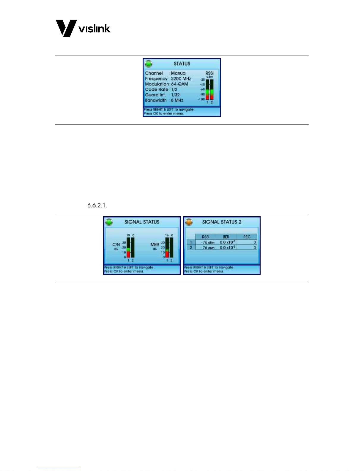
Figure 6-1 Overview Screen
This is the display screen during normal operation of the MVL-HD Diversity Receiver and
indicates the Channel number, and Rx frequency. Provided the receiver is receiving a
signal from the transmitter, the display will show the modulation, the spectrum bandwidth
and the receiver input levels for the two or four antenna inputs.
6.6.2. Additional Status and Alarm Screens
Access these screens from the Overview screen by repeatedly pressing the ► button.
Signal Status
Figure 6-2 Signal Status Overview
The following functions display:
Carrier to noise (C/N) for the two or four RF inputs
MER (modulation error ratio)
Received signal level (RSSI)
Bit error rate (BER)
Packet error count (PEC) - Use ESC to clear errors
Page 25
RCD9 Receiver Operators Manual
Control Menus and Receiver Operation
Issue No: 1 Page: 19
Ref: RCD9-ASUM-7001 Copyright © 2017 IMT Ltd, trading as Vislink
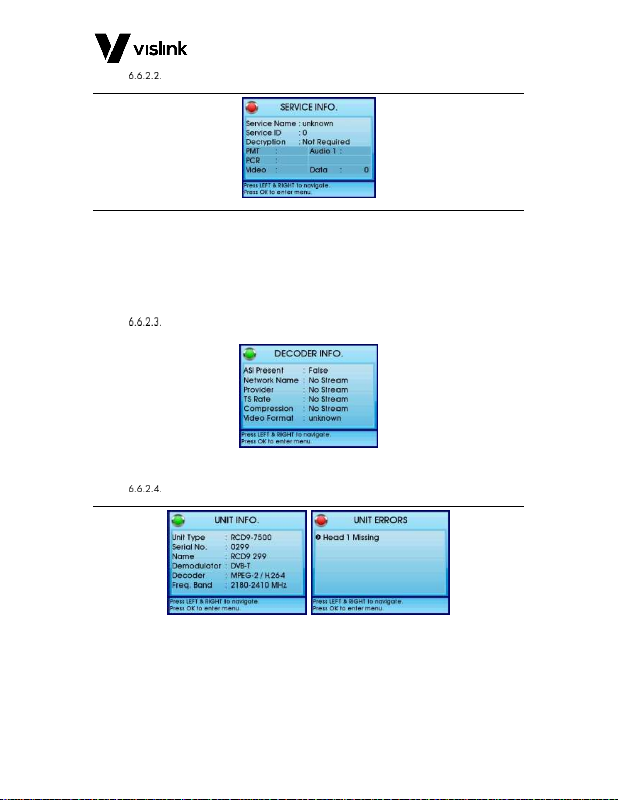
Service Information
Figure 6-3 Service Information Screen
The following functions display:
Service name
Service ID
Decryption status
Transport stream PIDs
Decoder Status
Figure 6-4 Decoder Status Screen
Unit Information & Alarms
Figure 6-5 Unit Information & Alarms Screens
These screens provide unit hardware information and the alarm status of individual
modules within the receiver.
Page 26
RCD9 Receiver Operators Manual
Control Menus and Receiver Operation
Issue No: 1 Page: 20
Ref: RCD9-ASUM-7001 Copyright © 2017 IMT Ltd, trading as Vislink
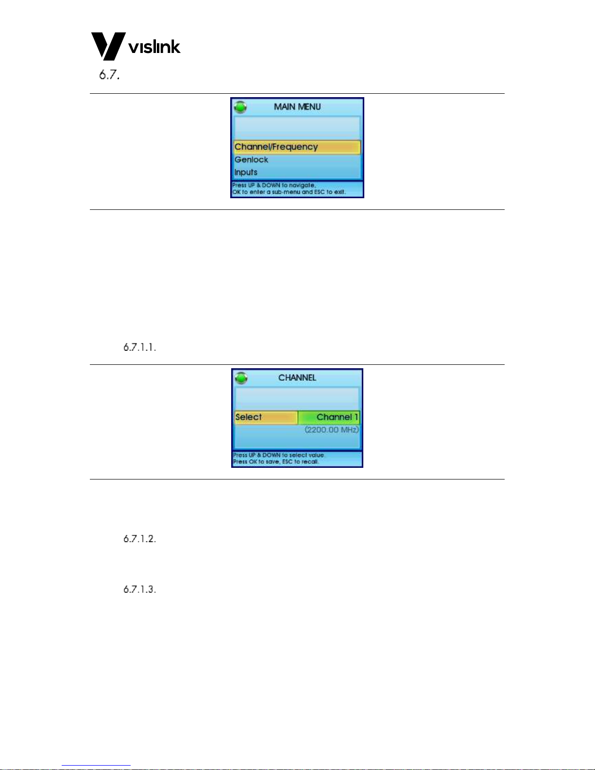
Setup Menus
Figure 6-6 Setup Menus
To access the setup menus press the ESC button several times to reach the Overview
screen and then press the OK button. Use the ▲▼ keys to reach the required setup
function and press the OK button.
NOTE: The functions displayed in the setup menus are dependent on whether “Advanced
mode” is set to Enabled or Disabled in the General settings menu. The Advanced
mode provides additional features and is password protected. – see Section 6.7.6.5.
6.7.1. Channel Frequency Menu
Channel
Figure 6-7 Channel Screen
This menu is used to select one of the sixteen channels or the manual frequency (if it has
been enabled). The manual frequency is configured as described in Section 6.7.1.2.
Preset Config.
This menu displays information about the presets that have been programmed in the
receiver.
Channel Config
Displays the frequencies assigned for the sixteen preset and manual channels.
The Manual channel allows the frequency to be set in 1MHz steps anywhere within the RX
operating band. The OK button allows the ◄► buttons to select the required digit, the
▲▼ buttons then select the required value. The OK button then stores the value.
NOTE: In Advanced mode the frequencies of the preset channels may be re-assigned. See
Section 6.7.6.5.
Page 27

RCD9 Receiver Operators Manual
Control Menus and Receiver Operation
Issue No: 1 Page: 21
Ref: RCD9-ASUM-7001 Copyright © 2017 IMT Ltd, trading as Vislink
Spectrum and Bandwidth
This menu provides the facility to change the RF bandwidth of the COFDM signal to be set
to 6, 7, or 8MHz.
It also allows the RF spectrum to be set to either Normal or Inverted and the Automatic
Spectrum selection function to be enabled or disabled.
NOTE: This function is only available with Advanced mode enabled. See Section 6.7.6.5.
6.7.2. Inputs Menu
Demodulator
6.7.2.1.1. RF Inputs
The control unit can be set for 2-way or 4-way diversity reception (factory option).
6.7.2.1.2. Diversity Mode
The following modes of diversity operation may be selected:
1 input
2 input, with MRC diversity
4 input, with 4-way MRC diversity
4 input, with 2 + 2-way diversity - providing 2 sets of 2-way MRC in combination with
2-way ASI packet switching. (The choice of 4-way, or 2 + 2-way diversity should be
made by the user, dependent upon on the operational deployment of the receiver).
Decoder
6.7.2.2.1. ASI Input
This menu allows the video being decoded to be switched between an external ASI or IP
source, or the internal demodulator.
6.7.2.2.2. Signal Loss
This menu allows you to configure what happens if the signal is lost. You are able to
configure the system to display either the last image received or a blue screen
6.7.3. Outputs Menu
Analogue Outputs
6.7.3.1.1. Audio Level Adjustment
The receiver has 4x analogue audio outputs, arranged as two stereo pairs. Level
adjustment is provided +5/-20dB in 0.1dB steps, on the nominal 0dB independently for pair
1 and pair 2.
6.7.3.1.2. Audio Output Impedance
The analogue audio output impedance may be set to either 600 Ohms or Low impedance.
NOTE: This function is only available when Advanced mode has been enabled. See
Section 6.7.6.5.
Digital Outputs
The two SDI/ASI outputs on the receiver rear panel may independently be set to either SDI
(automatically SD or HD depending on the received signal video format), or ASI.
Page 28

RCD9 Receiver Operators Manual
Control Menus and Receiver Operation
Issue No: 1 Page: 22
Ref: RCD9-ASUM-7001 Copyright © 2017 IMT Ltd, trading as Vislink
6.7.4. Ports Menu
User Data
In addition to video and audio the receiver may also carry user data coming from the
transmitter. For example this function may be used for GPS NMEA data, etc.
The output interface is selectable between RS232 or RS485/422, and all other parameters
are auto-detected.
Ethernet
The Ethernet port on the connector panel may be used for remote control and monitoring
of the receiver. This port can also be used for programming encryption keys into the unit.
Ethernet control may be enabled or disabled.
MAC, displays the MAC address
IP allocation – IP address will allocated by DHCP server, or manually by the operator.
IP Address – view the address set by DHCP, or set manually.
Subnet mask – view Subnet set by DHCP, or set manually.
Gateway – view Gateway set by DHCP, or set manually.
6.7.5. ASI Over IP Menu
For the RCD9-ASSY-7520 Decoder Only unit, this facility is IP input only, as this unit
converts IP to ASI. For the RCD9-ASSY-7507 ground receiver, the IP Ethernet output can be
sent as clear or encrypted (this is configured from the front panel menus).
This port supports RTP, UDP and Multicast networking IP protocols.
ASI Over IP Protocol – Can be set for RTP/UDP (specify the destination UDP port).
Multicast and Unicast protocols supported.
IP Stream can be sent in clear or decrypted.
Forward Error Correction can be specified.
IP allocation – IP address will allocated by DHCP server, or manually by the operator.
IP Address – view the address set by DHCP, or set manually.
Subnet mask – view Subnet set by DHCP, or set manually.
Gateway – view Gateway set by DHCP, or set manually.
6.7.6. General Settings Menu
Software Versions
This menu provides a read out of the issue versions of the software installed on the
receiver. This information may occasionally be used in communication with the factory for
customer service purposes.
Display
Allows the background theme for the LCD color display to set according to operator
preference.
Unit Name
Allow the name of the unit to be assigned e.g. “Receiver 2 site A”.
Page 29
RCD9 Receiver Operators Manual
Control Menus and Receiver Operation
Issue No: 1 Page: 23
Ref: RCD9-ASUM-7001 Copyright © 2017 IMT Ltd, trading as Vislink
Temperatures
This menu displays the temperature of the internal decoder.
Advanced Mode
The control setup functions displayed in the Setup Menus are dependent on whether
“Advanced mode” is set to Enabled or Disabled in the General settings menu. When
Advanced mode is enabled additional features appear as green text in some menus. When
Advanced mode is enabled it also allows the sixteen preset channel frequencies to be
changed by the operator.
The Advanced mode is password protected. The factory default is 0000, and if required the
password may be changed by user.
USB Upgrade
This menu allows the firmware installed in the MVL-HD3 diversity control unit to be
upgraded by USB memory stick via the connector on the rear panel.
File – allows the file on the memory stick to be selected
Go – starts the upgrade process
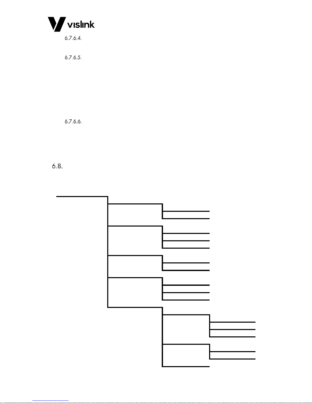
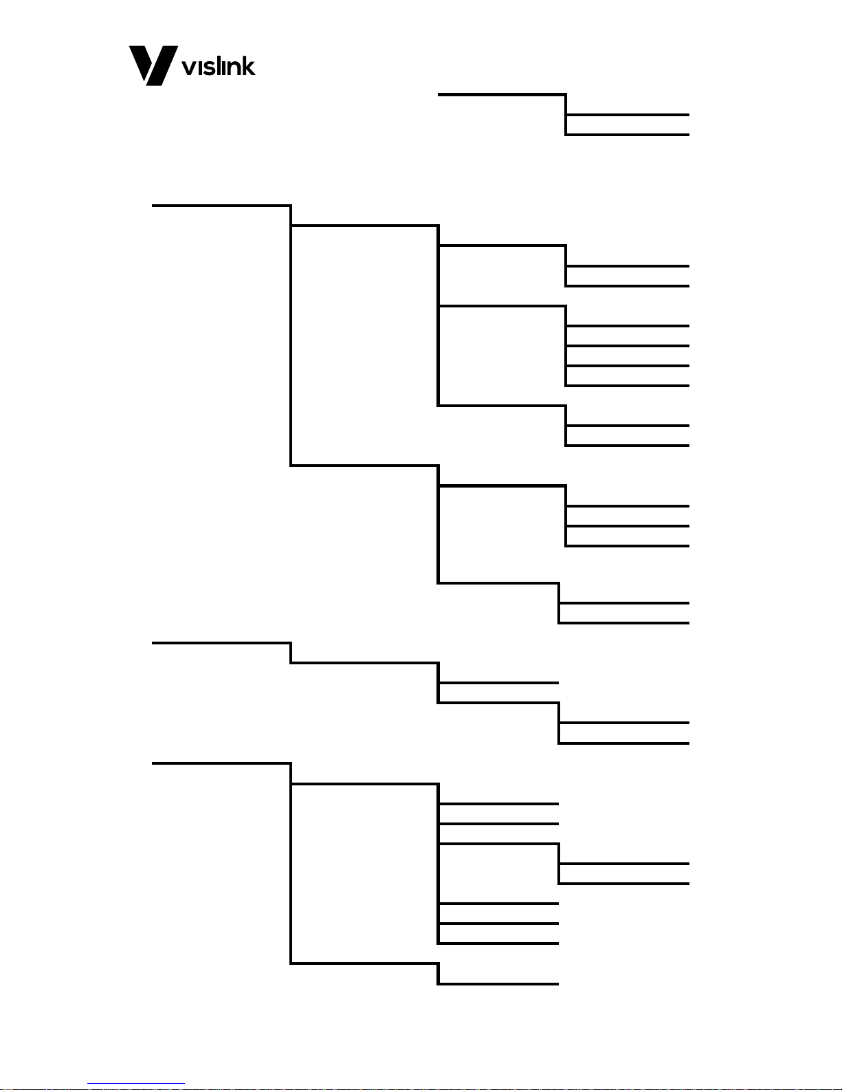
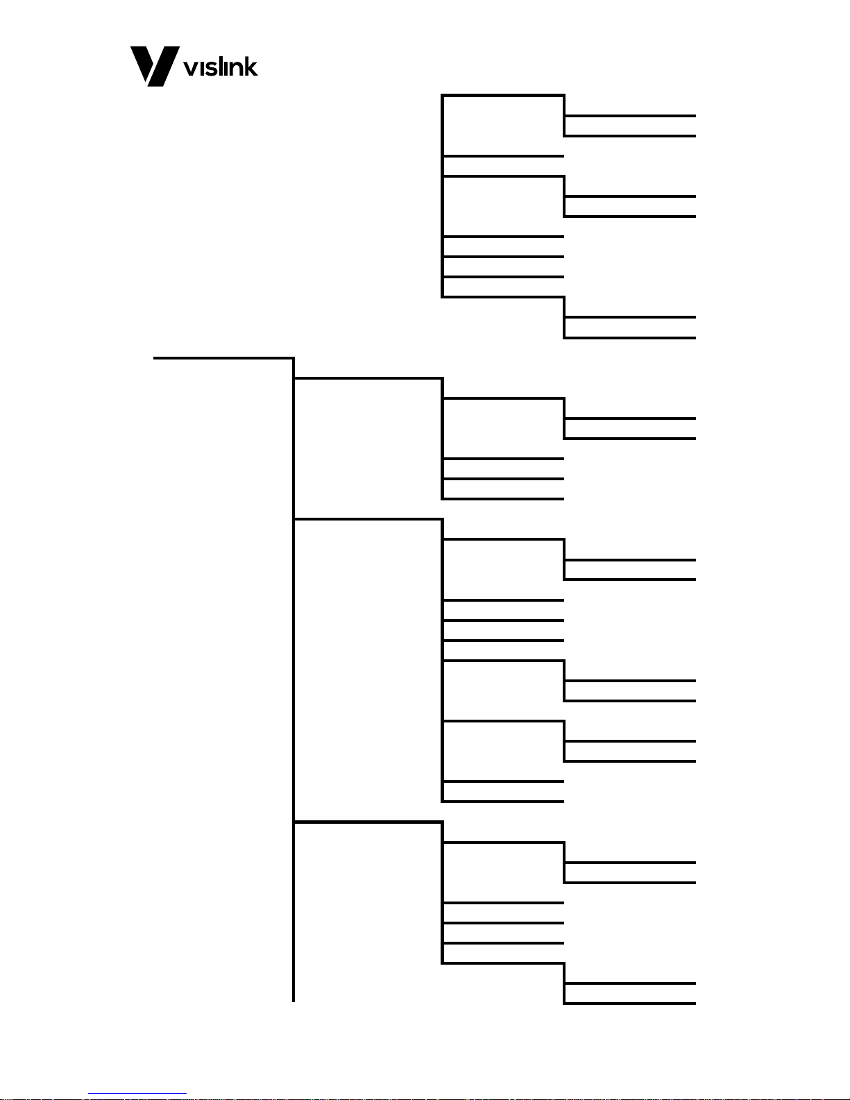
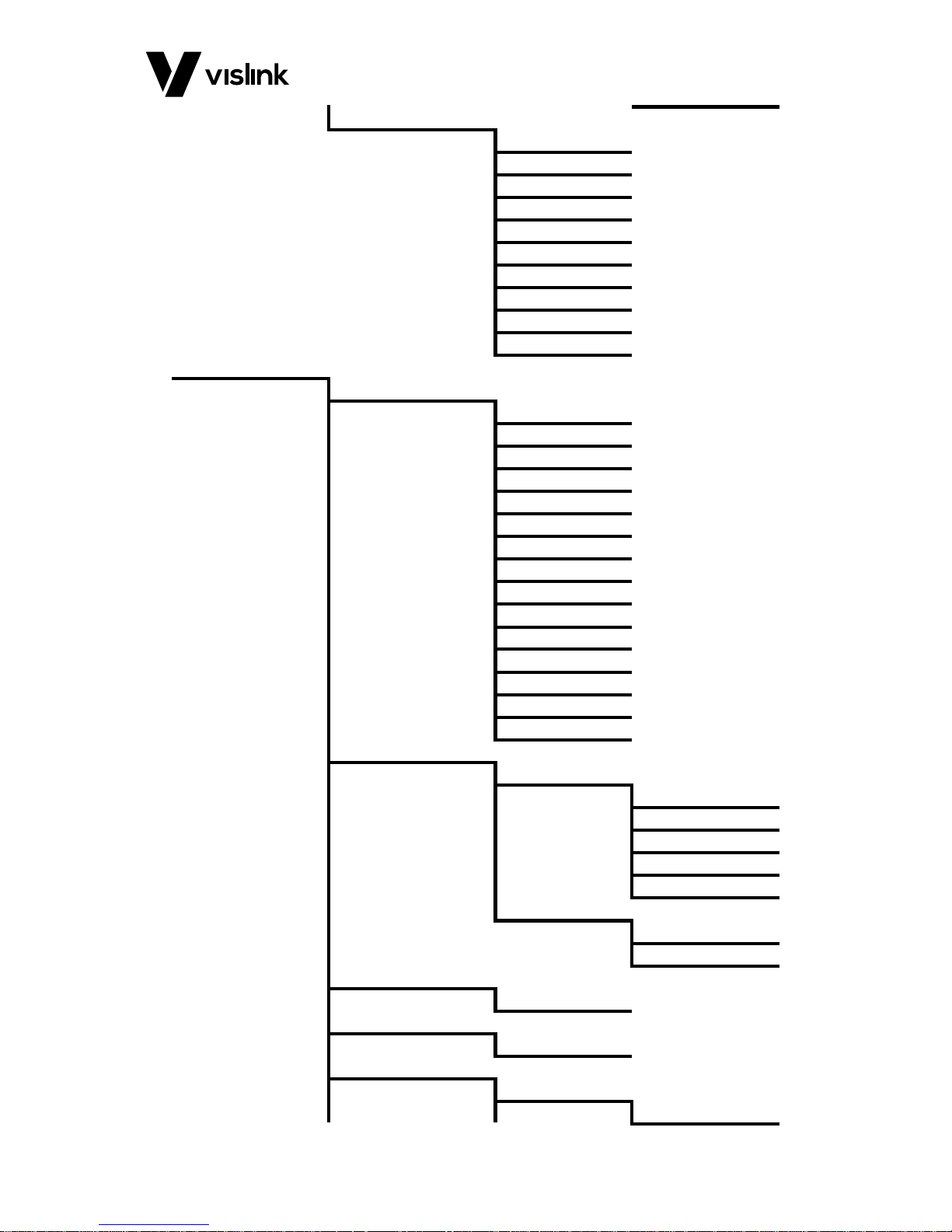
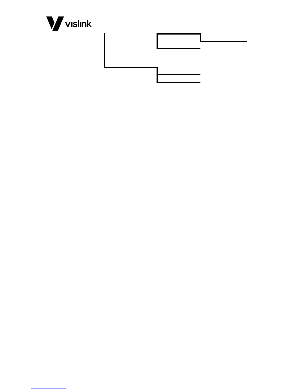
Receiver Menu Tree
NOTE: Items shown in green are only available in Advanced mode, and italicized items are
read only.
Channel/Frequency
Preset
Preset Name 1 to
Preset Name 16
Channel
Channel 1 to
Channel 16
Manual Channel
Preset Config
Preset Name 1 to
Preset Name 16
Channel Config
Manual Channel
Channel 1
Channel 16
Spectrum/Bandwidth
Bandwidth
6 MHz
7 MHz
8 MHz
Auto Spectrum
Disabled
Enabled
Spectrum
Page 30
RCD9 Receiver Operators Manual
Control Menus and Receiver Operation
Issue No: 1 Page: 24
Ref: RCD9-ASUM-7001 Copyright © 2017 IMT Ltd, trading as Vislink
Normal
Inverted
Inputs
Demodulator
RF Inputs
2-Input
4-Input
Diversity Mode
Input 1 Only
2-Way MRC
4-Way MRC
2x2 Switched
Triax Cards
Single Triax
Dual Triax
Decoder
ASI Input
Demodulator
Ext. ASI
Ext. IP
Signal Loss
Last Image
Blue Screen
Outputs
Analogue
A. Level Pair 1
A. Impedance
Low
600
Ports
User Data
PID
Format
Interface
RS232
RS485/422
Baud Rate
Parity
Data Bits
Ethernet
State
Page 31
RCD9 Receiver Operators Manual
Control Menus and Receiver Operation
Issue No: 1 Page: 25
Ref: RCD9-ASUM-7001 Copyright © 2017 IMT Ltd, trading as Vislink
Disabled
Enabled
MAC IP Allocation
DHCP
Manual
IP Address
Subnet Mask
Gateway
Allow SSH
Disabled
Enabled
ASI Over IP
Network Settings
IP Allocation
DHCP
Manual
IP Address
Subnet Mask
Gateway
ASI to IP
Protocol
RTP UDP
Dest. IP
Dest. UDP Port
Time To Live
Send Clear
Disabled
Enabled
FEC
Disabled
Enabled
FEC Columns
FEC Rows
IP to ASI
Address Method
Unicast
Multicast
Multicast IP
UDP Port
Delay
FEC
Disabled
Enabled
Page 32
RCD9 Receiver Operators Manual
Control Menus and Receiver Operation
Issue No: 1 Page: 26
Ref: RCD9-ASUM-7001 Copyright © 2017 IMT Ltd, trading as Vislink
Status
Mode
Dest. IP
ASI Input
Status
Protocol
Est. Bitrate
FEC Columns
FEC Rows
FEC Delay
Jitter Tolerance
General Settings
Software Versions
F.P. GUI
F.P. Kernel
Dmd. AVR
Dec. AVR
Dec. FPGA
Dec M.B. AVR
Triax AVR1
Triax AVR2
Triax AVR3
Triax AVR4
Head 1
Head 2
Head 3
Head 4
Display
Theme
Midnight
White Out
Purest Green
Gigawave
Purple Haze
Numbers
Wrap-around
Increment
Unit Name
Name
Temperatures
Decoder
Advanced Mode
State
Disabled
Page 33
RCD9 Receiver Operators Manual
Control Menus and Receiver Operation
Issue No: 1 Page: 27
Ref: RCD9-ASUM-7001 Copyright © 2017 IMT Ltd, trading as Vislink
Enabled
Change PIN
USB Upgrade
File Go
Page 34

RCD9 Receiver Operators Manual
Control Menus and Receiver Operation
Issue No: 1 Page: 28
Ref: RCD9-ASUM-7001 Copyright © 2017 IMT Ltd, trading as Vislink
This page is intentionally unused.
Page 35

RCD9 Receiver Operators Manual
Preparing for Operation
Issue No: 1 Page: 29
Ref: RCD9-ASUM-7001 Copyright © 2017 IMT Ltd, trading as Vislink
7. Preparing for Operation
Equipment Operation
Before leaving the equipment base to undertake an operation it is recommended that the
following equipment checks be made.
MVL HD3 Diversity Receiver
7.2.1. Antennas
The MVL-HD3 Diversity Receiver can be used with a variety of Gigawave antennas
FBA fan-beam antennas are used for wireless camera and on-board reception, or
when 4 are used in combination for 360 degrees ENG central city receive sites or
helicopter downlink reception. Fan beam antennas offer increased gain and
90-degree sector coverage.
HX series Helix antennas are circularly polarized antennas with increased directivity
and gain.
CO series Colinear antennas are used for Omni reception.
PA series Low profile antennas are used for up-linking ground to air, or on-board
linking.
Parabolic antennas offer the highest gain, and longest operation range.
Full details are given in the Gigawave Antennas data sheet.
7.2.2. Checks
We recommend completing the following minimum checks in the workshop, before you
leave for the filming site.
The receiver may be powered from 100/240VAC or DC PSU or by batteries.
Check that any batteries to be used are fully charged and that an emergency spare
battery is available and fully charged.
Confirm the correct frequency is selected (see Section 6.7.1).
Confirm that the correct digital outputs are selected, SDI or ASI (see Section 6.7.3.2).
Confirm the correct Analogue Audio level is selected (see Section 6.7.3.1.1).
Check that the Video, audio, DC and RF cables are in good condition.
Ensure that suitable keys are programmed into the unit.
NOTE: If the OSD is displaying a key number then decryption is not possible as the keys
stored in the unit do not allow access, or are missing.
Transmitter/Receiver Tests
Whenever practical, set up the system and trial it before leaving for site to ensure that all
components of the system are working. Checking at base, where adjustments and
corrective actions can be made, will pay off when setting up at site.
Page 36

RCD9 Receiver Operators Manual
Preparing for Operation
Issue No: 1 Page: 30
Ref: RCD9-ASUM-7001 Copyright © 2017 IMT Ltd, trading as Vislink
This page is intentionally unused.
Page 37
RCD9 Receiver Operators Manual
DVB-T Non-Hierarchical Bit-Rates
Issue No: 1 Page: 31
Ref: RCD9-ASUM-7001 Copyright © 2017 IMT Ltd, trading as Vislink
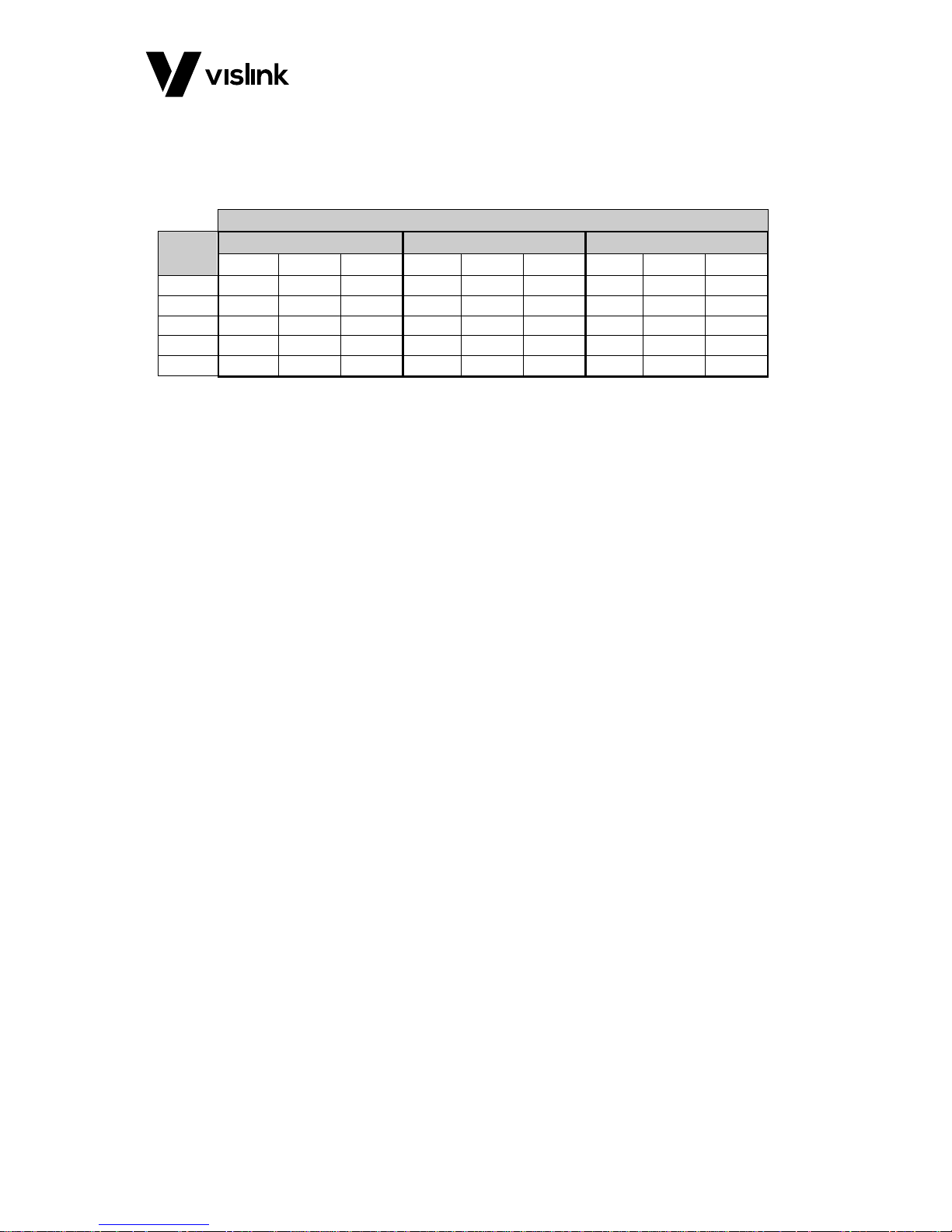
Appendix A DVB-T Non-Hierarchical Bit-Rates
A.1. DVB-T Bit Rates for 6, 7 & 8MHz
Guard Interval
Code
Rate
1/32
1/8
1/4
QPSK
16QAM
64QAM
QPSK
16QAM
64QAM
QPSK
16QAM
64QAM
1/2
4.52
9.08
13.57
4.14
8.29
12.44
3.73
7.46
11.19
2/3
6.03
12.06
18.08
5.52
11.05
16.58
4.97
9.95
14.92
3/4
6.78
13.57
20.35
6.22
12.44
18.66
5.59
11.19
16.79
5/6
7.54
15.08
22.62
6.91
13.82
20.73
6.22
12.44
18.66
7/8
7.91
15.83
23.75
7.25
14.51
21.77
6.53
13.06
19.59
Table A-1 DVB-T Bit Rates for 6, 7 & 8MHz
Page 38

RCD9 Receiver Operators Manual
Glossary of Terms
Issue No: 1 Page: 32
Ref: RCD9-ASUM-7001 Copyright © 2017 IMT Ltd, trading as Vislink
Appendix B Glossary of Terms
Item
Description
ADC
Analogue to Digital converter
AES3/EBU
Audio Engineering Society/European Broadcast Union – Standard for two channel
digital audio
ASI
Asynchronous Serial Interface, used for MPEG transmission
BER
Bit Error Rate
BNC
A medium sized RF/Video connector
C
Component Video – Chroma used as YC video format
C/N
Carrier to Noise ratio
COFDM
Coded Orthogonal Frequency Division Multiplex – a type of RF modulation
CPLD
Complex Programmable Logic device
CVBS
Analogue Composite Video, Blanking & Sync - PAL/NTSC
DAC
Digital to Analogue converter
DVB-T
COFDM modulation according to the international specifications of DVB
FPGA
Field Programmable Gate Array - A complex programmable Integrated circuit
GaAsFET
Gallium Arsenide Field Effect Transistor, a device used for RF amplification
I2C
Inter Integrated Circuit – Two wire (Clock & Data) interface
LCD
Liquid Crystal Display - Alphanumeric panel display
LED
Light Emitting Diode panel indicator
LVDS
Low Voltage Differential Signaling – high speed parallel digital interface
MER
Modulation Error Ratio
MRC
Maximum Ratio Combining (diversity reception)
Mux
Multiplexer
OCP
The Operator’s Control Panel
OSD
On Screen Display
PA
Power Amplifier
PCB
Printed Circuit Board
PID
Packet Identifier – MPEG data packet
PSU
Power Supply Unit
QAM
Quadrature Amplitude Modulation
QPSK
Quadrature Phase Shift Keying
RS
Reed Solomon – form of error correction
RS232
A standard data communications format
RS485
A standard data communications format
SDI
Serial Digital Interface
SMA
A small RF connector
SMB
A small RF connector
S/N
Signal to Noise Ratio
SPI
Synchronous Parallel Interface
TS
Transport Stream
VCO
Voltage Controlled Oscillator
XLR 3
An audio connector, the number indicates the number of pins
YC
Component Video – Luma and Chroma - YC video format
YUV
Component analogue video, Luma and Difference Signals
Table B-1 Glossary of Terms
 Loading...