

Visium AFD30CAT-4 Configuration & Installation Instructions
Installation Notes
Date ______________ Serial #______________________
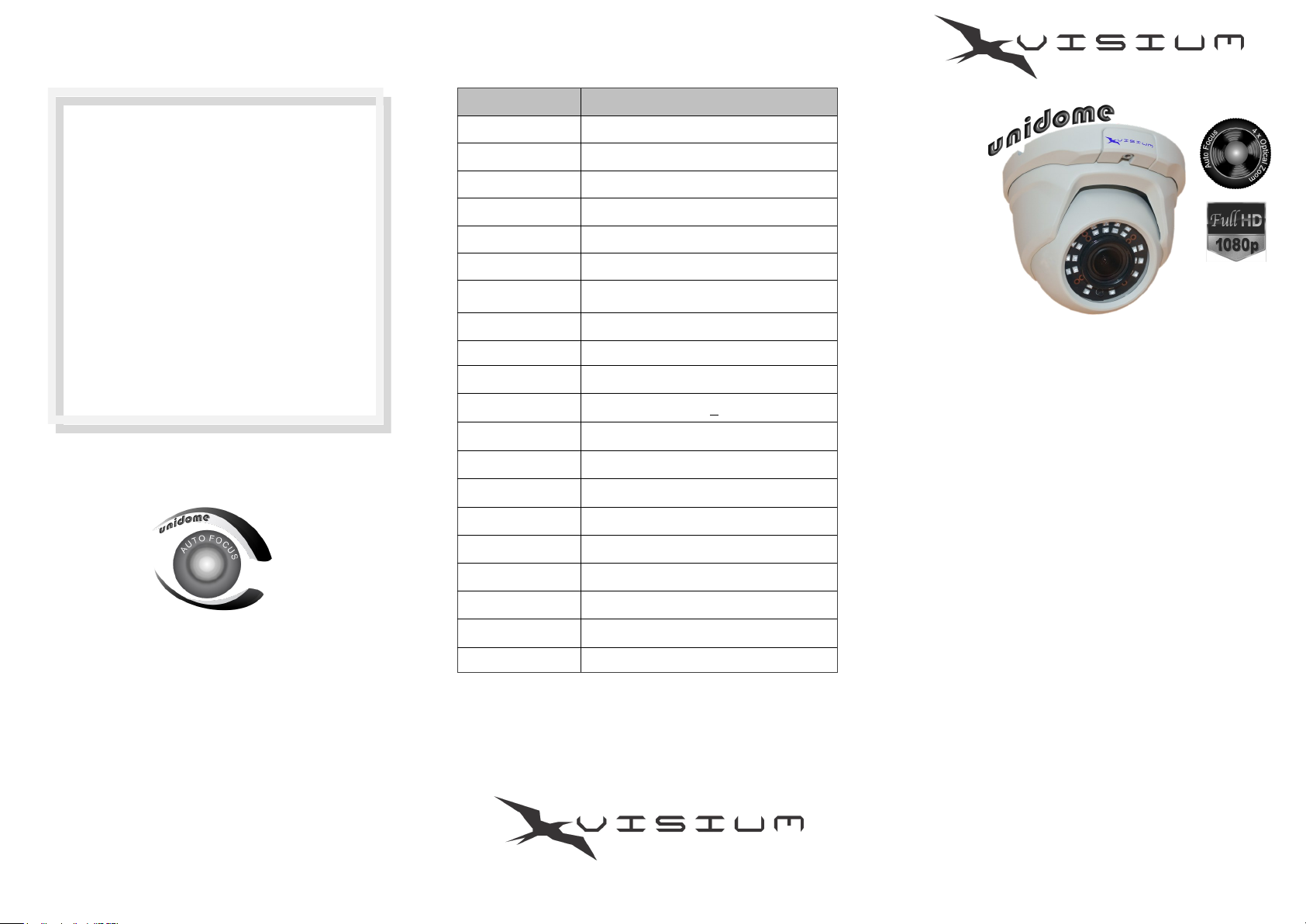
Specifications
Model AFD30CAT-4
Image Sensor 1/2.9” HDIS Sony IMX 323
Video Format NTSC
Resolution 1080P, 2.19Mp (Active Pixels 1985x1105)
Min Illuminance .01 (IR OFF) 0 Lux (IR ON)
S/N Ratio >48dB (minimum AGC gain)
Frame Rate 30fps (1080P)
AGC Auto
White Balance AWB
DNR 2D-DNR
D/N Auto. Color & B/W Controlled by CDS
Voltage/Current
12 VDC 400mA + 10% (IR ON)*
®
Model: AFD30CAT-4
Auto Focus Motorized Zoom
Infra Red CCTV Camera
Installation must comply with local, state and National laws. Install
according to local and NEC codes.
Any reproduction of this material by any means, in whole or in part is
prohibited without written permission of America’s Security Products LLC. ©
AF HD Lens
IR SMD LED (24)
IR Range Up to 98 ft/ 30 M (approximately)
Sync. System Internal
Video Output TVI / AHD / CVI / Analog (75Ω BNC)
Operating Temp. -4°~113° F (-10°~45° C)
Storage Temp. -4°~140° F (-10°~60° C)
Dimensions 4.50 (H) x 5.70 (Ø) (inch)
Weight 1.70 lb
*Amperage increases up to 200mA when
HD Motorized zoom, 2.8-12 mm*
Product Features
the ZOOM function is in use.
Full HD 1080P, SMD IR Night Vision
Multiple Configurable Video Outputs
Specifications subject to change without notice.
TVI / AHD / CVI or Analog
Day and Night Operation, IR Cut Filter
®
HD AF Motorized Zoom lens, 2.8-12 mm
AGC, AWB, 2D-DNR
Rugged Aluminum body, weather proof, IP66
WWW.VISIUM-USA.COM
Product made in China, documentation designed in the USA.
WWW.VISIUM-USA.COM
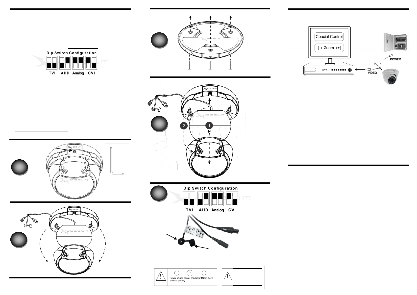
Configuration & Installation Instructions
This camera is compatible with most TVI,AHD,CVI &
Analog DVR’s. Please follow the below instructions to
set the appropriate video output. (See Fig.1) Remove the
dip switch Cap and select the appropriate settings based
on the below configuration. Replace Cap.
ON
OFF
1.Determine the appropriate location to mount the camera.
2.To separate the base from the camera body loosen the
screw (See Fig. A) with the tool provided with this
product.
3.Separate the base from the camera body (See Fig. B)
4.Install the base (See Fig. C) in the desired location.
5.Reassemble the camera components, (See Fig. D)
connect the video and power cables, aim the camera until
the desired image is seen on the monitor.
tighten the screw. Fig. A.
Screw
C
D
Typical Connection
The motorized zoom function is achieved via the
same coaxial cable in which the video is transmitted
using the DVR’s Coaxial Control Function.
We recommend that you confirm the compatibility of
your DVR prior to the installation.
IMPORTANT NOTE
Motorized zoom function increases the AMPERAGE
consumption up to 200mA momentarily while in use.
A
B
Tool
MAN-EN AFD30CAT-4 R.111517
1
Dip switches
Cap
USE ONLY 12 VDC REGULATED POWER
12 VDC 1.0 Amp
UL regulated Power
Supply
recommended
Precautions for use
1. This camera should only be installed by qualified
personnel.
2. Connect only to a regulated 12VDC UL approved
power supply, Center is (+).
3. Avoid installing near electric motors, cooling or
or heating systems, or any other electronic devise
that could generate static noise.
4. Do not use abrasives materials or detergents to
clean the lens.
5. Do not aim the camera at the sun or other
extremely bright objects. Extremely bright
objects will cause damage to this camera whether
powered or not.
6. Any modifications whatsoever or opening the
product will void all warranties.
WWW.VISIUM-USA.COM
 Loading...