

VISIPORT DiscAir TURBO DA175T Operating Instructions Manual
DiscAir
™
TURBO
Model DA175T
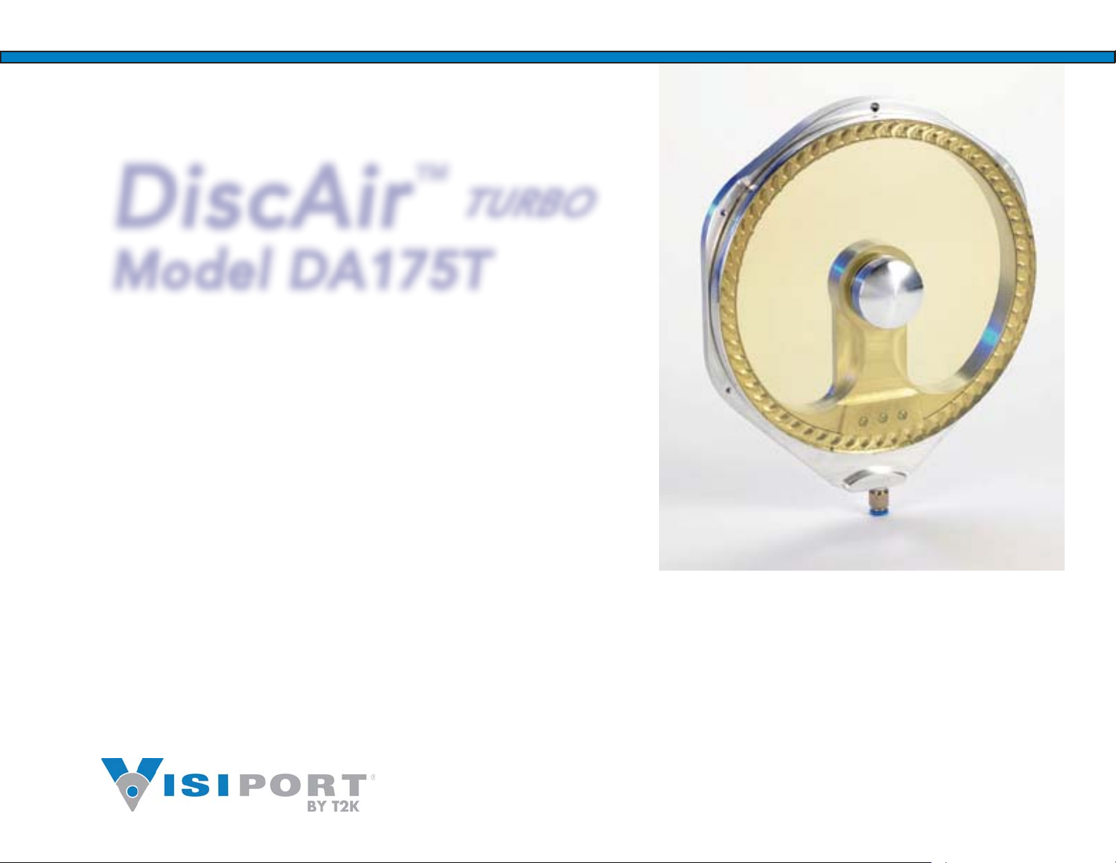
DiscAir
Model DA175T
Operating Instructions
Bedienungsanweisung
.使用説明書
TURBO

Table of Contents
Section
0.0 ...................................... Table of Contents
1.0 ...................................... Pre-Installation Instructions
1.1 ...................................... Parts and Equipment List
1.2 ...................................... Before You Begin Assembly
1.3 ...................................... Safety Information
1.4 ...................................... Warranty Information
2.0 ...................................... Mounting of Units
2.1 ...................................... Window Substrates
2.2 ...................................... Surface Preparation
2.3 ...................................... Preparing Installation Layout
2.4 ...................................... Standard Bonding Method (Code V)
2.5 ...................................... Bolt-on Method (Code D)
3.0 ...................................... Connections for Air
3.1 ...................................... Air Hookup
3.2 ...................................... Installing the Manifold
3.3 ...................................... Air Consumption
4.0 ...................................... Operation and Maintenance
4.1 ...................................... Operating Principle
4.2 ...................................... Maintenance and Troubleshooting
4.3 ...................................... Replacement Parts
4.4 ...................................... Customer Support
DiscAir DA175T
Section 1 Pre-Installation Instructions
This section covers the following topics:
Parts and Equipment List
»
Before You Begin Assembly
»
Safety Information
»
Warranty Information
»
Section 1.1, Parts and Equipment List
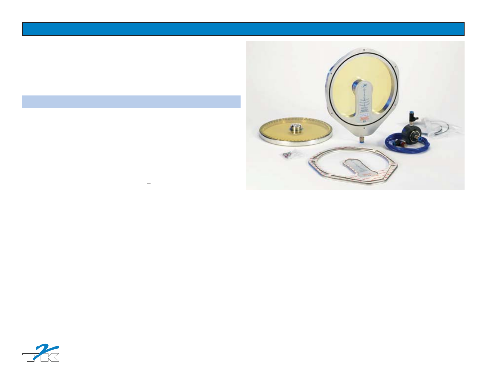
Unpack all DiscAir components carefully and verify that you have the following items:
DiscAir base assembly
1.
DLC (Diamond-like carbon) coated spin disc (disc/drive assembly).
2.
Standard VHB Mounting plate with O-ring (Units with DA175T.V designation)
3.
For transport, the Mounting Plate is lightly attached to the base assembly with screws.
After unpacking, dispose of these screws. For the fi nal attachment of the base assembly to
the Mounting Plate, please use the provided nylon-coated screws (see Item 7).
(This part is not if you order units with the DA175T.D Bolt-on designation.)
PVC Manifold with on/off valve (Units with DA.175T.H designation)
4.
Pressure regulator (pre-installed and adjusted into base assembly)
5.
Flexible polyurethane tubing, 1.0-meter (longer lengths available)
6.
Tool kit & small parts bag including L-Key wrench, silicone sealant, nylon-coated screws
7.
Installation Vacuum Pump (purchased separately as P/N 2209001)
8.
(For replacement part numbers and desciptions, please refer to Section 4.)
DiscAir Turbo - Model DA175T

DiscAir Turbo - Model DA175T
Section 1.2, Before You Begin Assembly
Before beginning the installation of this product, please read this manual. The DiscAir installation
process is straight forward. Determine the best location on the machine for the spin window and
manifold. Careful attention to instruction details will ensure a successful installation and many
hours of trouble free operation. Almost all installation problems result from the following:
Failure to adequately clean the window surface to receive the DiscAir installation.
1.
Failure to replace used, contaminated polycarbonate windows for DiscAir installation.
2.
Contamination of the bonding set adhesive from fi ngerprints or premature exposure of VHB.
3.
Attempts to install DiscAir on “siliconized” or hard coated polycarbonate windows.
4.
Failure to apply silicon rubber around the DiscAir base.
5.
Machine tool windows that are not fl at or rigidly mounted into the enclosure.
6.
For additional information or clarifi cation of these instructions, or for assistance with any aspect of
your Discair spin window system, please contact T2K or your vendor.
Section 1.3, Safety Information
The DiscAir Turbo Model DA175T is designed to be mounted on a windows of machine tools
1.
with fully enclosed work area where metalworking fl uids are used for lubrication.
DiscAir units rotate at up to 4.000 rpm. Even after turning off the air supply, the Disc/Drive
2.
Assembly (spin disc) will rotate for some time.
Turn off air supply to the spin window when performing service or entering the machine
3.
cabin. Do not touch or otherwise allow any body contact with the spin disc until rotation has
ceased. Wear eye protection at all times when exposed to rotating spin disc.
Never operate the DiscAir without the spin disc installed, as this exposes underlying Bearing
4.
Assembly to metalworking fl uids that may lead to premature destruction of the bearings.
Do not install a DiscAir spin window into a cutout unless the spin window has been bonded
5.
to a substrate at T2K.
Replace all spin discs that have been chipped, struck, cracked, dropped, or damaged in any
6.
way. This includes spin discs that show signs of etched metal from acidic or corrosive coolant
and disc glass which exhibits unusual wear from chip bombardment. Do not operate the
DiscAir until a new spin disc has been installed.
Warning: The regulator at the bottom of the unit has been pre-adjusted. For safety reasons
7.
this setting must not be changed!
Spin windows augment safety programs! Without the viewing benefi ts of spin windows, a
8.
machine operator may be tempted to bypass the machine tool interlock to get a look inside
a machine cabin. Be safe. Install spin windows.

DiscAir Turbo - Model DA175T
Section 1.4, Warranty Information
DiscAir components are warranted to be free from defects in materials and workmanship for six
months. Components which fail within this period of time will be replaced without charge.
Abrasion to the spin disc is not covered by this warranty, nor is any other damage to the glass
subsequent to its intact arrival due to drops, tool impacts, or other events arising from normal
operation or mishandling.
Diamond-Like-Carbon (DLC) coated glass discs are much more resistant to scratching from chip
activity than those made from standard uncoated chemically strengthened fl oat glass, but it is not
any more resistant to breakage from impacts due to droppage or projectiles.
Failure of components from misuse, improper air supply pressure or hookup, or failure to observe
the restrictions set forth in these Operating Instructions is not covered by warranty. Failure of parts
and/or components due to improper installation is not covered by warranty.
Freight costs for any items sent to T2K for warranty evaluation or repair is to be at customer’s cost.
A Returned-Goods-Authorization (RGA) number, issued by T2K, is required in order to return units
to T2K. Items sent to T2K without such an RGA will not be accepted. Decisions to cover parts and/
or components under warranty, and to replace or repair such parts is at the sole discretion of T2K.
 Loading...