

Page 1

r
VS4500
Wireless Time & Voice Controlle
User's Manual / Installation Guide
Version 1.14
Visiplex, Inc. 2018
Page 2

VS4500
Wireless Time & Voice Controller
Copyright
The product described in this manual includes copyrighted Visiplex computer programs stored in
semiconductor memories and computer files. As such, these programs may not be copied or
reproduced in any manner without the express written permission of Visiplex, Inc.
Disclaimer
The information within this document has been carefully checked and is believed to be entirely
reliable. However, no responsibility is assumed for inaccuracies. Visiplex, Inc. reserves the right to
make changes to any of the products herein to improve reliability, functional ity or design.
Copyright ©Visiplex, Inc. Buffalo Grove, IL 2018
Notice to User Regarding Radio Frequency Interference
This equipment has been tested and found to comply with the limits for a Class A digital device
pursuant to Part 15 of the FCC Rules. These limits are designed to provide reasonable protection
against harmful interference when the equipment is operated in a commercial environment. This
equipment generates, uses, and can radiate radio frequency energy and, if not installed and used
in accordance with the instruction manual, may cause harmful interference to radio
communications. Operation of this equipment in a residential area is likely to cause harmful
interference in which case the user will be required to correct the interference at his own expense.
About This Manual
This VS4500 User’s Manual / Installation Guide describes the installation and setup procedures of
the VS4500 for wireless messaging. It also provides instructions for transmitter antenna
installation.
It is imperative the manual is followed in the order it is presented to prevent damage to the
equipment, as well as insuring proper system functionality.
The manual provides instructions for mounting preparation, determining system location and
spacing in regard to antennas and other equipment. Information is also provided for verification of
reception and transmission quality and troubleshooting of problems that may arise during
installation or operation.
2
Page 3

Table of Contents
Product Information
1.1 Introduction 5
1.2 Standard Features 6
1.3 Optional Features 6
1.4 Package Contents 6
1.5 Key Navigation 6
1.6 Display Indicators 6
1.7 Pre-Installation Test for Wireless Clocks 7
Installation
2.1 Site Inspection and System Location 8
2.2 GPS Receiver Installation (optional) 8
2.3 Magnetic Mount Antenna (VS638) Installation 8
2.4 Base Station Outdoor Antenna Kit (VS654) Installation 8
2.5 VS4500 Encoder and External Transmitter Installation 9
Advanced System Information
3.1 Administration Menu 10
3.1.1 Device Database Menu 10
3.1.2 Time Setup Menu 11
3.1.3 Date Setup Menu 11
3.1.4 View Messages Menu 11
3.1.5 Coverage Test Menu 12
3.1.6 Time Zone Setup Menu 12
3.1.7 Last Messages Menu 12
3.1.8 Reset Database Menu 12
3.1.9 Sunset / Sunrise Menu 13
3.1.10 Wireless Setup Menu 13
3.1.11 Operation Modes Menu 15
3.1.12 System Setup Menu 16
3.2 Installation Mode Menu 17
3.3 Page To Menu 18
3.4 Accessing Wireless Receivers via Telephone 18
3.4.1 Accessing Standard Devices 18
3.4.2 Accessing Wireless Voice or Tone Receivers 18
3.5 Accessing Wireless Voice Receivers via Microphone 19
3.6 Initiating and Answering Intercom Calls 19
3.7 Background Music (FM Radio) Setup on Wireless Amplifiers 20
3.8 Pre-Programmed Messages 21
3.8.1 PABX Messages 21
3.8.2 FreeText 21
3.8.3 Wireless Devices 22
3.8.4 Voice Messages 22
Software
4.1 VPS 24
4.1.1 Connections 24
4.1.2 Software Installation 24
4.1.3 Software Configuration 24
4.1.4 Setting Date and Time from PC 25
4.1.5 Weekly Tone & Bell Schedule 25
3
Page 4

4.1.6 Calendar Tone & Bell Schedule 27
4.1.7 Scheduled Paging Activation 32
4.1.8 System Devices Database Programmer 34
4.2 TimeSync 34
4.2.1 Connections 35
4.2.2 Software Installation 35
4.2.3 Software Configuration 35
4.2.4 Setting the PC Clock from Encoder 36
4.2.5 Setting the Encoder Clock from PC Clock 36
Appendices
5.1 Appendix A – Installation Diagrams 38
5.2 Appendix B – Connections, Wiring and Pin Out 40
General Information
6.1 Specifications 42
6.2 Warranty 43
4
Page 5
Product Information
1.1 Introduction
capable of addressing up to 1000 receivers. It consists of a fully featured encoder with a 2 line by 16-character LCD display
and a numeric keypad mounted in a wall or desk mountable housing.
The VS4500 is compatible with the Visiplex series of digital transmitters ranging from 6 to 300 watts. An internal 6 watt
transmitter can be installed at the factory and larger transmitters are available as separate items.
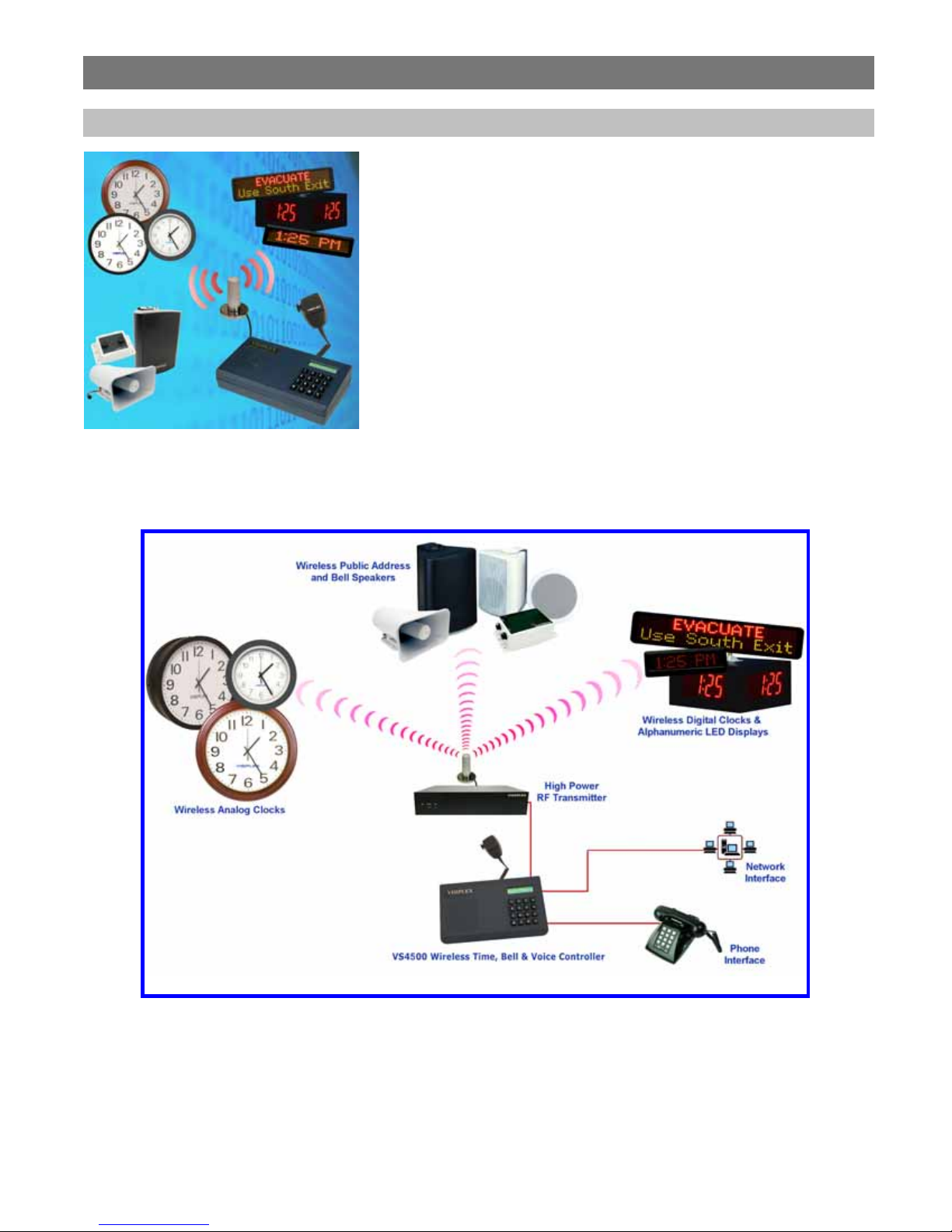
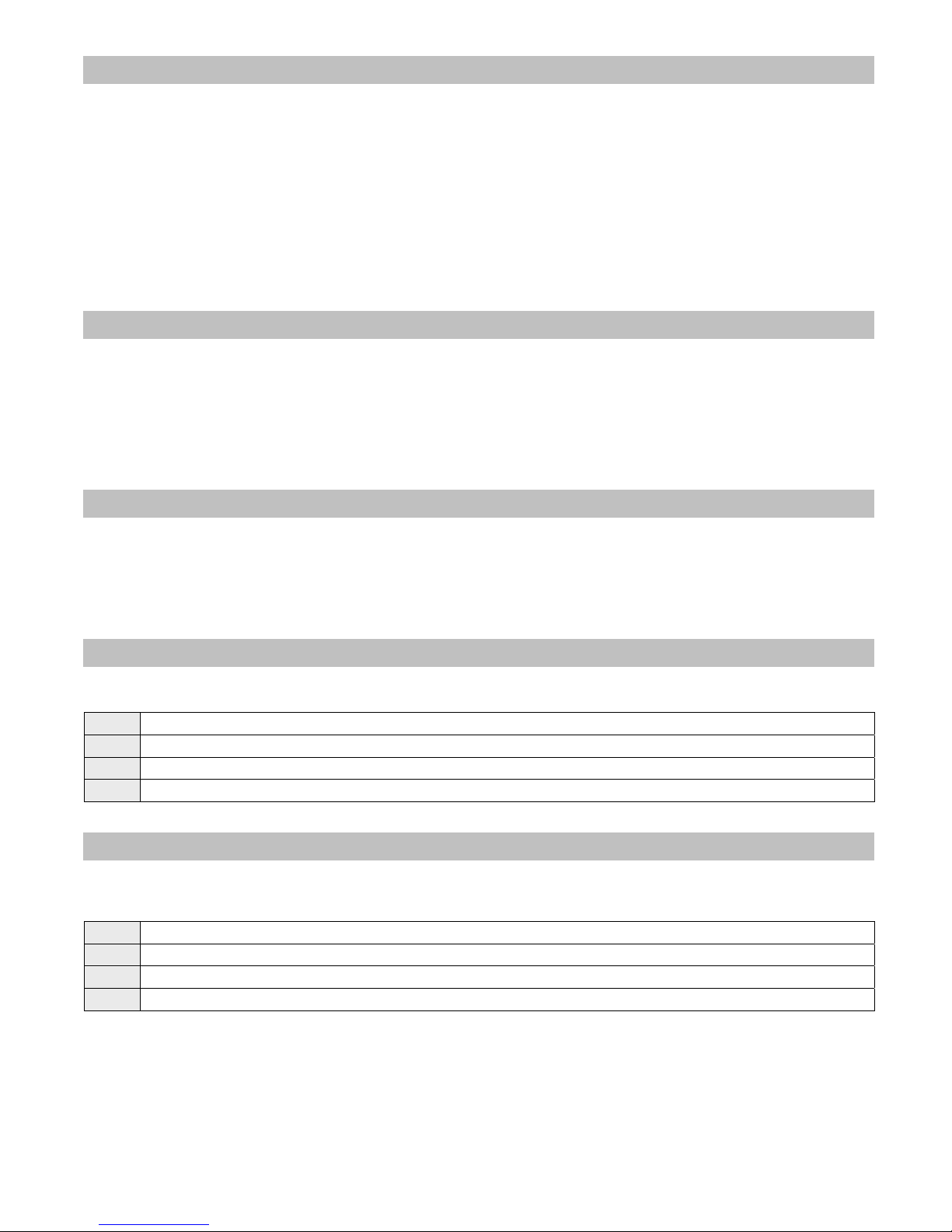
The VS4500 offers the latest and most innovative way to incorporate PC clock
or GPS synchronized time, voice and data throughout your facility, providing
you with the benefits of improved productivity and reduced maintenance costs.
The VS4500 wireless controller is a sophisticated time, bell and voice
management system that can synchronize all facility wireless clocks to one
accurate atomic time, run a schedule of bells/alerts, initiate live or prerecorded voice messages and send alphanumeric messages to LED displays.
Additional features of the VS4500 include an optional PBX interface and
optional hand held microphone.
The VS4500 uses the PC clock as a time source for wireless analog clocks,
wireless digital clocks and wireless alphanumer ic d isp lays. The VS45 00 ca n also
be used to synchronize older wired clocks using a special wireless rece iver.
Using the connected PC clock or GPS receiver, the VS4500 updates its internal
clock every few minutes and sends a wireless data signal every minute to
provide time synchronization information to all system clocks.
The VS4500 is a powerful microprocessor-based desktop paging system
5
Page 6
1.2 Standard Features
• Generate alerts to alphanumeric and numeric devices, voice or tone devices, and wireless clocks
• User configurable 1000 devices database
• RS232 serial port for serial communication
• Built-in high-precision Real-Time clock
• Capable of synchronizing its internal clock from a PC clock or GPS (requires external GPS receiver)
• Synchronize both analog and digital wireless clocks
• User configurable Master Clock synchronization time
• External transmitter port
• Backlit LCD display
• Numeric keypad
• Built-in memory backup
• Desk or wall mountable
1.3 Optional Features
• Telephone line interface (RJ-11) for remote status change of system mode and live voice alerts
• Hand held microphone for live voice alerts
• Additional one serial port for extended serial communication
• Built-in scheduled tone activation for wireless receivers
• High power external digital transmitters (25 to 300 watt)
• Automated activation of wireless voice devices from exter nal audio source
• 900MHz or UHF Wireless receiver for monitoring 900MHz or UHF wireless push buttons and transmitters
1.4 Package Contents
The following items are included with the VS4500:
• VS4500 Wireless Time & Voice Controller
• Power adaptor
• Manual
• USB cable (Note: RS232 null-modem communication cable supplied prior to 04/01/2014)
1.5 Key Navigation
The following keys also function in system menus as detailed below:
# Select / Acknowledge / Enter
* Return to previous menu / Escape
1 On / Next
0 Off / Previous
1.6 Display Indicators
Time source reception status (displayed be tween the hour and minutes segmen ts) and daylight saving status (d isplayed to
the left of the hour segment) indicators are displayed on the main menu:
. No connection with time source
; No GPS or PC clock data reception detected
: GPS or PC clock data reception detected, date and time updated
* Daylight saving time is active
6
Page 7

1.7 Pre-Installation Test for Wireless Clocks
It is recommended to test the VS4500 and the entire system prior to installation in order to verify proper operation and get
familiar with the unit operation.
Follow these steps to perform a pre-installation test:
1. If your system is equipped with an i nternal transmitter, connect the BNC antenna cable to the RF-OUT terminal at the
back of the VS4500.
If your system uses an external transmitter, connect the transmitter data cable between the VS101-XX transmitter and
the DATA I/O port at the back of the VS4500. Connect the antenna to the external transmitter’s RF-OUT terminal.
2. Connect the provided power supply to the POWER jack at the back of the VS4500 and turn the power switch to ON
position. The main menu should appear with the PAGE TO: displayed on the top line.
If you are using an external transmitter, make sure it is powered on.
3. Press the B key for the Administration Menu and enter the default password (4500). The menu top line should display
SELECT OPTION:
4. Press 2 followed by the # key for the internal clock Time Setup. Enter the UTC (Universal Coordinate Time) or GMT
(Greenwich Mean Time) time in 24 hours (m ilitary) format. The display will change back to Time Setup.
5. Press 3 followed by the # key for the internal clock Dat e Setup. Enter the UTC (Universal Coordinate Time) or GM T
(Greenwich Mean Time) date in MMDDYY format. The display will change back to Date Setup.
6. Press 6 followed by the # key for the Time Zone Setup menu. Enter the offset in hours of the local time zone from UTC
(Universal Coordinate Time) or GMT (Greenwich Mean Time) time. Use 01 to 23 for negative offset (GMT -1 to GMT -23),
00 or 24 for GMT time, 25 to 47 for positive offset (GMT+1 to GMT+23).
The display will change back to Time Zone Setup.
7. Press A followed by the # key for the Wireless Setup menu. Press 3 for the Time Sync Mode menu followed by the #
key. Press 1 followed by the # key to enable time synchronization.
8.
Press the * key to return to the Main Menu.
9. Press C to start the transmission o f time synchronization every minute (installation mode).
Within a few minutes, the VS4500 will start sending the time information page every minu te. Set a clock to receive
signal and make sure it receives and displays the correct time as displayed on the VS4500 display.
7
Page 8

Installation
2.1 Site Inspection and System Location
Consider the following requirements when planning system installation and choosing a location for the VS4500 and other
system components:
1. If the optional GPS rec eiver is used, it should be installed where it is exposed to the sky, parallel to the horizon and
unobstructed by trees, power-lines, etc.
If the GPS receiver is installed indoors, mo unt it at the lower edge of a window, away from Low E glass and exposed to
the sky.
2. Choose a location that is easily accessible in case you need to perform maintenance on the antenna.
3. The transmitting antenna should b e located as close as po ssible to the center of the site and should not be surro unded
by large metal objects that may block the RF s ignal and decrease the coverage range of the system.
4. The transmitting antenna may be mounted vertically upward, NEVER horizontally.
5. Magnetic Mount antenna (such as VS638) should be attached to a large metal object (like an air duct, metal shelf or
cabinet) to provide it with a proper grounding. It may be mounted vertically upward or downward.
6. Base Station antenna (such as included with VS654 kit) should be secured to a well-grounded metal structure or to a
pole on the roof.
Locate a path for running the coax cable between the antenna and the transmitter such as a riser ( if there is no existing
path, create one).
Place the external transmitter in a location that is as close as possible to the roof such as in the penthouse. Keep the
distance between the antenna and the transmitter as short as possible to minimize RF power loss.
2.2 GPS Receiver Installation (optional)
1. The optional GPS receiver can be mounted indoors or outdoors. Outdoors insta llation is highly recommended for
optimal reception.
2. The GPS receiver should be installed where the distance to the VS4500 is not more than 100’.
3. If the GPS receiver is installed indoor (not recommended), mount it at the lower edge of a window, away from Low E
glass and exposed to the sky.
4. If the GPS receiver is installed outdoors, mount it in a location protected from direct sun or rain.
5. If the GPS receiv er is installed outdoors, secure it the structure or to the wall -mounting “L” bracket included with your system
that allows mounting of the antenna on the side of a building or other structure.
6. Connect the GPS receiver to the COM1 serial port and set the serial port to the required settings (see page 16 for more details).
2.3 Magnetic Mount Antenna (VS638) Installation
1. Secure the antenna to an adequate grounding surface, HVAC duct or metal “I” beam. The antenna should be mounted vertically
2. Choo se a mounting location that will provide an adequate grounding surface and free space fo r RF radiation. If the antenna is
3. The optional wall-mount “L” bracket allows mounting the magnetic antenna on the side of a building or other structure, providing
Note: The antenna should be located as far from the VS4500 and transm itter as the coax ca ble allows.
2.4 Base Station Outdoor Antenna Kit (VS654) Installation
1. To achieve maximum performa nce for your outdoor antenna choose a loca tion that is unobs tructed by trees, branches , power-
2. Choose a location that is easily accessible in case you need to perform maintenance on the antenna.
upward or downward, NEVER horizontally.
mounted too close to metal or closed heavy concrete walls room, a high VSWR may occur which in the long term may cause
damage to the transmitter.
the roof’s overhang is not excessive.
lines, etc. Never mount the antenna where there is a signal-reflecting surface such as metal, power lines, mirrored glass, etc.
8
Page 9

3. For optimal performance, make sure the ante nna is installed at an elevation that will provide suff icient clearance to allow your
antenna to radiate without interference.
4. It is recommended to mount the antenna where the path of the antenna cable is straight and as close as possible to the system
transmitter. Do not coil up 100 feet of coaxial cable when only 20 feet of cable is required. Use a RG-8U coax cable that is
specified as Low Loss to minimize power loss.
5. The antenna may be mounted vertically upward, NEVER horizontally.
6. Install the grounding kit provided with the VS654 antenna kit.
Note: The antenna should be located as far from the VS4500 and transm itter as the coax ca ble allows.
2.5 VS4500 Encoder and External Transmitter Installation
The VS4500 system encoder can be installed on a wall or shelf. Install a UPS power backup to protect the system from power
outages and surges. If you are using an external transmitter, place it next to the VS4500 and use the data cable provided to
connect VS4500 and the external transmitter.
Once the transmitter and antenna are placed properly, connect them to the VS4500 and the transmitter as follows:
1. If an external transmitter is used, connect the antenna to the RF-OUT terminal at the back of the external transmitter. Connect
the transmitter data cable between the VS101-XX transmit ter and the DATA I/O port at the bac k of the VS4500.
Otherwise, connect the antenna to the RF-OUT terminal at the back of the VS4500.
2. If the optional GPS receiver is used, the internal clock of the VS4500 will be set to the UTC time and the VS4500 will
start transmitting the local time ev ery minute.
3. If the PC time is used, connect the PC serial port to the COM1 terminal and run the TimeSync or VPS software. See
Setting Date and Time from PC section on page 25 or TimeSync section on page 34 for more detailed information.
4. No additional programming is needed for the system to be fully operational. See Advanced System Information
section on page 10 for more detailed information about the VS4500.
Note: Do not place the VS4500 on top of the external t ransmitter as RF fe edback may cause syste m malfunction.
9
Page 10

Advanced System Information
The main menu shown below appears after the VS4500 is turned on and is used for accessing the Programming and
Administration menus. This menu is also used for sending a page to a receiver.
PAGE TO: 11:55
3.1 Administration Menu
From the Main Menu press the B key. Enter 4500 as password. The prompt Select Option will appear on the top line.
The Administration Menu provides access to the following available sub-menus:
1. Device Database
2. Time Setup
3. Date Setup
4. View Messages
5. Coverage Test
6. Time Zone Setup
7. Last Message
8. Reset Database
9. Sunset/Sunrise
A. Wireless Setup
B. Operations Modes
C. System Setup
D. TX Test Tone
To access a specific sub-menu, press the digit key representing it.
3.1.1 Device Database Menu
From the Administration Menu, select 1 followed by the # key. Following are the fields description:
Device to Edit
Device Capcode
Device Type
Paging Mode
Group
Enter 3 digit ID of the programmed device (001-899).
If the device already exists, its details will be displayed for editing or deleting.
Group devices (01-99) are represented and accessed by paging to devices 901-999.
Enter the capcode of the programmed device. For Voice pagers, enter “0” followed by Tone A
and Tone B (for example, “0110111”).
Select the type of the programmed device.
0
- Alphanumeric Pager
1 - Numeric Pager
2 - Tone Only Pager
3 - Voice Pager
4 - Wireless Speaker
5 - Widearea Pager (Note: Optional modem is required)
6 - Portable Radio
7 - Phone
8 - LED Display
9 - Intercom Station
Select Mode and Baud Rate and press the # key:
1 – 512 bps, Mode 0
2 – 512 bps, Mode 1
3 - 512 bps, Mode 2
4 – 512 bps, Mode 3
5 – 1200 bps, Mode 0
6 – 1200 bps, Mode 1
7
- 1200 bps, Mode 2
8 – 1200 bps, Mode 3
9 – 2400 bps, Mode 1
0 – 2400 bps, Mode 2
If the device is a member in a group, enter the group number (0-99) and press t he # key.
Group devices are represented and accessed by paging to devices 901-999.
10
Page 11
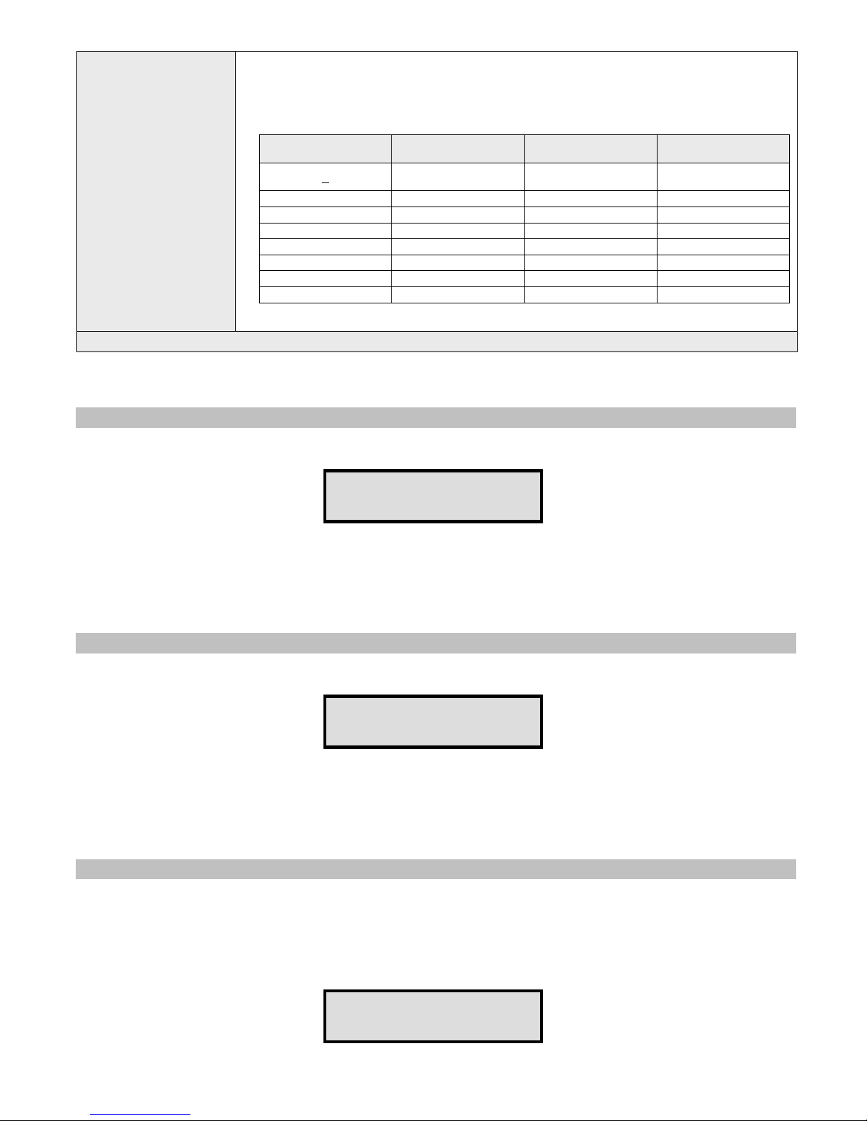
Additional device parameters:
1. For Widearea service pagers, it contains the 3-digit area code.
2. For Intercom devices, this field allows override of the Full-Duplex, Auto answer and
Incoming Alert Tone settings programmed in to the VNS22xx (applicable to VNS22xxversion
4.06 or later):
DSC Value
DSC
(Device Special
Command)
Note: Underlined values indicate default values.
After the last step is completed, the display will flash DATA SAVED and return to the Device to Edit menu.
Repeat the above steps for additional devices or press the * key twice to return to the Main Menu.
0
1 X - -
2 - X 3 X X X
4 - - 5 X - 6 - X 7 X X -
Full Duplex / Hand
Free
Default VNS22xx
Settings
Auto Answer
Default VNS22xx
Settings
Incoming Call Alert
Tone
Default VNS22xx
Settings
3.1.2 Time Setup Menu
From the Administration Menu, select 2 followed by the # key. The following screen will be displayed:
ENTER GMT TIME:
12:00
Enter the UTC (Universal Coordinate Time) or GMT (Greenwich Mean Time) time in 24 hours (military) format. The display
will change back to Time Setup.
DO NOT enter the local time as the u nit uses the universal ato mic time as a reference and cal culates the local time base d
on your Time Zone.
If the VS4500 is connected to a PC or receives the time from a GPS receiver, it will revert back to the source time few
minutes later overwriting the time changes made.
3.1.3 Date Setup Menu
From the Administration Menu, select 3 followed by the # key. The following screen will be displayed:
ENTER GMT DATE:
010106
Enter the UTC (Universal Coordinate Time) or GMT (Greenwich Mean T ime) date in MM DDYY format. The display will change
back to Date Setup.
DO NOT enter the local date as the unit uses the univers al atomic time as a refere nce and calculates the lo cal time based
on your Time Zone.
If the VS4500 is connected to a PC or receives the time from a GPS receiver, it will revert back to the source time few
minutes later overwriting the time changes made.
3.1.4 View Messages Menu
Use this option to view the pre-programmed messages. Pre-programmed messages allow you to send alphanumeric
message via the keypad or optional telephone interface by entering * followed by the message number.
For example, if message 05 is programmed as “TEST”, entering *05 will send the message “TEST” to the selected device.
See Page to Menu section on page 18 for more detailed information.
From the Administration Menu, select 4 followed by the # key. The following screen will be displayed:
PPGM MESSAGE: 01
11
Page 12

Use the A & B key to navigate through the pre-programmed messages.
Press the * key to return to the Administration Menu.
3.1.5 Coverage Test Menu
From the Administration Menu, select 5 followed by the # key. Enter a value between 1 and 8 to determine the cover
page interval:
1 – Every 5 seconds
2– Every 10 seconds
3 – Every 15 seconds
4 – Every 20 seconds
5 – Every 30 seconds
6 – Every 1 minute
7 – Every 2 minutes
8 – Every 4 minutes
Use this option to send cover page to device 100. This feature is useful when testing the transmitter coverage area.
Press * to cancel and return to the Administration Menu.
3.1.6 Time Zone Setup Menu
From the Administration Menu, select 6 followed by the # key. The following screen will be displayed:
TIME ZONE SETUP:
06
Enter the offset in hours of the loca l time zone from UTC (Universal Coordinate Time) or GMT (Greenwich Mean Time) time.
Use 01 to 23 for negative offset (GMT -1 to GMT -23), 00 or 24 for GMT time, 25 to 47 for positive offset (GMT+1 to
GMT+23).
For examples, for the following time zones, enter the following values:
Eastern Time: 05
Central Time: 06
Mountain Time: 07
Pacific Time: 08
Alaska Time: 09
Hawaii Time: 10
After the last step is completed, the display will return to the Administration Menu.
3.1.7 Last Message Menu
From the Administration Menu, select 7 followed by the # key.
Use this option to display the las t message sent to a device.
Press * to cancel and return to the Administration Menu.
3.1.8 Reset Database Menu
NOTE
: This is an IRREVERSIBLE command - DO NOT select th is option unless y ou are absolutely s ure you want to cl ear
all devices and pre-programmed messages data.
You may want to transcribe this information to paper first or use the optional PC software to backup the data to a computer.
From the Administration Menu, select 8 followed by the # key.
CLEAR ALL DATA..
ARE YOU SURE???
Press # to confirm the Database Reset. Press * or any other key to cancel and return to the Administration Menu.
12
Page 13
3.1.9 Sunset / Sunrise Menu
Use this option to display the current settings for sunset and sunrise.
From the Administration Menu, select 9 followed by the # key. The following screen will be displayed:
SUNSET/SUNRISE:
R06:22 S17:43
Following is the description of the displayed information:
R: Sunrise time as indicated by the following 5 characters
S: Sunset time as indicated by the following 5 characters
Press the * key to return to the Administration Menu.
3.1.10 Wireless Setup Menu
From the Administration Menu, select A followed by the # key. The following screen will be displayed:
WIRELESS SETUP:
PA VOLUME
This screen allows the administrator to configure different wireless settings of the VS4500.
Press the key representing the field followed by # key to edit the settings. Following are the fields description:
1 - PA Volume
2 - PA Timeout
3 - Time Sync Mode
4 – DL Saving Mode
5 – Time Sync Slot
6 – Daytime Sync
7 – MC Sync Time
Determines the default volume used in voice messaging. Enter a value of 1 (lowest), 2
(highest) followed by # key to save the settings.
Determines the time period after whi ch the transmission of voice message will be terminated.
Enter a value between 1 and 8 or 0 followed by # key to save the settings:
1 – 30 seconds
2 – 60 seconds
3 – 1.5 minutes
4 – 2 minutes
5 – 2.5 minutes
6 – 3 minutes
7 – 3.5 minutes
8
– 4 minutes
0 - 15 Minutes
Determines if time synchronization signal should be sent to wireless clocks. Enter a value
between 0 and 2 followed by # key to save the settings:
0 – Disabled
1 – Enabled
2 – Controlled by a PC software
Determines if time synchronizatio n Daylight Saving time is on or off. Enter a value between 0
and 1 followed by # key to save the settings:
0 – Disabled
1
– Enabled
Determines when the time synchronizatio n signal shou ld be sent. Enter a v alue between 0
6 followed by # key to save the settings:
0
– 15 seconds after top of the minute for TS4xxx and TS5xxx clocks.
1 – 30 seconds after top of the minute for TS4xxx and TS5xxx clocks.
2 – 45 seconds after top of the minute for TS4xxx and TS5xxx clocks.
3 – Top of the minute for TS4xxx and TS5xxx clocks.
4 – Top of the minute for TS-CLK-xxxx clocks, 15 seconds after top of the minute for TS4xxx
and TS5xxx clocks.
5 – Top of the minute for TS-CLK-xxxx clocks, 30 seconds after top of the minute for TS4xxx
and TS5xxx clocks.
6 – Top of the minute for TS-CLK-xxxx clocks, 45 seconds after top of the minute for TS4xxx
and TS5xxx clocks.
Determines if time synchronization signal should be sent during daytime or only during
nighttime. Enter a value between 0
0
– Activate time synchronization signal during nighttime only (1:50AM to 2:10AM, 12AM to
3:30 AM on Day Light Saving change date).
1 – Activate time synchronization every minute during daytime.
Determines the time when a wireless signa l should be sent to a Master Clock Synchronizer to
close contact.
Enter a valid time in 24 hours format (for example, for 6PM,enter 1800).
and 1 followed by # key to save the settings:
, 3 or 4
and
13
Page 14

Determines the Master Clock Synchronizer contact closure time interval (seconds). Enter a
value between 0 and 9 followed by # key to save the settings:
0
– Disabled
1 – 1 seconds
2 – 2 seconds
8 – MC Sync Duration
9 – Security Mode
0 – Security Code
A – Schedule Paging
B – Schedule Slot
C – TX Deviation
D – Call Sign
Note: Underlined values indicate default values.
Press the * key to return to the Administration Menu.
3 – 3 seconds
4 – 4 seconds
5 – 5 seconds
6 – 6 seconds
7 – 7 seconds
8 – 8 seconds
9 – 9 seconds
Determines if secure data mode s hould be used. This provides data encryption to secure the
transmission to the wireless receivers using the security key. Enter a val ue between 0 and 9
followed by # key to save the settings:
0
– Disabled
1 – Mode 1
2 – Mode 2
3 – Mode 3
4 – Mode 4
5 – Mode 5
6 – Mode 6
7 – Mode 7
8 – Mode 8
9 – Mode 9
Determines the security key for secure data mode.
Enter a value between 0 and 299.
Indicates if the type and status of the event schedu le. Enter a value be tween 1 and 3 followed
by # key to save the settings:
1
– Weekly
2 – Calendar
3 – Idle (standby mode)
Note: This setting is applicable only when the schedules events option was ordered and
installed on the VS4500.
Determines the active weekly Event Schedule.
Enter a value between 1
Note: This setting is applicable only when the schedules events option was ordered and
installed on the VS4500. The setting applies to weekly schedule only.
Determines the TX deviation. Enter a valu e between 1 and 9 followed by # key to save the
settings:
1 – ±0.5kHz
2 – ±1.0kHz
3 – ±1.5kHz
4 – ±2.0kHz
5
– ±2.5kHz
6 – ±3.0kHz
7 – ±3.5kHz
8 – ±4.0kHz
9 – ±4.5kHz
Displays the call sign assigned to you by the FCC (if any). Contact Visiplex tech support for
more details.
and 4 followed by # key to save the settings.
14
Page 15

3.1.11 Operation Modes Menu
From the Administration Menu, select B followed by the # key. The following screen will be displayed:
OPERATIOS MODES:
PRE-PAGE DELAY
This screen allows the administrator to configure global settings of the VS4500.
Press the key representing the field followed by # key to edit the settings. Following are the fields description:
Determines if a delay will be applied before the transmission of data for digital paging. Enter a
1 - Pre-Page Delay
2 - Intercom
3 - LBT Mode
4 - Two-Channel Mode
5 - Auto Speaker
6 - Auto Phone Page
7 - Speaker Level
8 – TX ALC
9 – LED Display Mode
0 – MIC PTT Mode
A – LED Color
B – LED Text Mode
C – Led Font Style
value between 0 and 1 followed by # key to save the settings:
0
– Disabled
1 – Enabled
Determines the mode of the 2-way intercom feature. Enter a value between 0 and 2 followed
by # key to save the settings:
0
– Disabled
1 – Enabled
2 – full-duplex mode
Determines if the Listen before Transmit is activated. Enter a value between 0 and 1 followed
by # key to save the settings:
0
– Disabled
1 – Enabled
Determines if different frequencies should be used for different type of trans missions. The 1st
channel will be used for standard paging and PA while the 2nd channel will be used for wireless
clocks. Enter a value between 0 and 1 followed by # key to save the settings:
0
– Disabled
1 – Enabled
Note: This feature requires supporting transmitter with two channels set to different
frequencies.
Determines if the system will automatically transmit messages to the pre-assigned device
(usually 898) when the microphone's PTT is activated. Enter a value between 0 and 1 followed
by # key to save the settings:
0
– Disabled
1 – Enabled
Determines if the system will automatically transmit messages to the pre-assigned device
(usually 899) when a call is received on the telephone interface is activated. Enter a value
between 0 and 1 followed by # key to save the settings:
0
– Disabled
1 – Enabled
Determines the default volume level of the VS4500 internal speaker used for 2-way
communication with intercom sta tions. Enter a value between 0 and 9 followed by # key to
save the settings.
Determines if the Automatic Level Control is activated for voice transmissions . Enter a value
between 0 and 1 followed by # key to save the settings:
0
– Disabled
1 – Enabled
Determines if the messages sent to alphanumeric display should overwrite the displayed
message or added to the current queue of me ssages displayed by the alphanumeric display.
Enter a value between 1 and 2 followed by # key to save the settings:
1
– New messages overwrite the currently displayed message.
2 – New messages are added to the li st of me ssag es (message s will be disp layed one after th e
other according to the messages parameters).
Determines if the wireless speaker controllers (such as VNS2200) should be muted when the
microphone PTT is off to reduce background audio. Enter a value between 0 and 1 followed by
# key to save the settings:
0 – Wireless speaker controllers are not muted when the microphone PTT is off.
1
– Wireless speaker controllers are muted when the microphone PTT is off.
Note: This feature requires compatible wireless speaker controller.
Determines the default color that sho uld be used to display messages sent to alphanumeric
displays. Enter a value according to the settings supported by the alphanumeric display.
Note: Please refer to the alphanumeric display instructions sheet for more information.
Determines the default effect that shou ld be used to display messages sent to alphanumeric
displays. Enter a value according to the settings supported by the alphanumeric display.
Note: Please refer to the alphanumeric display instructions sheet for more information.
Determines the default font that should be used to display messages sent to alphanumeric
displays. Enter a value according to the settings supported by the alphanumeric display.
Note: Please refer to the alphanumeric display instructions sheet for more information.
15
Page 16

Determines the default time slice that should be used to display messages sent to
D – LED Timeout Mode
Press the * key to return to the Administration Menu.
alphanumeric displays. Enter a value according to the settings suppor ted by the alphanumeric
display.
Note: Please refer to the alphanumeric display instructions sheet for more information.
3.1.12 System Setup Menu
From the Administration Menu, select C followed by the # key. The following screen will be displayed:
SYSTEM SETUP:
COM1 PROTOCOL
This screen allows the administrator to configure the VS4500 as required for the application.
Press the key representing the field followed by # key to edit the settings. Following are the fields description:
Enter the serial communication protocol that should be used on COM1. Enter a value between
1 and 9 or A followed by # key to save the settings:
1 – TAP
2 – COMP1
3 – COMP2
4
1 – COM1 Protocol
2 – COM1 Baud Rate
3 – COM2 Protocol
4 – COM2 Baud Rate
– VISIPLEX
5 – GPS SYNC
6 – FREETEXT
7 – 900MHz Receiver
8 – VPR Receiver
9 – PC-ADMIN
A – WIDEAREA
Enter the serial communication settings (baud rate, parity, data bits, stop bits) that sh ould be
used on COM1. Enter a value between 0 and 9, A or B followed by # key to save the settings:
0 – 300 bps, 7,E,1
1 – 300 bps, 8,N,1
2 – 1200 bps, 7,E,1
3 – 1200 bps, 8,N,1
4 – 2400 bps, 7,E,1
5 – 2400 bps, 8,N,1
6 – 9600 bps, 7,E,1
7 – 9600 bps, 8,N,1
8 – 19200 bps, 7,E,1
9 – 19200 bps, 8,N,1
A – 38400 bps, 7,E,1
B
– 38400 bps, 8,N,1
Enter the serial communication protocol that should be used on COM2. Enter a value between
1 and 9 or A followed by # key to save the settings:
1 – TAP
2 – COMP1
3 – COMP2
4
– VISIPLEX
5 – GPS SYNC
6 – FREETEXT
7 – 900MHz Receiver
8 – VPR-01 Receiver
9 – PC-ADMIN
A – WIDEAREA
Enter the serial communication settings (baud rate, parity, data bits, stop bits) that sh ould be
used on COM2. Enter a value between 0 and 9, A or B followed by # key to save the settings:
0 – 300 bps, 7,E,1
1 – 300 bps, 8,N,1
2 – 1200 bps, 7,E,1
3 – 1200 bps, 8,N,1
4 – 2400 bps, 7,E,1
5 – 2400 bps, 8,N,1
6 – 9600 bps, 7,E,1
7 – 9600 bps, 8,N,1
8 – 19200 bps, 7,E,1
9 – 19200 bps, 8,N,1
A – 38400 bps, 7,E,1
B
– 38400 bps, 8,N,1
16
Page 17

Determines if the serial protocol used by the USB port. Enter a value between 1 and 2 followed
5 – USB Mode
6 – System Password
7 – VOX Mode
8 – PABX Voice
9 – Time Stamp
A – RX Data Polarity
B – TX Data Polarity
C – Pre-Sunset Time Determines the time offset in minutes from the sunset time. Enter a value from 0 to 99.
D – Past Sunrise Time
Notes: 1. Underlined values indicate default values.
2. Standard paging protocols supported are Visiplex, TAP, COMP1 and COMP2.
by # key to save the settings:
1
– VISIPLEX protocol
2 – PC-ADMIN protocol
Enter the new administrator password that will be required to access the Administration Menu.
The default password is 4500.
Determines the sensitivity level and timeout interval for automated paging to the Auto Speaker
Paging device (usually 898). The Auto Speaker device will be activated when audio is detected
on the VOX port and transmission will be terminated when no audio is detected after the
timeout interval elapsed.
Low Sensitivity requires high audio input and High Sensitivity requires lower audio input.
Enter a value between 0 and 9 followed by # key to save the settings:
0
– Disabled
1 – VOX Mode 1 (High sensitivity, 4 seco nds timeout)
2 – VOX Mode 2 (Medium sensitivity, 4 seconds timeout)
3 – VOX Mode 3 (Low sensitivity, 4 seconds timeout)
4 – VOX Mode 4 (High sensitivity, 8 seco nds timeout)
5 – VOX Mode 5 (Medium sensitivity, 8 seconds timeout)
6 – VOX Mode 6 (Low sensitivity, 8 seconds timeout)
7 – VOX Mode 7 (High sensitivity, 16 seconds timeout)
8 – VOX Mode 8 (Medium sensitivity, 16 seconds timeout)
9 – VOX Mode 9 (Low sensitivity, 16 seconds timeout)
Determines if a voice prompt s hould be played when a user dials in to the system in or der to
send a message using a phone keypad. Enter a valu e between 0 and 1 followed by # key to
save the settings:
0
– Disabled
1 – Enabled
Determines if a time stamp should be added to outgoing message. Enter a value between 0
and 1 followed by # key to save the settings:
0
– Disabled
1 – Enabled
Determines if the receive da ta is inv er ted . E nter a v a lu e be tween 0 and 1 followed by # key to
save the settings:
0
– Normal
1 – Inverted
Determines if the transmitter data should be inverted. Enter a value betw een 0 and 1 followed
by # key to save the settings:
0
– Normal
1 – Inverted
Determines the time offset in minutes from the sunrise time. Enter a value from 0 to 99.
Note: Sunset/Sunrise light control provides support for automated messaging to devices
based on the sunset and/or sunrise time of each day. The activation and deactivation time can
be set to an offset of 0 to 99 minutes before sunset an d/or after sunrise time. The activated
devices will receive a command from the VS4500 at these times and perform a task such as
closing or opening dry-contacts.
3.2 Installation Mode Menu
Installation Mode forces the system to tra nsmit the tim e information ev ery minute. Th is mode is he lpful when the sy stem i s
being installed or when conducting a site coverage test.
NOTE
: This feature is available only if Time Sync Mode was enabled. Installation Mode should be disabled after the
coverage test is completed to allow pro per system operation.
From the Main Menu press the C key to enable and disable the Installation Mode. The following screen will be displayed:
SYNC IS ON
The display will return to the Main Menu. Press the C key again to disable the Installation Mode.
17
Page 18

3.3 Page To Menu
The main menu shown below appears after the VS4500 is turned on and is also used for sending a page to a device.
PAGE TO: 11:55
The VS4500 supports 999 devices that are accessible by entering the device number on the above menu. The device
number is a 3 digits number between 001 and 999 that uniquely represents each device.
Devices 001 to 900 are devices that allow access to individual devices while devices 901 to 999 are pre-programmed as
group devices. Group devices allow easy access to multiple devic es that are members of the group.
Follow these steps to send a page using the keypad:
1. Program a device in to the VS4500 as described in the Device Database Menu section (page 10).
2. Enter the device number as a 3 digit number.
3. If the selected device is a Tone / Vibrate device, the page will be sent immediately after entering the device number.
If the device selected is an Alphanumeric or a Numer ic device, the following screen will be displayed:
ENTER MESSAGE:
_
4. Enter a numeric message that will not exceed 16 characters. To send one of the preprogrammed alphanumeric
messages, enter * followed by the message number (see PABX Messages on page 21).
The page will be sent immediately after entering the 16
3.4 Accessing Wireless Devices via Telephone
Note: Sending alerts using a telephone require s the optional Telephone Line Interface and Alpha by Phone features
and may not be available on your VS4500.
3.4.1 Accessing Standard Devices
1. Program a device in to the VS4500 as described on Device Database Menu section on page 10.
2. Connect the RJ-11 PHONE jack located at the back of the VS4500 to an analog telephone line or extension.
3. Using another phone, dial the number of the telephone line or extension connected to the VS4500.
4. The VS4500 will answer the call with the “Please Enter Pager” prompt.
5. Enter the device number as a 3 digit number. The device number can be also entered without leading zeros but it will
have to be followed by the # key. If the device number entered is not valid, the VS4500 will respond with “Invalid
Pager” prompt.
6. If the selected device is Tone / Vibrate device, the page will be sent immediately af ter entering the device number and
the VS4500 will respond with “Page Sent” prompt.
7. If the selected device is an Alphanumeric or a Numeric devic e, the VS4500 will respond with “Please Enter Message”
prompt.
For Numeric or Alphanumeric devices, enter a numeric message using the telephone keypad (to send alphanumeric
messages, see PABX Messages on page 21).
8. If the selected device is a Voice pager or Wireless Speaker device, the VS4500 will r espond with “Please Wait” prompt
and shortly after that with the “Please Speak Message” prompt .
To send a live voice message, speak your message.
9. To send the message, press #. The VS4500 will respond “Page Sent” prompt (for devices that are not live voice
devices).
3.4.2 Accessing Wireless Voice or Tone Receivers
Follow these steps to send a voice message or a tone to a speaker by dialing in from a telephone:
1. For live voice messaging, program a Wireless Speaker device in to the VS4500. For tone only or pre-programmed voice
messaging, program an alphanumeric device in to the VS4500. Verify that the speaker capcode was programmed
properly (Device Type should be set to Alphanumeric Pager).
th
character or after the # is pressed.
18
Page 19

2. Using another phone, dial the number of the telephone line or extension connected to the VS4500.
3. The VS4500 will answer the call with “Please Enter Pager” prompt.
4. To send a voice message, enter a Wireless Speaker device number as a 3 digit number (for example, “105”). If required,
to send a voice message in a specific volume level, enter *vppp where:
v is the Volume (digit between 1 and 4)
ppp is the Wireless Speaker device number
5. To send a tone, enter an alphanumeric device number as a 3 digit number (for example, “105”). If the device number
entered is not valid, the VS4500 will respond with “Invalid Pager” prompt (for phone access only).
Note: The device number can be also entered without leading zeros but it will have to be followed by the # key.
6. The VS4500 will respond with “Please Wait” prompt and shortly after that with the “Please Speak Now” prompt.
7. To send a live voice message, speak your message.
8. To send a tone or pre-programmed voice, enter a message using the formats below:
For encoders supporting up to 8 tones:
t is the Alert Type (digit between 1 and 8)
l is the Length (digit between 0 and 9. Note: Length value is applicable to pre-programmed tones only. Use any value
for all other voice or tone messages)
v is the Volume (digit between 1 and 4)
d is the Delay (optional, digit between 0 and 9)
r is the Repeat (optional, digit between 0 and 9)
For example, to send tone 4 with length 5, volume 2, 6 repeats and a delay of 4 seconds between each repeat, enter
**945246.
For encoders supporting more than 8 tones:
t is the Alert Type (two digits number from 01 to the number of alerts supported by the receiver)
l is the Length (digit between 0 and 9. Note: Length value is applicable to pre-programmed tones only. Use any value
for all other voice or tone messages)
v is the Volume (digit between 1 and 4)
d is the Delay (optional, digit between 0 and 9)
r is the Repeat (optional, digit between 0 and 9)
For example, to send tone 14 with length 5, volume 2, 6 repeats and a delay of 4 seconds betw een each repeat, enter
**8145246.
9. To send the message, press #.
The VS4500 will respond with “Page Sent” prompt (for phone access only).
3.5 Accessing Wireless Voice Receivers via Microphone
Follow these steps to send a live voice message to a speaker using a microphone :
1. For live voice messaging, program a Wireless Speaker device in to the VS4500. Verify that the speaker capcode was
programmed properly (Device Type should be set to Wireless Speaker).
2. From the VS4500 Main Menu, Enter a Wireless Speaker device number as a 3 digit number (for example, “105”).
3. Wait for the “Speak Now” prompt at the bottom of the screen.
4. Press the PTT button on the microphone and speak your message.
5. Press the * key to end the transmission.
3.6 Initiating and Answering Intercom Calls
Note: Intercom communication allows one way communication at any given time. You must allow the other party to finish
talking before you can talk back.
Some sy stem may have been set to Full Duplex or Ha nds-Free operation modes (not supported by all v ersions, requires
supporting base station and intercom station). In Full Duplex mode, the par ty on the intercom station is o nly required to
accept the call and after that can communicate without pressing and holding the intercom station button.
In Hands-Free mode, the party on the intercom station is NOT required to accept the call. The communication is
established automatically as soon as the call is received fro m the base station. As a re sult, when th is mode i s activated, t he
base station can listen to the intercom station area without any notification or indication to the party on the intercom
station.
For additional settings, see DSC field on page 10.
19
Page 20

Base Station Operation
Follow these steps to initiate a call from the base station to an intercom station:
1. From the VS4500 Page To menu, enter an Intercom device nu mber as a 3 digit number (for example, “501”).
2. Wait for the call to be accepted by the party on th e intercom station (the in tercom station will sound beep ing tones to
alert of the incoming call).
Note: Systems set to hands-free operation do not require the intercom station to accept the call.
3. Once the call request was accepted, the STATION IS ON message will be displayed on the VS4500. Press and hold the
4. Press the * key to end the conversation.
Follow these steps to answer a call from an intercom station:
1. When an intercom station is initiating a call to the base station , the base station w ill sound beeping to nes to alert of th e
2. Press and hold the PTT button on the microphone while speaking.
3. Press the * key to end the conversation.
Intercom Station Operation
Follow these steps to initiate a call from an intercom station to the base station:
1. Push the button on the intercom st ation.
2. Wait for the call to be accepted by the party on the base station (the base station will sound beeping tones to alert of the
3. Once the call request was accepted, press and hold the button on the intercom statio n while speaking.
Follow these steps to answer a call from the base station:
1. When a base station is i nitiating a call to th e intercom station, the intercom station will sound beeping to nes to alert of
2. Press and hold the button on the intercom station while speaking.
3. For systems set to Hands-Free operation: Press the intercom button to end the conversation.
PTT button on the microphone while speaking.
incoming call. Press the # key to accept the call.
incoming call).
Note: Systems set to Full-Duplex or Hands-Free operation do not require the user to press and hold the button while
speaking.
the incoming call. Press the butto n on the intercom station to accept the call.
Note: Systems set to Hands-Free operatio n do not require the user to press the but ton to accept the call. The call is
accepted automatically as soon as the request is received from the base station.
Note: Systems set to Full-Duplex or Hands-Free operation do not require the user to press and hold the button while
speaking.
3.7 Background Music (FM Radio) Setup on Wireless Amplifiers
Note: Background FM radio music feature is supported by wireless amplifiers (such as VNS2200) equipped with the
VNS2265 option). A Local dedicated FM radio transmitter is required and it has to transmit on the frequency supported by
the wireless amplifier.
Since the VS4500 does not utilize a full keyboard, use the VPS software to send the alphanumeric comma nds (see ).
Follow these steps to activate or deactivate the FM radio background music on wireless amplifiers:
1. Program an alphanumeric device in to the VS4500. Verify that the wireless amplifier / speaker capcode was programmed
properly (Device Type should be set to Alphanumeric Pager).
2. Connect to the VS4500 using the VPS software and click on System Devices & Messaging.
3. On the VPS software device list, click on the alphanumeric device programmed on step 1.
4. To activate the FM radio background music for a specific time interval, enter a message using the GMthvds format in
the VPS software message field:
t is always 95
h is hundredth digit of the time interval (digit between 0 and 9)
20
Page 21

v is the Volume (digit between 1 and 4)
d is tenth digit of the time interval (digit between 0 and 9)
s is single digit of the time interval (digit between 0 and 9)
For example, to activate the FM background music for 125 minutes with volume 2, enter GM951225.
5. To deactivate the FM radio background music, enter GM960100 in the VPS software message field.
6. On the VPS software click on Send Page to send the command.
Follow these steps to change the FM radio background music freque ncy stored on the wireless amplifiers:
1. Program an alphanumeric device in to the VS4500. Verify that the wireless amplifier / speaker capcode was programmed
2. Connect to the VS4500 using the VPS software and click on System Devices & Messaging.
3. On the VPS software device list, click on the alphanumeric device programmed on step 1.
4. Enter a message using the FMsvbf* format in the VPS software message field:
5. On the VPS software click on Send Page to send the command.
properly (Device Type should be set to Alphanumeric Pager).
s is the squelch or signal threshold lev el (digit between 0 and 9, 0 is Lowest , 9 is Highest)
v is the Preamplifier Volume (digit between 1 and 9, 1 is Lowest, 9 is Highest)
b is the Bandwidth (always 5)
f is the FM radio frequency in MHz (7 digits, no decimal points)
For example, to set the FM receive frequency to 95.7 MHz with squelch level of 3, enter FM3150957000 followed by *.
3.8 Pre-Programmed Messages
The VS4500 support the following optional pre-programmed messages:
1 - PABX Messages
2 - FreeText Messages
3 - Wireless Devices
These messages can only be programmed using a PC software such as the VPS (see page 24 for more details).
3.8.1 PABX Messages
PABX (Alpha by Phone) messages provide support for u ser initiated alphanumeric messaging by dialing in to the VS4500
and entering the device number and message using a telephone keypad.
Typically, when users dial in to the VS4500, they will be able to send numeric messages only using the telephone keypad.
The PABX messages allow the users to ente r a message co de, which repr esents an alp hanumeric message. I n this case, the
alphanumeric message will be sent instead of the message code.
Following are the fields description:
Message
Note: The VS4500 supports 99 PABX messages.
Determines the message that should be sent for the selected PABX message code. For
example, if the user enters “*05”, the actual message will be the alphanumeric message
programmed as PABX message 5.
3.8.2 FreeText Messages Menu
FreeText messages provide support for detecting keywords in data received by the serial port. If the keyword is found, the
VS4500 can send a message to the assigned device.
Following are the fields description:
Send to Device
Replace Text
Keytext
Newtext
Note: The VS4500 supports 99 FreeText messages.
Enter the number of the device that should receive the message when th e selected key word is
detected.
Determines if the received text s hould be replaced with the text in the Newtext field if the
keyword is found in the received serial data.
Determines the keyword that should be sought for in the received serial data. If the keyword is
found, the whole serial data string or the text in the Newtext field will be sent to the assigned
device (depending on the setting in the Replace Text field).
Determines the text that should be sent to the assigned device if the keyword is found in the
received serial data.
21
Page 22

3.7.3 Wireless Devices Menu
Wireless devices messages provide support for automated messaging activated by CT-1xx series or 900MHz (EN or FA
series) wireless pendants or push button transmitters.
Each wireless device button sends a wireless signal containing its ID. When a s ignal is received by t h e wir eles s rece iver, it is
compared to the list of ID stored in the VS4500. If a match is found, the VS4500 will send a message to the assigned device
with the assigned message.
Notes: Wireless serial receiver (VPR-04 or 900MHz) is required to activate these messages.
If multiple matches are found, the VS4500 will send a message corresponding to each match to the respective assigned
device with the respective assigned message.
Following are the fields description:
If the wireless device hasn't been registered , enter the ID of the wireless device that should
trigger a message.
Note: For CT-1xx series, the ID is the 6 rightmost digits of the serial number. For 900 MHz
EN series devices, the ID is the 6 rightmost dig its of the device code (see 8 digit label on th e
Wireless Code
Supervised
Send to Device
Activity Plan
Repeat Page
Cancel Code
Call Type
Message
Note: Underlined values indicate default values.
Note: The VS4500 supports 500 Wireless Devices messages.
wireless device)
Multiple button 900 MHz wireless device from the FA series have to be programmed as
individual wireless devices with different Wireless Code.
Multiple button CT-1xx wireless device or 9 00 MHz wireless device from th e EN series have to
be programmed as individual wireless device with same Wireless Code and different Button /
Alarm ID.
Determines if the device is supervis ed. If a signa l is not rec eived fro m a superv ised devi ce, the
VS4500 will send an alert.
Enter the number of the device that sho uld receive the message when the selected wireless
code is detected.
Determines when the device monitoring is active. The system will send a message to the
designated device only if the wireless pendant device is trigg ered during the monitored time.
Enter a number from 0
0 - Always Active
1 - Daily, 6PM-8AM
2 - Weekdays Only, 6PM-8AM
3 - Daily, 8PM-6AM
4 - Daily, 10PM-6AM
5 - Daily, 10PM-5AM
6 - Daily, 6AM-10PM
7 - Weekdays Only, 6AM-10PM
8 - Daily, 8AM-6PM
9 - Weekdays Only, 8AM-6PM
Note: The execution of the activity plan is dependent on the time stored the VS4500 internal
clock. This clock should be kept accurate by receiving ti me updates from a GPS receiver or
from a PC connected to the VS4500 via a serial port.
Determines if the message s hould be repeated as long as no cancel tr ansmission is received
from the wireless device, and the maximum number of repeat me ssages. The message wil l be
repeated every minute.
Enter a number from 00
Enter the ID of the wireless device that should trigger a cancel message.
Cancellation message will be sent when th is ID is received and will add the word “Cancel” to
the message.
Determines if the message will be sent when a Normal call (Buttons 1-4), Cancel call,
Horizontal Position / Man Down call or Tamper call is received from the wireless device.
Differentiation between buttons 1-4 on multiple button wireless device is supported by wireless
devices from the CT-1xx and EN series only.
Determines the message that should be sent to the assigned device when the selected wireless
device button is pressed or released.
to 9.
to 99.
3.7.4 Voice Messages
Voice messages provide support for automated voice messaging to speakers and telephone subscribers. The VS4500
supports a total of approximately 8 minutes of voice storage memory that can be divided to 1,2,4,8,16,32 or 64 messages
with identical storage space and playback time. The longer the length of the messages, the smaller is the number of
messages available.
The memory configuration and programming is performed using the VPS software (see page 24). On the VPS software, click
on the VS4500 menu, Pre-Programmed Messages & Activation and then click on Alerts. Select the preferred memory
configuration, select the audio files and then click on Program to store the audio file on the VS4500 memory.
Note: Press F1 for help on the VPS software for more details.
22
Page 23

After the voice messages were programmed in to the VS4500 memory, they can be used to send voice messages to devices
that support voice messages such as wireless speakers, voice pagers or telephone subscribers (requires VS3003 Telephone
Interface). The message ID and settings are determined by the parameters stored in the DSC field. For example:
1. If device 201 is of the Wireless Speaker type, when it is accessed from the wireless messages or the keypad, the VS4500
will send the voice message stored in the DSC field to the speaker/s represented by device 201.
2. If device 401 is of the Phone type, w hen it is accessed from the wireless messages or the keypad, the VS4500 w ill dial
out to the telephone number stored under that dev ice and send the voic e message stored in the DSC field to the telephone
subscriber.
To program the DSC field, use the ttrd format where:
t is the Alert Type (two digits number from 01 to the number of alerts supported by the receiver).
r is the Repeat (digit between 1 and 9)
d is the Delay (digit between 1 and 9) in seconds between repeats
Note: For automated voice messaging to telephone subscribers, it is recommended that the r parameter will be set to
5 or higher.
23
Page 24

Software
4.1 VPS
The optional VPS software allows you to program and backup the VS4500 databases, create scheduled events (tones, bells
and device activation) and synchronize the VS4500 date and time to the PC clock.
Note: The VPS software supports VS4500 version 1.05 and up. If you are using a VS4500 with earlier version, refer to the
VisiDB software and a previous version of the VS4500 manual for details.
4.1.1 Connections
The VPS software requires serial communication between the PC and the administered or programmed device. Serial
communication can be achieved by utilizing one of the following methods:
1. Connection to a PC equipped with a serial (COM) port.
2. Using a USB to Serial Port adaptor that create a virtual serial (COM) port on the PC. After the 3rd party driver is
installed, connect the serial port adapter to the null modem cable connected to the Visiplex system se rial port.
3. Using a USB cable to conn ect the PC direct ly to the USB p ort of the Visiplex device (ap plicable only to devices eq uipped
with a USB port).
Follow these steps to connect the VS4500:
1. If USB connection is used, install USB dr ivers applicab le to the Visiplex device and the Windows OS (x86 or x64 , i.e. 32bit or 64-bit) from the shortcuts under the VPS program group.
Note: The USB drivers are also located in the USB Drivers for VS1810-VS4500-VS48xx-VPR01 folder under the VPS
software installation folder.
2. Turn on the VS4500. Note: do not connect to the PC at this point.
3. Identify the COM number on the PC used for communication with the installed device:
a. If USB connection is used, open Windows Device Manager and expand the Port (COM & LPT) section. Connect the
device to the PC using the USB cable a nd note the COM number newly assigned to the installed device on Windows
Device Manager.
b. If standard serial connection is used (using DB9 cable), note the physical COM number on the PC. Connect the
device to the PC using the DB9 cable.
4. Install the programming software. Refer to Software Installation section for more information.
4.1.2 Software Installation
Note: VPS software must be installed by the PC administrator or by a user with administrator privileges. VPS software is
compatible with Windows ME, XP, 2000, Vista and Windows 7.
For Windows Vista and Windows 7, set the installation folder to “C:\Visiplex\VPS”).
Download the VPS software from the Download Area of Visiplex website (www.visiplex.com
double click on the saved file to start the installation.
If you purchased a copy of the VPS CD-ROM, locate the software CD-ROM and insert it to the CD-ROM drive on the PC. If
the installation program doesn’t start au tomatical ly within 5 second s, use Windows Expl orer to browse to the C D-ROM drive
and then run the VPS_Setup.exe file.
Press Next on each step until the installation process is completed.
4.1.3 Software Configuration
Note: Make sure the Windows user has full access rights to the V PS installation folder and databases folders. To obtain
further information and help for each screen, press F1 to display the online help.
Follow these steps to configure VPS:
1. Make sure the VS4500 is powered on and connected to the serial port on the PC.
2. Set the serial protocol on COM1 of the VS4500 to Visiplex, 9600-8-N-1 or 38400-8-N-1 (see page 16).
3. Click on Windows Start button. Select Programs, VISI PL EX program group, VPS and then click on VPS.
), save it to the PC Desktop and
24
Page 25

4. The auto detection dialog box will be displayed. Press Ok to start device detection.
5. If connection was established, the dev ice model and connection details will be displayed on the lower left corner of the
VPS main screen.
4.1.4 Setting Date and Time from PC
Synchronizing the VS4500 date and time to the PC clock allows you to keep the VS4500 internal clock accurate without
using an external time source. This action can be performed manually or automatically as long as the VS4500 is connected
to the PC and VPS is running.
Follow these steps to synchronize date and time to the PC date and time:
1. Make sure the VS4500 is powered on and connected to the serial port on the PC.
2. To set the date and time automatically, click on Settings, Configuration & Settings. Click on Synchronize
Connected Device to PC Clock Automatically and then click on Save.
This will synchronize the VS4500 clock to the PC clocks periodically every hour.
3. To set the date and time m anually, click on VS4500, System Devices & Messaging, System Options & Details.
click on Set Date & Time Now.
4.1.5 Weekly Tone & Bell Schedule
The weekly tone and bell schedule allows the VS4500 to activate tones, bells or audible alerts stored in the memory of a
wireless audio/visual controller such as the VNS2200 according to a pre-programmed weekly schedule. Some of the events
are designated to special devices activation and functions.
The weekly schedule consists of 48 daily ev ents that can activate a respective tone, bell or audible alert on the wireless
receiver. The VS4500 stores up to four different weekly schedules in its memory with one active schedule.
Follow these steps to program a weekly schedule (see IMPORTANT NOTES at the end of this section):
1. Make sure the VS4500 is powered on and connected to the serial port on the PC.
2. Click on VS4500, Weekly Tone & Bell Schedule.
3. The Weekly Tone & Bell Schedule dialog box will be displayed. The last schedule file edited by the user will be
Close Close the Weekly Tone & Bell Schedule dialog box.
Edit
Upload
Download Download the active schedule from the VS4500 memory to the PC.
Open
Save As Save the displayed schedule to a file on the PC for later use.
Displayed Week Day Display the scheduled events for the selected day of the week.
Copy From Copy the daily events of the Displayed Week Day to the selected Week Day (see step 5).
Test Tone Test the tone or function programmed in to the highlighted event on the list.
Slot Set and display the active weekly schedule.
Last Date & Time
Read from Device
Set Date & Tim e Now Synchronizes the VS4500 clock to the PC date and time.
File Name Name of schedule file displayed.
retrieved from the disk and displayed. If this file does no t exist, a new file will be created by the VPS software. Below are
the fields and functions description:
Display a dialog box that allows updating the highlighted event o n the schedule list (see step
4).
Upload the displayed schedule file in to the VS4500 memory. This command will overwrite the
existing programming of the select ed schedule.
Open and display a previously saved schedule file.
Note: The schedule is not active until uploaded to the VS4500. Use the Upload command to
program this schedule in to the VS4500.
Last date and time information read from the VS4500 when the dialog was opened.
25
Page 26

Work Offline
Allows performing modifications to the sche dule file without programm ing the VS4500 (usually
followed by the Upload command).
4. If the Edit command is selected, t he Weekly Tone & Bell Schedule – Edit dialog box will be displayed. Below are the
fields and functions description:
Update the schedule file and VS4500 (when Work Offline box is cleared) with changes.
Save
Cancel Ignore all changes and exit.
Time Time of day when then tone should be generated or an event should be activated.
Zone / Device ID
Description
Alert Type
Alert Level Volume of tone played.
Alert Length
Alert Repeats
Alert Delay Delay between each repeat of the tone sequence.
Action Determines the type of activation command for alerts 10 and 91-99.
Duration Determines time interval for alerts 9-10 and 91-99.
Active
Note: If the Work Offline check box is checked, changes mad e to the sched ule programmin g
are only saved to the disk and are not written in to the VS4500 memory. To program the
VS4500, click on Upload when all changes have been applied.
Determines the VS4500 device number that will be activated. Enter a three-digit number
representing the device number programmed in to the VS4500 with the receiver’s capcode.
For example, when generating a tone for zone 05, all wireless receivers prog rammed with the
capcode of device 005 will be activated.
General description for the event.
Note: This field is saved on the PC database only and is not programmed in to the VS4500.
Type of tone or alert that will be activated by the VS4500.
Alert 11 and up will activate a customized user-programmed audio alert stored in the
supported receiver (such as VNS2200).
Note: Alert Type with number higher than 90 are reserved for special operations.
Length of tone (in some cases, created by repeating a shorter ton e). In some cases, can also
used to determine the length of dry-contact closure or opening.
Note: Alert length 9 (if supported) will send the selected Alert Type three times with a one
second pause between each repeat.
Number of times to repeat the selected tone sequence (as determined by Type, Level and
Length).
Determine if an event is active. Non active e vents are stored but not executed.
Note: An active events must be assigned with Zone / Device ID larger than 0.
26
Page 27

5. If the Copy From command is selected, the schedule will be copied from the selected displayed day to the selected
Week Day.
IMPORTANT NOTES
1. When the Weekly Tone & Bell Schedule programm ing screen is open ed, it display s the la st file that was ed ited by the
user. The displayed schedule may be different than the actual schedule data stored in to the VS4500 (unless the VS4500
was previously programmed with that schedule).
2. To ensure the schedule displayed is same as the schedule programmed in to the VS4500, press Download after opening
the Weekly Tone & Bell Schedule programming screen. This will download and display the active schedule from
VS4500. The schedule is downloaded and saved by default to the Default.tws file. Use the Save As to save the
schedule under a different name.
3. All changes made are applied to the current active slot that represents th e current active weekly schedule. Make sure
you select the correct slot before using the Edit, Download and Upload commands.
4. Every time the Slot is changed, the appropriate schedule is downloaded from the VS4500 and displayed.
5. Unless the Work Offline check box is cleared, changes ma de to the schedule DO NOT
VS4500 until the Upload command is used. Always upload the schedule to the VS4500 after schedule changes are
completed.
6. Use the Upload command to program a schedule that was loaded using the Open command.
7. It is recommended that each schedule used will be downloaded from the VS4500 and saved to the disk with a name that
will describe it appropriately. If required, saved sched ules can be loaded to the VPS using the Open command and then
programmed in to the VS4500 using the Upload command.
8. The execution of the schedul e programmed in to the VS4500 is dependent on the date and time stored in its internal
clock. This clock MUST
a serial port.
be kept accurate by receiving time updates from a GPS receiver or from a PC connected to it via
update the schedule stored in the
4.1.6 Calendar Tone & Bell Schedule
The calendar tone & bell schedule allows the VS4500 to activate tones, bells or audible alerts stored in the memory of a
wireless audio/visual controller such as the VNS2200 according to a pre-programmed annual schedu le. Some of the events
are designated to special devices activation and functions.
The schedule calendar consists of 8 to 100 daily events (depending on the VS4500 version) that can activate a respective
tone, bell or audible alert on th e wirele ss receiver . Days with active events are marked with a n Orange i ndicators to the lef t
of the date on the calendar.
Unlike the weekly schedule, events have be programmed for each day of the calendar year and there is only one active
schedule. When required, events can be copied from one period the other periods for easy programming.
Follow these steps to program a schedule calendar (see IMPORTANT NOTES at the end of this section):
1. Make sure the VS4500 is powered on and connected to the serial port on the PC.
2. Click on VS4500, Calendar Tone & Bell Schedule.
3. The Calendar Tone & Bell Schedule dialog box will be displayed. The last schedule file edited by the user will be
4. If you prefer to have a schedule that starts with a month other than January, use the Rotate command to change the
retrieved from the disk and displayed. If this file does not exist, a new file will be created by the VPS software.
first month of the schedule before creating any daily events. Select Ro tate 1 Month For ward on the Schedule Rotation
drop down list and click on Rotate until the desired first month is displayed.
Below are the fields and functions description:
27
Page 28

Close Close the Calendar Tone & Bell Schedule dialog box.
Edit
Upload
Download Download the schedule from the VS4500 memory to the PC.
Open
Save As Save the displayed schedule to a file on the PC for later use.
Apply as Default Week
Selected Period
Copy
Schedule Rotation
Apply
Active Events Count
for
Test Tone Test the tone or function programmed in to the highlighted event on the list.
File Name Name of schedule file displayed.
Last Date & Time
Read from Device
Set Date & Tim e Now Synchronizes the VS4500 clock to the PC date and time.
The schedule below is an example of a daily schedule for the year of 2011 with no events on the major holidays (05/30/11,
07/04/11, 09/05/11 and 12/26/11 to 12/31/11).
Display a dialog box that allows updating the highlighted event o n the schedule list (see step
5).
Upload the displayed schedule file in to the VS4500 memory. This command will overwrite the
existing programming of the schedule.
Open and display previously saved schedule file.
Note: The schedule is not active until uploaded to the VS4500. Use the Upload command to
program this schedule in to the VS4500.
Copy the events programmed in to the days indicated by the Select ed Week field to all other
weeks of the year.
Indicate the range of dates of the currently selected calendar days. This range can also be
selected by clicking on the first day of a period, holding the Shift key, and clicking on the last
day of a period.
Copy the events of the days in the Selected Period to the period starting at the Copy to
Period Starting at date.
Rotate the schedule forward or backwards by a day or a month. Use the Rotate command to
apply the required changes.
When the schedule is rotated by one day forward, all events are moved forward by one day
and the events of the last day of the year are copied to the first day of the year.
When the schedule is rotated by one month forward, the first month of the calendar is
removed and a new month is added at the end of the calendar. T he events of the removed
month are copied to the added month at the end of the calendar.
When the schedule is rotated by one day backwards, all events are moved backwards by one
day and the events of the first day of the year are copied to the last day of the year.
When the schedule is rotated by one month backwards, the last month of the calendar is
removed and a new month is added at the beginning of the calendar. The events of the
removed month are copied to the added month at the beginning of the calendar.
Allow activation or deactivation of events on a selected day or month as indicated by the
Events drop down list.
Note: Only events with Zone / Device ID larger than 0 can be activated.
Display the number of active events on the selected day.
Last date and time information read from the supported system when this dialog was opened.
28
Page 29

5. If the Edit command is selected , the Calendar Tone & Bell Schedule – Edit dialog box will be displayed. Below are
the fields and functions description:
Save Update the schedule file with changes.
Cancel Ignore all changes and exit.
Time Time of day when then tone should be generated or an event should be activated.
Determines the VS4500 device number that will be activated. Enter a three-digit number
Zone / Device ID
Description
Alert Type
Alert Level Volume of tone played.
Alert Length
Alert Repeats
Alert Delay Delay between each repeat of the tone sequence.
Action Determines the type of activation command for alerts 91-99.
Duration Determines time interval for alerts 91-99.
Active
representing the device number programmed in to the VS4500 with the receiver’s capcode.
For example, when generating a tone for zone 05, all wireless receivers prog rammed with the
capcode of device 005 will be activated.
General description for the updated event.
Note: This field is saved on the PC database only and is not programmed in to the VS4500.
Type of tone or alert that will be activated by the VS4500.
Alert 11 and up will activate a customized user-programmed audio alert stored in the
supported receiver (such as VNS2200).
Note: Alert Type 98 will send a command to start a countdown on supported digital clocks.
The time should be set to the minute before the time when the countdown is supposed to
start. For example, if the countdown s upp osed to start at 10:00 AM, set the time to 09 :59 AM.
The countdown interval is determined by Duration.
Alert Type 99 will send a command to activate a device such a strobe light or dry-contact
closure. The type of activation and timeout interval are determined by Action and Duration.
Length of tone (in some cases, created by repeating a shorter ton e). In some cases, can also
used to determine the length of dry-contact closure or opening.
Note: Alert length 9 (if supported) will send the selected Alert Type three times with a one
second pause between each repeat.
Number of times to repeat the selected tone sequence (as determined by Type, Level and
Length).
Determine if an event is active. Non active e vents are stored but not executed.
Note: An active events must be assigned with Zone / Device ID larger than 0.
29
Page 30

6. If the Copy command is selected , the schedule will be copied from the Selected Period (01/03/2011 to 01/07/2011) to
the period starting at the date indicated by the Copy to Period Starting at field (02/01/2011).
30
Page 31

7. If the Rotate command is se lected, the sch edule will be rotate d by one day or one month forward or backwards. In the
following example, the schedule was rotated one day forward (the first event if moved from 01/03/2011 to 01/04/2011).
In the following example, the schedu le was rotated one month forward to accommodate a schedule that starts with a
month other than January. In that case, the daily events of January 2011 were applied to the January 2012.
Since January 3rd on 2012 is a Tuesday (compared to a Monday on 2011), the range of 01/03/2012 to 01/28/2012 may
be copied to the period starting at 01/02/2012 in order have the events start at Monday 01/02/2012 using the Copy
command. In addition, the events of 01/31/2012 may be copied to 01/30/2012 and the events for 01/31/2012 may
have to be edited as required.
31
Page 32

IMPORTANT NOTES
1. When the Calendar Tone & Bell Schedule programming screen is opened, it displays the last file that was edi ted by
the user. The displayed schedule may be different than the actual schedule data stored in to the VS4500 (unless the
VS4500 was previously programmed with that schedule).
2. To ensure the schedule displayed is same as the schedule programmed in to the VS4500, press Download after opening
the Calendar Tone & Bell Schedule programming screen. This will download and d isplay the schedule from VS4 500.
The schedule is downloaded and saved to the Default.tgc file. Use the Save As to save the schedule under a different
name.
3. Changes made to the schedule DO NOT
Always upload the schedule to the VS4500 after schedule changes are completed.
4. The execution of the schedul e programmed in to the VS4500 is dependent on the date and time stored in its internal
clock. This internal clock MUST be k ept accurate by receiving time updates fro m a GPS receiver or from a PC connected
to it via a serial port.
update the schedule stored in the VS4500 until the Upload command is used.
4.1.7 Scheduled Paging Activation
Scheduled paging allows you to send tones or messages t o devices or speakers based on a preprogrammed sch edule. This
feature can be used as long as the VS4500 is connected to the PC and VPS is running. The tones or messages are generated
by the VPS software.
Unlike the weekly and calendar tone & bell sch edules, no data is stored by in the VS4500 and the schedule is ex ecuted by
the VSP software.
Follow these steps to set scheduled paging:
1. Make sure the VS4500 is powered on and connected to the serial port on the PC.
2. Click on VS4500, Pre-Programmed Messages & Activation, Scheduled Paging Ac t ivation .
3. The Scheduled Paging Activation dialog box will be displayed. The last schedule file edited by the user will be
retrieved from the disk and displayed. If this file does no t exist, a new file will be created by the VPS software. Below are
the fields and functions description:
32
Page 33

Close Close the Pre-Programmed Messages & Activation dialog box.
Edit
Displayed Week Day Display the scheduled events for the selected day of the week.
Copy From Copy the daily events of the Displayed Week Day to the selected Week Day.
Test Tone Test the tone or function programmed in to the highlighted event on the list.
Display a dialog box that allows updating the highlighted event on the schedule list (see ste p
4).
4. If the Edit command is selected, the Scheduled Pa ging Activation – Edit dialog box will be displayed. Be low are the
fields and functions description:
Save Update schedule file and with changes.
Cancel Ignore all changes and exit.
Determines the VS4500 device number that will be activated. Enter a three-digit number
Zone / Device ID
Description General description for the updated event.
Alert Type
Alert Level Volume of tone played.
Alert Length
Alert Repeats
Alert Delay Delay between each repeat of the tone sequence.
Message Alphanumeric command or message that will be sent on to the d evice.
Active
representing the device number programmed in to the VS4500 with the receiver’s capcode.
For example, when generating a tone for zone 05, all wireless r eceivers pro grammed with t he
capcode of device 005 will be activated.
Type of tone or alert that will be activated by the VS4500.
Alert 11 and up will activate a customized user-programmed audio alert stored in the
supported receiver (such as VNS2200).
To send alphanumeric commands or messages, select 97 – User Defined Message and
enter text in the Message field.
Note: Alert Type with number higher than 90 are reserved for special operations.
Length of tone (in some cases, created by repeating a shorter tone ). In some cases, ca n also
used to determine the length of dry-contact closure or opening.
Note: Alert length 9 (if supported) will se nd the selected Alert Type three times with a one
second pause between each repeat.
Number of times to repeat the selected tone sequence (as determined by Type, Level and
Length).
Determine if an event is active. Non active e vents are stored but not executed.
Note: An active events must be assigned with Zone / Device ID larger than 0.
33
Page 34

4.1.8 System Devices Database Programmer
The System Devices Database Programmer allows you to easily add a mult iple devices to the devices database.
Click on VS4500, System Devices & Messaging. Click on Programmer to display the Database Programmer dialog box.
Enter the required information into the fields and click on Program button to update/program th e devices database.
Note: If the Work Offline check box is cleared, devices are not programmed in to the VS4500. In that case, use the
Upload command to program the VS4500 with the device displayed.
4.2 TimeSync
The optional TimeSync software provides central contro l from a managemen t PC of up to 16 synchronize d devices by using
serial communication (RS232) between the PC and the device. This software provides the following functionality:
1. Write the PC time and date to the VS4500. This time will be used as the reference time for these devices.
2. Read the time from the VS4500 and synchronize the PC date and time accordingly.
The serial communication can be es tablished in one of the following methods:
1. Using a local RS232 (serial) port on the management PC (usually COM1 to COM4). The encoder or tone generator must
be connected via null modem cable to the PC (usually no more than 6' long).
2. Using a virtual RS232 port (such as TS-ADA-051, LAN to RS232 adaptor). This will allow the synchronized device to be
located anywhere in the facility as long as it accessible via the LAN to which th e PC is connected to.
Each TS-ADA-051 is assigned with an IP address and creates a virtual serial port on the PC. This virtual serial port can be
used by the TimeSync software to write or read the time from the synchronized device.
Typical solution packages:
1. Synchronize encoder or tone generator according to PC time:
VS4500
TimeSync (VSPS-02) software
TS-ADA-051 (optional, required only if the encoder or receiver are not connected directly to the PC)
34
Page 35

2. Synchronize PC time according to encoder or receiver time:
VS4500 or
TimeSync (VSPS-02) software
TS-ADA-051 (optional, required only if the encoder or receiver are not connected directly to the PC)
4.2.1 Connections
Follow these steps to establish communication between a device (receiver, tone generator or encoder) and the PC:
1. If you intend to retrieve or update the time of remote devices, install the LAN to RS232 adaptor on a designated PC that
will be running the TimeSync software.
The installation of the LAN to RS232 adaptor is usually performed as follows:
Connect the LAN to RS232 adaptor to your network and to the power. Run the LAN to RS232 adaptor configuration
software that will detect all adaptors on the network and display them. Assign a port (RS232/COM) number to each IP
address that was detected as a LAN to RS232 adaptor.
For detailed information, please refer to the installation instructions provided with the LAN to RS232 adaptor.
2. Connect the provided null modem cable to the COM1 port on the device and the other end to one of the serial ports on
the PC. Make a note of the serial port used (COM1, COM2, etc.).
If a LAN to RS232 adaptor is used, connect it’s serial port to the synchronized device.
3. Install the programming software. Refer to Software Installation section for more information.
4.2.2 Software Installation
Note: TimeSync software must be installed by the PC administrator or by a user with administrator privileges. TimeSync
software is compatible with Windows ME, XP, 2000, Vista and Windows 7.
Locate the TimeSync software CD-ROM and insert it to the CD-ROM drive on the PC. If the installation pro gra m doe sn’ t s tart
automatically within 5 seconds, use Windows Explorer to browse to the CD-ROM drive and then run the
TimeSync_Setup.exe file.
Note: For Windows Vista and Windows 7, it is recommended that the installation folder will be changed to “C:\TimeSync”).
Press Next on each step until the installation process is completed.
4.2.3 Software Configuration
Note: TimeSync software must be used by a user with full access privileges to the selected installation folder. Depending on
your operating systems and PC configuration, administrator privileges may be required in some cases while in other
Standard or Power user privileges may be sufficient.
Follow these steps to configure TimeSync:
1. Make sure the VS4500 is powered on and connected to the serial port on the PC.
2. Set the serial protocol on COM1 of the VS4500 to Visiplex, 9600-8-N-1 or 38400-8-N-1.
3. Press the Windows Start button. Select Programs, TimeSync program group and then select TimeSync.
4. Select the Synchronization Mode:
To update the VS4500 according to the PC date and time, select Synchronize Device Time to PC Time.
To update the PC according to the VS4500 date and time, select Synchronize PC Time to Device Time (Single COM
Port).
5. Select the COM Port assigned to the device on the co mputer from the list.
6. Click Activate to activate the selected COM Port and connect to the device (encoder, tone generator or receiver).
7. TimeSync software will try to connect to the device and display the type of device detected.
8. Depending on the Synchronization Mode selected, TimeSync will write or read the time to or from the connected
device automatically according to the sele cted Update Interval (default is 60 minutes, maximum is 9999 minutes).
Below are the fields and functions description:
Synchronization Mode Determine if time is read from or send to the connected device.
Update Interval
Activate
Time interval to update the devices time or PC time automatically (minimum is 60
minutes, maximum is 9999 minutes).
Activate the selected COM port and connect to the devic e (encoder, tone generator or
receiver).
35
Page 36

Deactivate
Update Now
Refresh Disconnect from all devices, reload all COM ports and reconnect to all active devices.
Close Terminate the TimeSync program.
Hide Hide the TimeSync window and place to the system tray.
Current Date & Time Displays the current date and time of the PC.
Device List
Deactivate the selected COM port and disconnect from the device (encoder, tone
generator or receiver).
Depending on the Synchronization Mode s elected, TimeSync will read or write the tim e
from or to the selected device. The device or PC time will be updated accordingly.
Information on the available devices and their status:
COM Port - COM (RS232) port number
Active - Indicates if the COM port is active (connected to a device)
Status - Last connection status with the device
Status Date & Time - Date and time of the last connection status
Device - The type of device detected.
4.2.4 Setting the PC Clock from Encoder
Setting the PC clock according to the VS4500 date and time allows you to keep the PC internal clock accurate and therefore
use it as a reference for network time (see Windows Net Time command). This action can be performed manually or
automatically as long as the encoder is connected to the PC and TimeSync is running.
Follow these steps to set the date and time according to the date and time of the VS4500:
1. Make sure the VS4500 is powered on and connected to the serial port on the PC.
2. Set the Synchronization Mode to Synchronize PC Time to Device Time (Single COM Port).
3. To set the PC date and time manually, press Update Now. This w ill synchronize the PC clock acco rding to th e date and
time of the connected devic e. Note that in some cases this operation may requir e more than one retry due to other
functions performed by the encoder.
4. The automatic update is performed periodically according to the Update Interval . The Status Date & Time field
displays the last date and time when the PC clock was updated.
4.2.5 Setting the Encoder Clock from PC Clock
Setting the VS4500 date and time from a PC allows you to keep its internal clock accurate. This action can be performed
manually or automatically as long as the encoder or tone generator is connected to the PC and TimeSync is running.
Follow these steps to set the date and time of the VS4500 according to the PC date and time:
1. Make sure the VS4500 is powered on and connected to the serial port on the PC.
2. Set the Synchronization Mode to Synchronize Device Time to PC Time.
36
Page 37

3. To set the PC date and tim e manually, press Update Now. This will synchronize the encoder or tone generator clo ck
according to the date and time of PC. Note tha t in some cases this operation may require more th an one retry due to
other functions performed by the encoder.
The encoder or tone generator internal clock will be updated with this data and it will be used as the reference date and
time sent to clocks and other receivers or used for the tone schedule.
4. The automatic update is performed periodically according to the Update Interval . The Status Date & Time field
displays the last date and time when the connected device clock was updated.
37
Page 38

A
pp
p
p
endices
5.1 Appendix A – Installation Diagrams
Magnetic Mount Antenna
(Optional Base Antenna)
Coaxial Cable (BNC to BNC)
RS232 PC Interface
(External Transmitter
uses COM2
ort)
VS4500
Microphone
RJ-11 Telephone Interface
USB
AUX (Optional)
Low Power System Installation Diagram
Magnetic Mount Antenna
(Optional Base Antenna)
Data Cable
(DB25M – DB15M)
Coaxial Cable (BNC to BNC)
VS101-XX
RS232 PC Interface
(External Transmitter
uses COM2
ort)
VS4500
Microphone
RJ-11 Telephone Interface
USB
AUX (Optional)
RF Out (Internal
Transmitter Only)
RF Out (Internal
Transmitter Only)
Medium Power System Installation Diagram
38
Page 39

39
AC Voltage
DC Voltage
COAX Cable
Data Cable
Antenna
AC Power
Lightning Arrestor
(Optional)
DATA I/O 12V DC
RF
Out
DB25 AC AC
RF
In
RF
Out
AC
Encoder RF Transm itter
Power
Amplifier
(Optional)
-
DC
-
DC
Power
Supply
(Optional for
Power Amplifier)
+
DC
+
DC
High Power System Installation Diagram
Page 40

5.2 Appendix B – Connections, Wiring and Pin Out
5.2.1 Serial Port Pin Out (COM1)
1 – N.C. 6 – N.C.
2 – RX (IN) 7 –PWR (OUT, 5VDC)
3 – TX (OUT) 8 – N.C.
4 – RTS (OUT) 9 – PWR (OUT, 12VDC)
5 – GND
5.2.2 External Transmitter / Serial Port 2 Pin Out (DATA I/O)
1 – GND 6 – DATA IN (IN) 11 – GND
2 – DIGITAL DATA (OUT) 7 – CHANNEL CONTROL (OUT) 12 – GND
3 – DIGITAL PTT (OUT) 8 – PWR (OUT, 12V) 13 – PWR (OUT, 5V)
4 – ANALOG DATA (OUT) 9 – RX (COM2) 14 – GND
5 – INHIBIT (IN) 10 – TX (COM2) 15 – ANALOG (IN) / AUDIO (IN)*
5.2.3 Power Port Pin Out (POWER)
1
1 – POS (CENTER)
2 – GND
2
5.2.4 Audio Port Pin Out (AUDIO)
1
2 3 4 5 6 7 8
1 – N.C. 5 – GND
2 – N.C. 6 – N.C.
3 – MIC PTT (IN) 7 – N.C.
4 – MIC AUDIO (IN) 8 – N.C.
5.2.5 External Activation Control Pin Out (AUX)
1
1 – AUDIO (IN)
2 – GND
2
40
Page 41

5.2.6 Phone Port Pin Out (PHONE)
2 3 4 5 6
1
1 – N.C. 4 – RING
2 – N.C. 5 – N.C.
3 – TIP 6 – N.C.
41
Page 42

General Information
6.1 Specifications
Encoder
Frequency Range VHF: 148-174 MHz, UHF: 403-433 MHz, 438-470 MHz
Data Baud Rate 512, 1200, 2400 BPS
Paging Format POCSAG (Narrow or Wide Band), 2-Tone
Paging Type Wireless Alphanumeric, Voice and Tone
Channel Spacing 12.5 kHz or 25 kHz
Power
Approvals UL/CSA listing (power supply)
Operating Temperature 32º to 104º F / 0º to 40º C
Storage Temperature 14º to 140º F / -10º to 60º C
Operating Humidity 10%-65%
Dimensions (W x H x D) 9.75" x 2.5" x 5.5" / 248mm x 63mm x 140mm
Weight 2.10 lbs. / 2.60 lbs with power supply
Warranty 1 Year, Parts and Labor
AC Adaptor - Input: 100-240VAC, 50/60Hz
Output: 12VDC, 3A
Internal Transmitter
RF Power Output VTX-6: 6W
Modulation Data and Tone: ± 3.5 kHz, Voice: ± 5.0 kHz
Frequency Stability
FM Noise Minimum 40dB below ± 3.0 kHz deviation at 1000 Hz
Spurious & Harmonic 75 dB
± 0.0025%, -22° to 140° F / -30° to 60° C
Reference Temperature: 77° F / 25° C
FCC Registration AIERIT11-450 (6W transmitter)
Telephone Line (optional)
Input Impedance
Line Type Line Level (End to End Station Level), DTMF
Telephone Audio
600Ω Nominal (Off-Hook)
DTMF Receive Level Dynamic Range: -26 dBm minimum
DTMF Receive Frequencies Tone (Nominal, ± 1.5%,± 2 Hz): 697, 770, 852,
941, 1209, 1336, 1477, 1633
42
Page 43

6.2 Warranty
Unless otherwise specified at the time of original purchase, all equipment is warranted as to quality and performance for one
year from the date of original shipment from our factory.
This factory warranty covers all parts, software, and/or labor (as specified at time of purchase) at our factory, a s well as
return shipping to you, the customer, but does not apply to any batteries or other damage resulting from abuse of the
equipment. Warranty coverage excludes free replacement of cosmetic items such as clips, logos, etc.
The warranty is void if:
1. There is evidence of abuse to the equipment (i.e., corrosion, unusual physical damage, signs of exposure to
temperatures outside the range of specifications, etc.)
2. The equipment contains an unauthorized modification.
3. Identification numbers on the printed circuit boards or chassis have been altered or removed.
4. Evidence of the product having been exposed to or submerged in water.
5. Equipment is damaged through acts of God, including, but not limited to: flood, lightning, hurricane, tornado, sustained
high winds, acts of war, natural disasters, etc.
Should you experience problems with any product, we would suggest consulting your system or clock mainte nance guide to
correct any routine problems such as replacing batteries, cleaning contacts, checking AC voltage, etc.
If the problem persists, please call our technical support department for additional assistance, remote diagnostics help, etc.
If your product must be returned for repair, our technical service department will provide you with a Returned Material
Authorization (RMA) number and any other special instructions that will allow the repair to be handled as quickly as
possible.
All non-warranty products require a purchase order number in addition to an RMA number for repair work to be started.
For more information, or to obtain technical assistance on any warranty or non-warranty product, please write, ca ll, fax or
email to:
Visiplex, Inc.
1287 Barclay Boulevard
Buffalo Grove, IL 60089
Phone: (847) 229-0250 or (877) 918-7243
Fax: (847) 229-0259
E-mail: support@visiplex.com
Website: www.visiplex.com
Business Hours: Monday-Friday, 9:00 AM - 5:00 PM Central Time.
43
 Loading...