

Page 1

VxIP 9611 – VxIP 9612
3GPP IR Network Camera
User’s Manual
Version 1.0
Page 2

Mail: [email protected]
Web: www.visionxip.com
2
Contents
Contents .........................................................................................................................2
Package Contents...........................................................................................................3
System Requirements.....................................................................................................4
Introduction....................................................................................................................5
Features and Advantages................................................................................................5
System Introduction.......................................................................................................6
Hardware Installation.....................................................................................................8
Camera Settings.............................................................................................................9
Camera Setting from a Router .....................................................................................11
Change the Internet Explorer Setting...........................................................................12
Enter the Main Page.....................................................................................................13
Camera Main Page.......................................................................................................15
System Settings............................................................................................................25
Basic Settings...............................................................................................................25
Basic Setting > System (System info) ...............................................................25
Basic Setting >Video/Image...............................................................................27
Basic Setting > Audio (Sound)..........................................................................34
Basic Setting > User(User) ................................................................................35
Basic Setting > Network (Network Settings)...................................................37
Basic Setting > Network > Network (cable network setting page) .............37
Basic Setting > Network > PPPoE (dial-up networking setting).................39
Basic Setting > Network > DDNS (Dynamic Domain Name Server Setting)
......................................................................................................................42
Basic Setting > Network > UPnP (Universal Plug and Play)......................44
Basic Setting > Network > SMTP Server (mail server setting)...................47
Basic Setting > Network > Samba...............................................................49
Basic Setting > Date/Time (date/time setting).................................................52
Basic Setting > IP Filter.....................................................................................53
Application Setting ......................................................................................................54
Application Setting > Event (event trigger setting page) ...............................54
Application Setting > Motion Detection...........................................................62
Application Setting > Firmware upgrade........................................................63
Application Setting > Factory Default .............................................................66
Application Setting > Reboot............................................................................69
Attachment A: Bandwidth Estimation .........................................................................70
Attachment B: Troubleshooting and FAQs..................................................................71
Page 3
Mail: [email protected]
Web: www.visionxip.com
3
Package Contents
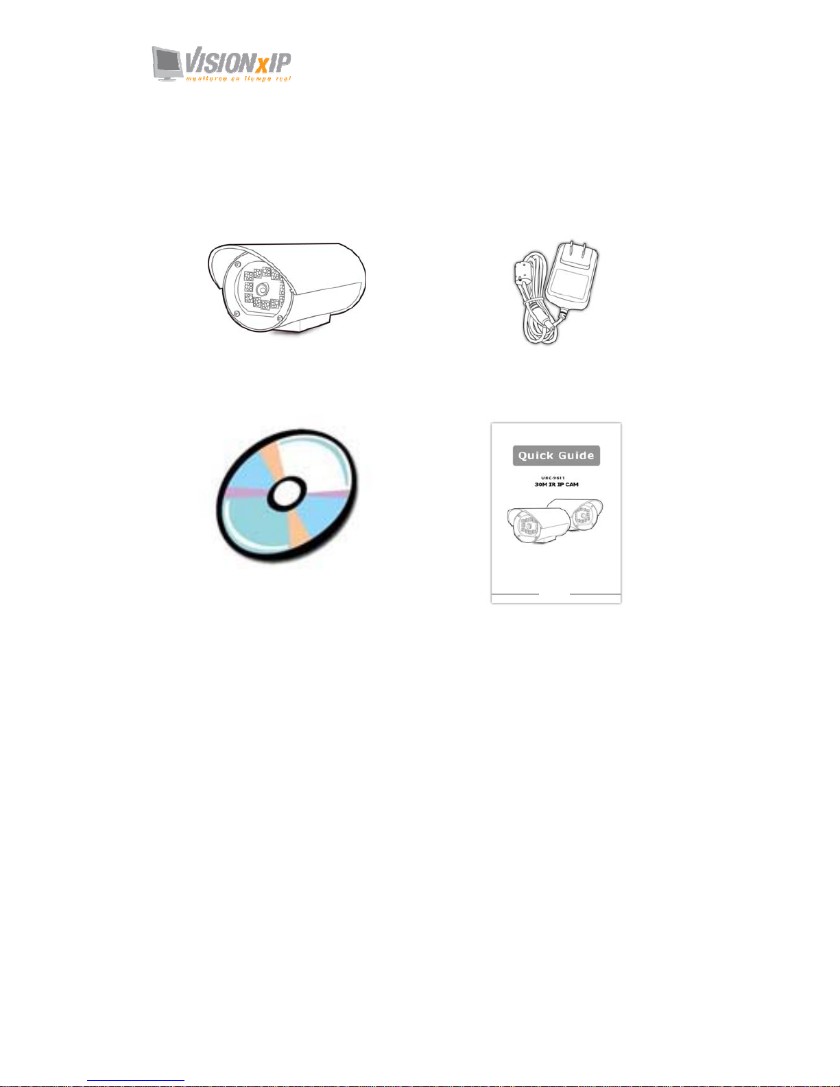
The 30 M / 25M IR Network Camera is provided with the following accessories.
Please contact your dealer if any one of the following is missing.
1. 30 M / 25M IR Network Camera 2. 12V DC Power Supply
(Only available for 25M IR model)
3. CDROM
(Including User Manual / ip finder / NVR setup /
NVR manual/ Quick Guide)
4. Quick Guide
Page 4
Mail: [email protected]
Web: www.visionxip.com
4
System Requirements
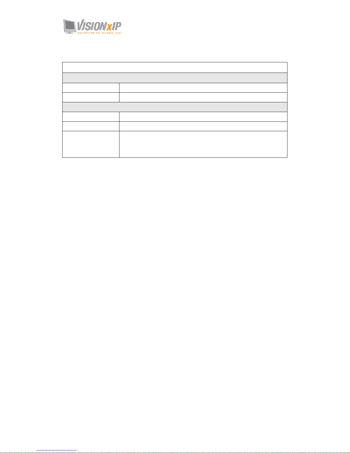
30 M / 25M IR Network Camera
Internet Environment
LAN 10/100M Ethernet
Wireless LAN 802.11b or 802.11g
Monitor System Requirements
OS support Windows 2000 Professional SP4, XP Home SP2
Browser support Internet Explorer 6.x or later
Hardware CPU: Pentium 4 2.4 GHz or later
Memory: 256 MB (512 MB recommended)
VGA card resolution: 800 x 600 or higher
Page 5

Mail: [email protected]
Web: www.visionxip.com
5
Introduction
The 30 M / 25M IR Network Camera is a multi-functional stand-alone IR CCD
Network Camera that can connect to Ethernet, LAN, or any broad-band networks.
Equipped with 12/8 High-light & long life LED, the camera can provide up to 20,000
hours IR function. The 30 M / 25M IR Network Camera carries a rating of IP 66,
keeping the electronic equipment dust-tight and dry in the strongest storms to provide
maximum security against equipment damage. The camera uses SONY CCD sensor
provides vivid image for your best surveillance purpose. Unlike traditional CCTV
cameras, the 30 M / 25M IR Network Camera has a built-in CPU and webpage server
to provide users with a mechanism for home security or remote office monitoring
applications. The 30 M / 25M IR Network Camera supports 3GPP real-time video
streams that allow you to control the home or office environment using a 3G mobile
phone. The 30 M / 25M IR Network Camera is easy to install and use. The built-in
webpage server enables you to control the security and property of your home or
offices remotely and easily from anywhere there is a networked computer.
Features and Advantages
The 30 M / 25M IR Network Camera is a stand-alone IR CCD Network Camera. It
can operate smoothly without the need to install additional software or hardware. All
that is needed is a PC equipped with IE browser (6.0 or above) connected to the
Internet Camera via the network to monitor pre-set places remotely. The 30 M / 25M
IR Network Camera provides great remote accessibility of personal, home, and assets
just as though you were really there.
The 30 M / 25M IR Network Camera features:
z 1/3"Sony CCD color image sensor to ensure clear and vivid imaging effect;
z MPEG4/MJPEG dual video compression mode and dual coding mechanism for
multiple applications;
z 12/8 pcs High-light & long life LED, the camera can provide up to 20,000 hours
IR function.
z Use international IP66 housing standard for providing maximum security against
equipment damage.
z Support of 3GPP real-time video streams that allow you to control home or
office environments using a 3G mobile phone;
z Built-in smart motion detection to monitor abnormal situations automatically and
transmit real-time according to pre-set trigger commands;
z Built-in webpage server that allows easy control via the Internet;
z Dynamic IP domain name support for use of the product at locations where a
fixed IP is not available;
z Access setting by level to ensure security and protection of life and property;
z Elegant style suitable for homes, studios, offices, clinics, and retail shops;
Page 6
Mail: [email protected]
Web: www.visionxip.com
6
System Introduction
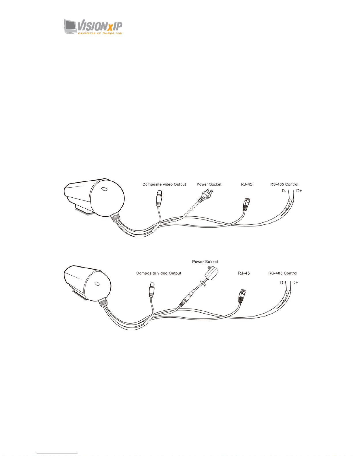
1. AC power cable: The AC input connector has a socket to connect the product to a
power source.
2. Ethernet connector: An RJ-45 connector is provided for connection to the
10Base-T Ethernet cable or 100 Base-T High Speed Ethernet cable. This port can
automatically detect or coordinate the transmission rate of the network.
3. Use a video/audio output cable for external video/audio transmission if required.
The video source use BNC connector, you can purchase the connector from your
nearby electric material shop.
4. RS-485 port: If an additional rotary stage is required, please use this product at
the rotary stage from the RS-485 port. This product supports rotary stages using
Pelco P and Pelco D protocols.
30 M IR Network Camera Connecting Diagram
25M IR Network Camera Connecting Diagram
Page 7
Mail: [email protected]
Web: www.visionxip.com
7
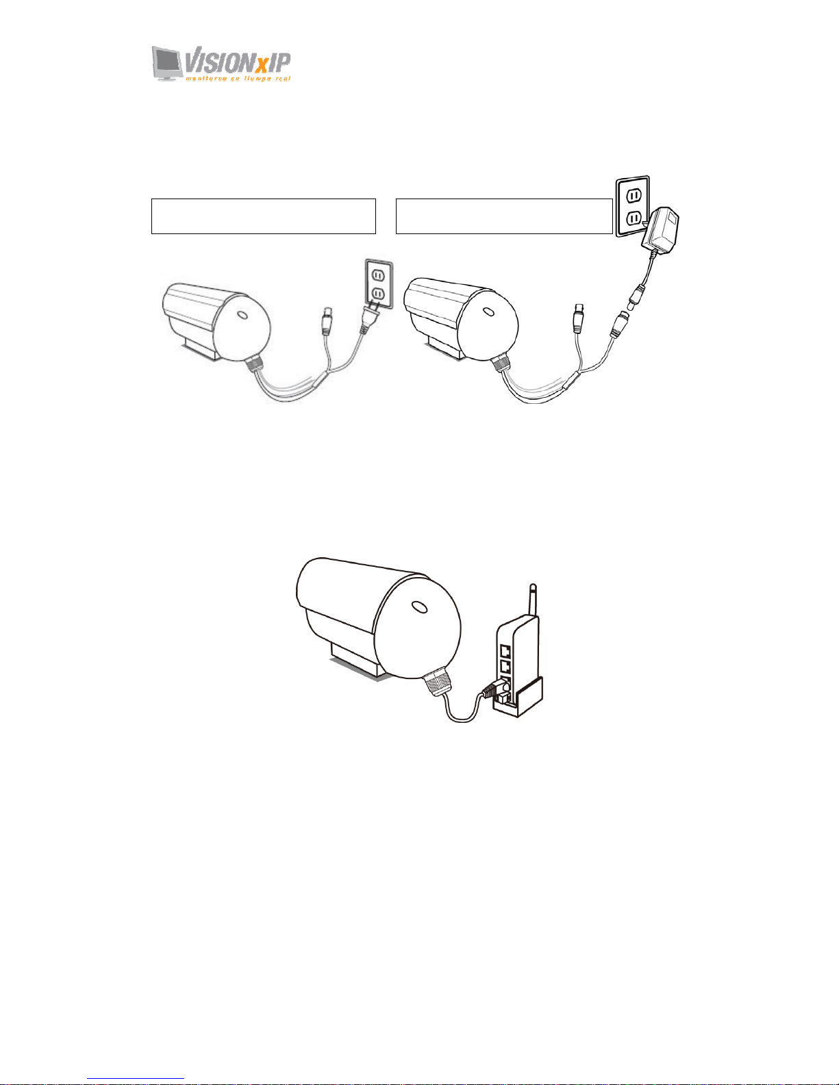
AC Power
Plug the power cable in the power socket on the product.
Video Output
Plug the video output cable into the monitor or recording equipment.
LAN Socket
Connect the LAN cable into the LAN socket.
RS-485 port
If you have a rotary stage using a RS-485 interface, please connect it to the product
with an RS-485 cable. For detailed information, please refer to PTZ chapter for more
description.
30 M IR CAM Power Connection 25 M IR CAM Power Connection
Page 8
Mail: [email protected]
Web: www.visionxip.com
8
Hardware Installation
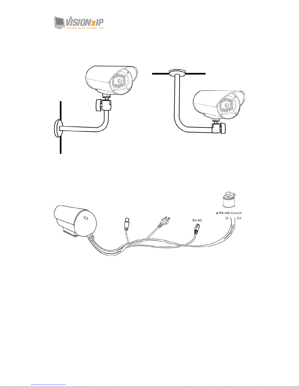
a. Product location: You can install the product on the holder and hang it on the wall
or ceiling. Please do not install this product in locations of poor ventilation. This
will result in poor operation.
b. If you have an RS-485 rotary stage, please connect this product to the stage from
the RS-485 port. Please make sure the poles must be correctly connected.
c.
1. Connecting to LAN
Please connect the camera to your network with a LAN cable from the LAN
Socket.
2. Connect to the power source
Plug one end of the attached power cable in the power socket of the product and
connect the other end to the AC power source.
Note: After connecting the product a power supply, you can check if it is on from the Status LED
on the front.
Page 9
Mail: [email protected]
Web: www.visionxip.com
9
Camera Settings
After the hardware has been installed, insert the supplied CD in the computer and
execute the file IP FINDER.EX following the steps below to search for and change
the IP address of the camera.
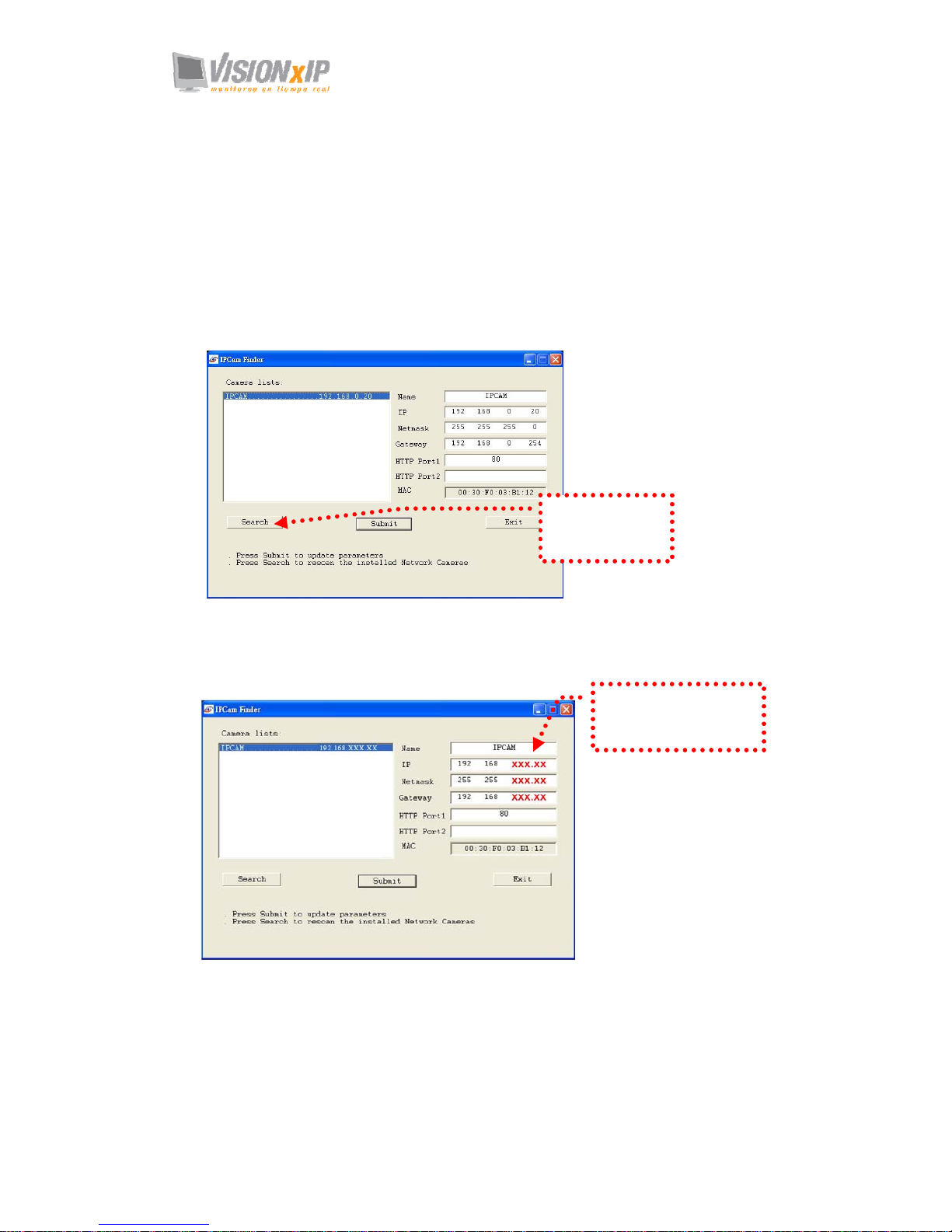
1. Start the machine.
Execute the IP Finder.exe from the supplied CD.
2. Find the camera (Search)
Search for the product from your LAN. The factory IP setting 192.168.0.20
appears on the screen.
3. Changing the IP address and related settings for the network environment
When you find the camera, click it and the settings will appear on the right side.
Change the settings for the new network environment you need.
※ You must enter new settings in the IP, Netmask and Gateway fields and keep
the settings in other fields unchanged.
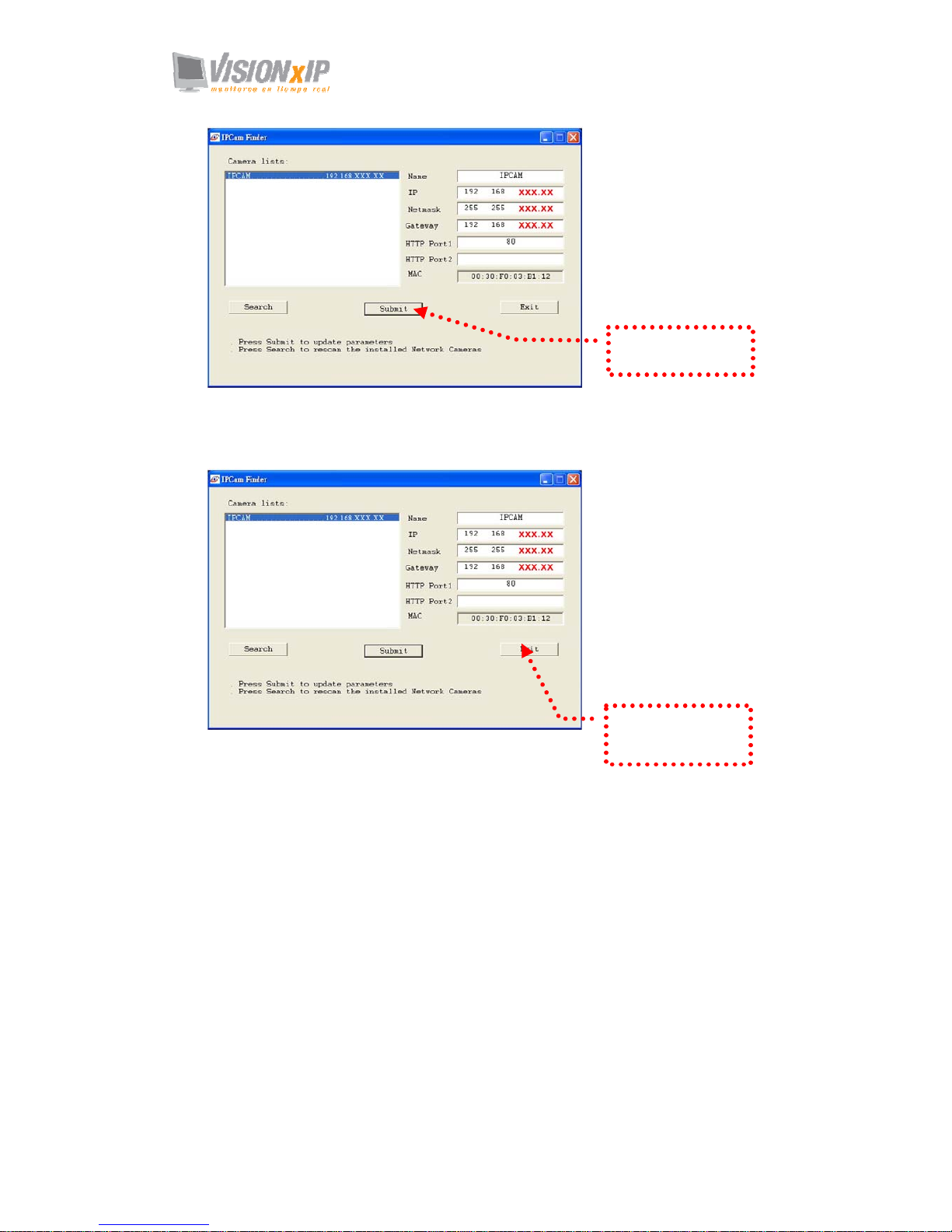
4. Submit data (Submit)
Click Submit to validate new settings.
1. Click Search to
find the IPCAM on
the LAN.
2. Enter the settings for the
new network environment
you need.
Page 10
Mail: [email protected]
Web: www.visionxip.com
10
5. Confirmation
When all changes have been confirmed, click “Exit” to quit.
Notes:
1. The I P FINDER can only find the I P addresses of cameras that share the same hub on the LAN.
For information about finding IP addresses on the Internet, refer to the “DDNS Setting”, or “UpnP
Setting”.
2. All of our camera/network server products can be found and changed using the IP FINDER
software.
3. If the IP FINDER software cannot be executed, check your antivirus software or firewall to
remove the block.
4. Field description: You can give a name to your camera (such as “PT_IP” or “PT-IP”). No spaces
allowed (such as “PI IP”).
You can change the settings for IP, Gateway Address and Network Mask to meet the requirements
of your network environment. The product uses HTTP Port1 and does not support Port2 setting s .
MAC: Factory default network identity of the machine.
3. Click Submit to
validate new settings.
4. When all changes
have been confirmed,
click Exit to
q
uit.
Page 11
Mail: [email protected]
Web: www.visionxip.com
11
Camera Setting from a Router
You can use DHCP when you want to use the camera on the Intranet (LAN). However,
the IP must fixed when you want to use the camera on a WAN. For this application, it
is required to set up a virtual server on the ADSL router. Follow the steps below to
complete the setting:
1. Enter the camera setting page to set a fixed IP. (Refer to the “Network Setting”.)
Ex.: 192.168.0.49
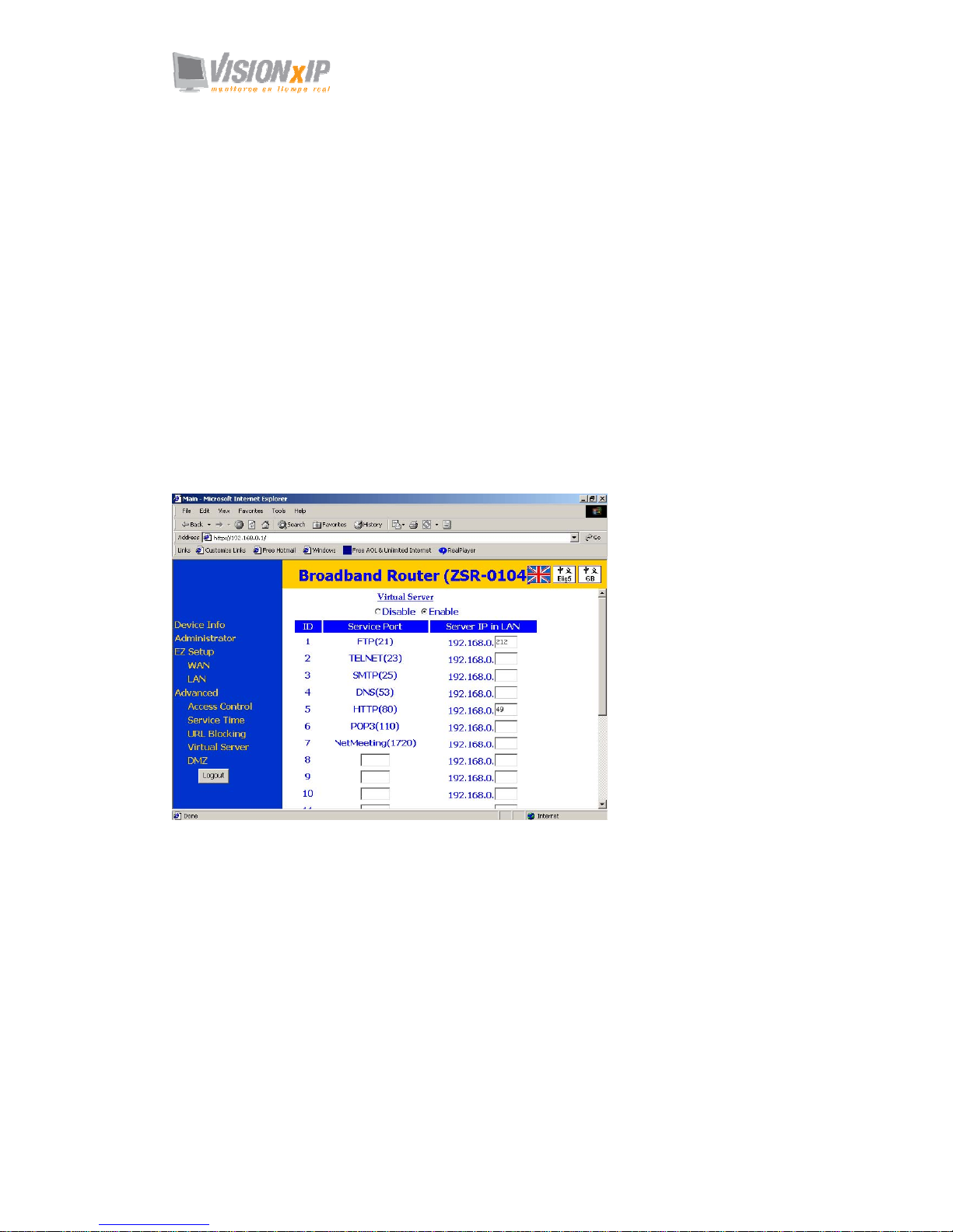
2. Enter the ADSL router main setting page. Ex.: Zonet ADSL router
3. Enter the Virtual Server setting page.
a. Set “mapping of HTTP Port (80) to 192.168.0.49 ”.
b. Restart ADSL router.
After completing the settings, you can operate the camera from a WAN IP Address
via the ADSL router.
Example: The Virtual Server setting screen of the Zonet ADSL router
Note: The virtual server of setting screen is not the same for all ADSL routers. Refer to the manual of
the ADSL router you purchased for more information about the setting.
Page 12
Mail: [email protected]
Web: www.visionxip.com
12
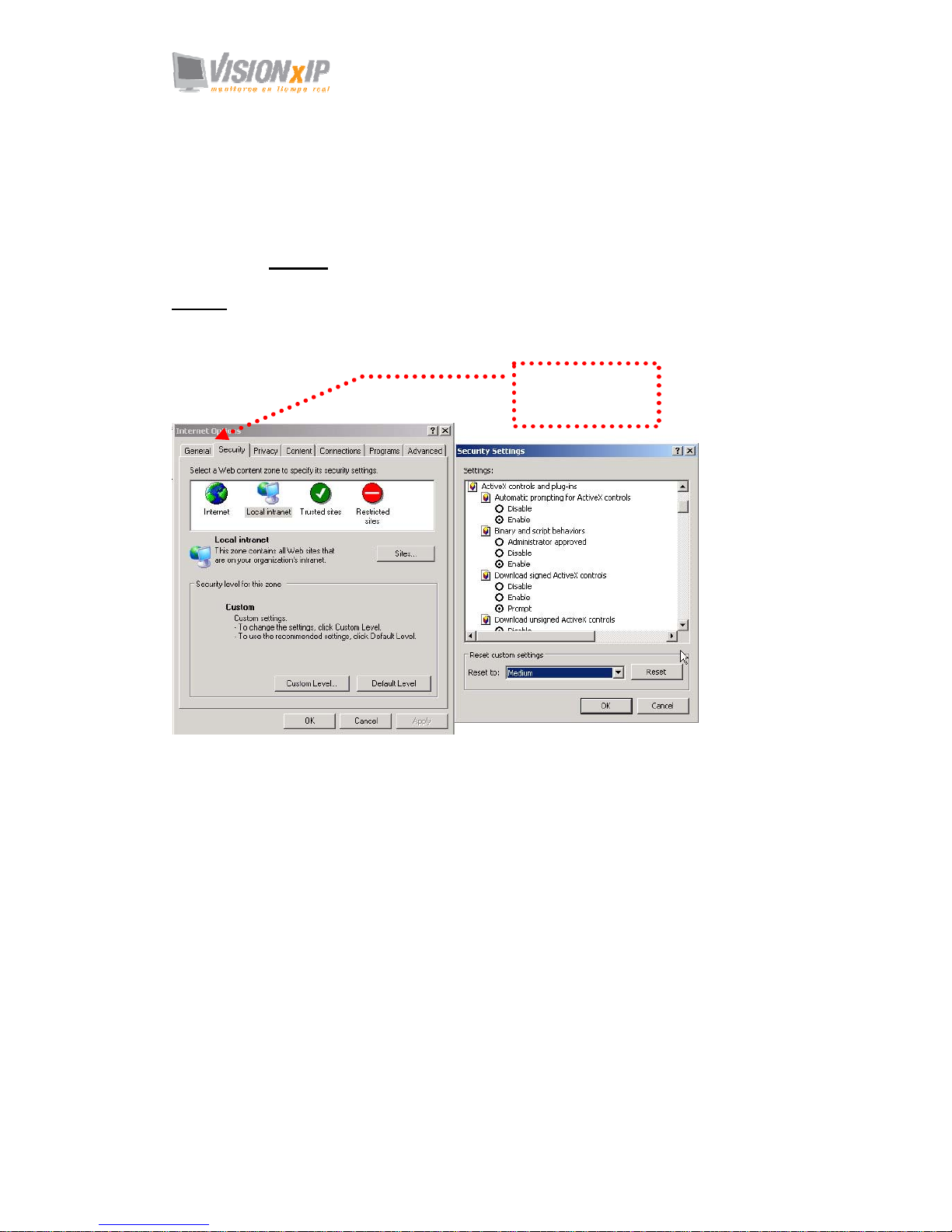
Change the Internet Explorer Setting
This product uses ActiveX Control to play images and sound on your PC. The
ActiveX Control application software will be downloaded to your PC when you
connect it to the Internet. To ensure successful download of the software, the Internet
Explorer "security settings" must be changed accordingly. Make sure that the security
level is set to Level II, the commonly used default security level.
Steps:
Open the IE browser Î Tools Î Internet Options Î Security Î Custom Level
Check the security setting
Note: This product supports IE 6.0 or above.
Check that the
security level is
Level II.
Page 13
Mail: [email protected]
Web: www.visionxip.com
13
Enter the Main Page
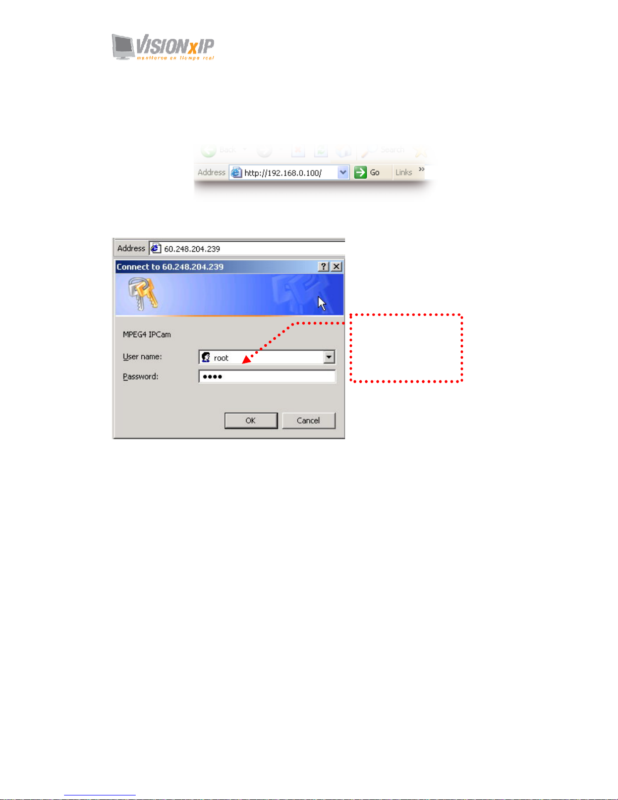
1. Open the IE browser and key in the IP address of the product.
Key in the IP address of the camera
Camera login screen
2. Key in the default “username” and “password”.
Default User Name: root
Default Password: root
You can access the camera as an administrator by default and set up for other
users or privileges from the “Basic Settings” -> “User”.
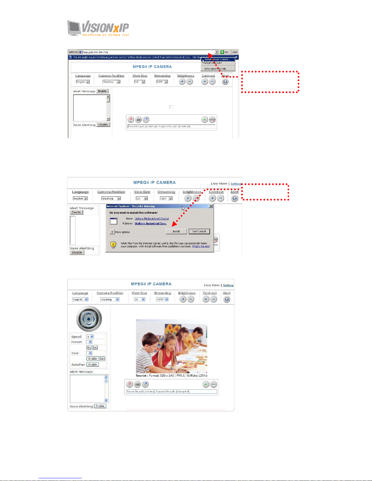
3. Installation of Internet Explorer ad-hoc components
When the username and password are confirmed, a control setup screen pops up
under the IE address bar. Click “Install ActiveX Control” to install the controls.
When the login screen
appears, key in "root" in
the User Name and
Password fields. Click
OK.
Page 14
Mail: [email protected]
Web: www.visionxip.com
14
Setup prompt screen
4. The security warning screen appears. Click "Install".
The ActiveX Control is named "UIC ActiveX Control". This software is owned by
UIC and well certified. You can use it without any doubts about its validity.
5. When ActiveX Control is installed successfully, you will see the camera image
and interface.
Camera main page and image
Click “Install
ActiveX Control”.
Click “Install”.
Page 15
Mail: [email protected]
Web: www.visionxip.com
15
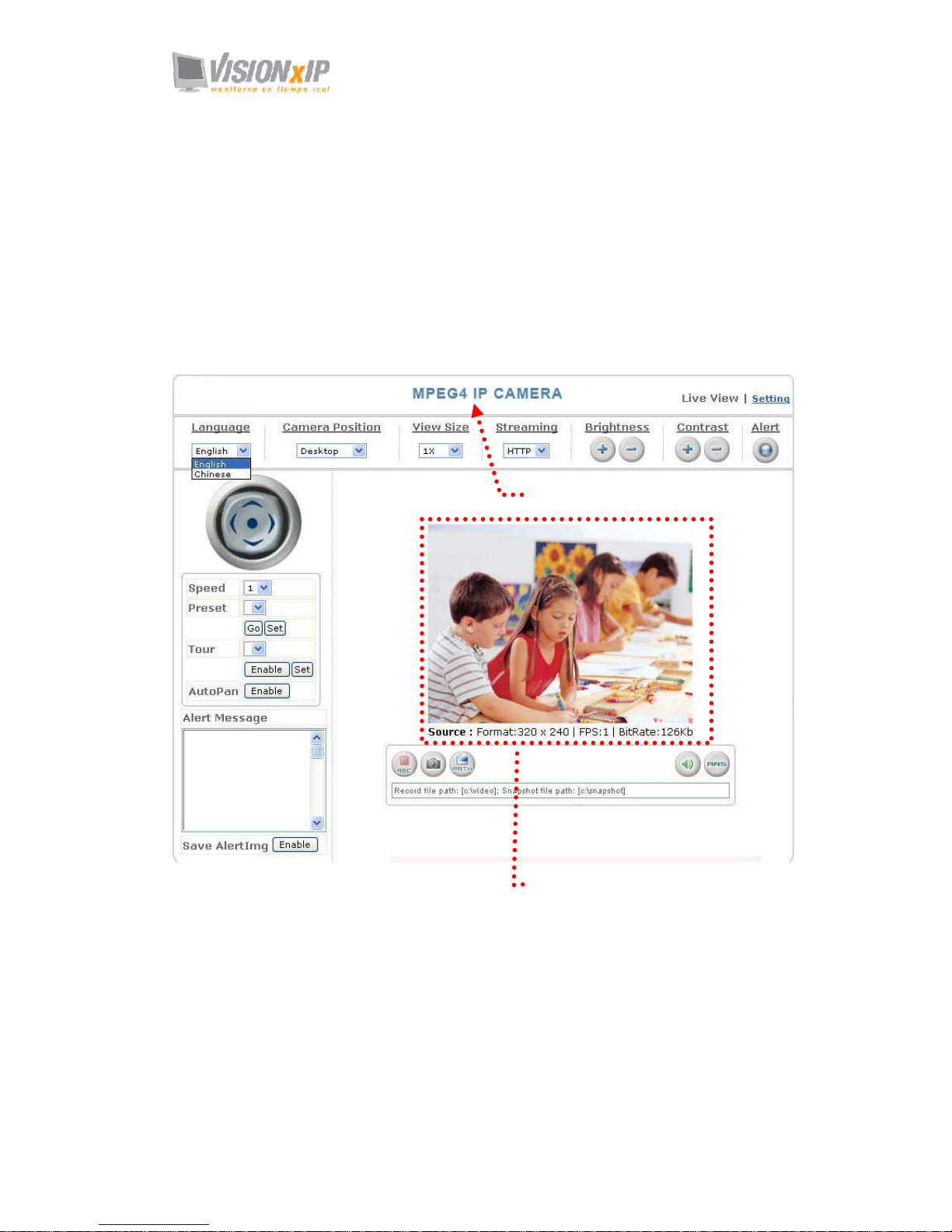
Camera Main Page
Descriptions:
Source: Information bar
1. Format: resolution of the current video stream
2. FPS: Frame Per Second of the current video stream
3. BitRate: bandwidth per second of the current video stream
Attention: Please change the streaming setting to HTTP if nothing appears in the image area.
Image area
Product name
Page 16
Mail: [email protected]
Web: www.visionxip.com
16
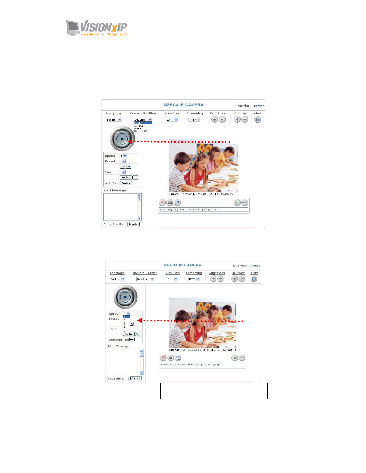
Control panel
Note: Camera functions can only be used on a rotary stage. See the Rotary Stage section for
details.
1. Camera direction: controls the direction of the camera (up, down, left, right,
home position).
2. Camera speed: controls the rotation speed of the camera from “1” (lowest) to
“7” (highest). This function must work with the characteristics of the rotary
stage.
Speed 1 2 3 4 5 6 7
Angle/Sec. 3 20 40 60 80 100 120
Direction control.
Rotation speed.
Page 17
Mail: [email protected]
Web: www.visionxip.com
17
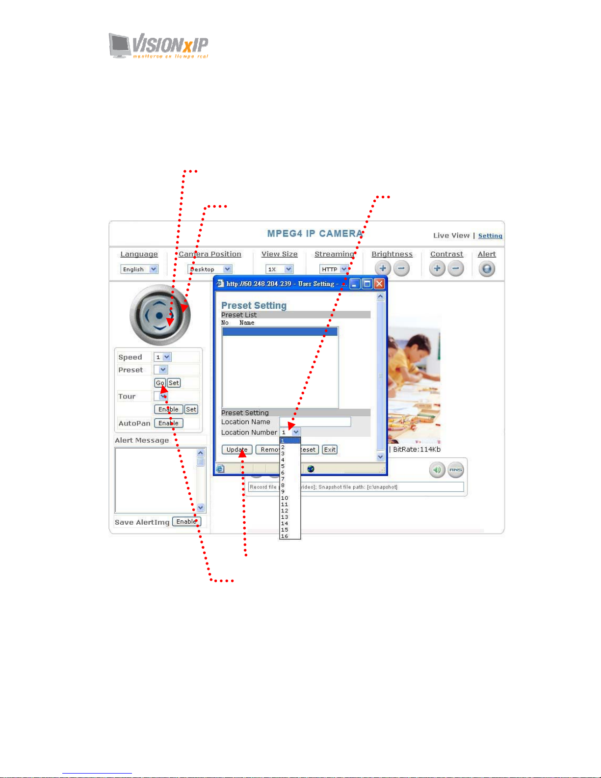
3. Preset: presets the rotation points for the camera (16 points)
This function allows you to preset the points you wish to monitor. Then you can
assign a code to each point. The rotary stage will automatically rotate to this preset
point once you press the assigned code. It can save time and labor of manual
control. More importantly, it is more accurate. This function must work with a
rotary stage.
4. Click Update to exit.
1. Click Set to enter the Preset Setting screen.
2. Enter the name of the
location.
3. Control the camera direction.
5. Select the number you need and click Go. The
camera moves to the area automatically as set up
by the selected number.
Page 18
Mail: [email protected]
Web: www.visionxip.com
18
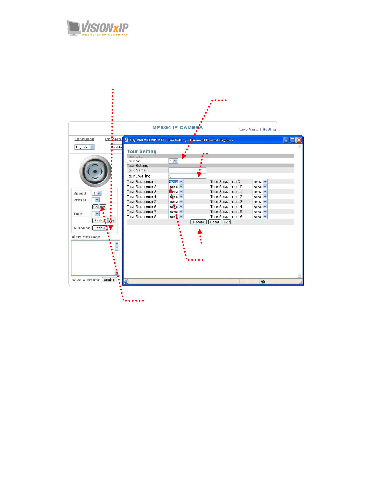
4. Tour: enables/disables the tour mode of the camera.
The rotation points of the camera must be set up in advance.
This function allows you to set up to 5 cruising routes.
This function must work with a rotary stage.
1. Click Set to enter the Tour Setting screen.
2. Name the tour. You can set
up 5 tour groups at
maximum.
3. Dwelling time (sec.) at each tour point.
4. Select a preset location for the
camera.
5. Click Update to Exit.
6. Click Enable to activate the tour function.
Page 19

Mail: [email protected]
Web: www.visionxip.com
19
5. AutoPan: enables/disables AutoPan.
You can enable the AutoPan function to make the camera automatically move
back and forth horizontally. Disable the AutoPan function to stop the scan. This
function must work with a rotary stage.
6. Alert: displays alert trigger
This indicator flashes to warn you when a movement or alert is detected. Click to
stop the flash.
7. Alert Message: enables/disables the alert message display.
Alert Message: displays the alert message. Press Enable/Disable to enable or
disable the alert display message. When this function is disabled,
the alert message will not be displayed.
Save AlertImg: saves the alert message. Press Enable/disable to enable or disable
the save of the alert image in the Snapshot directory. When the
Save AlertImg function is enabled, double-click it to show the
alert image. A message appears whenever an alert is triggered (50
messages at maximum). The message disappears when you quit
the screen. (For more information about this setting, refer to the
Setting/Application Setting/Event/Event.)
AutoPan function
Enable/ disable the alert message
Save function
Alert trigger display
Alert message display area
Enable/ disable the alert message
displa
y
Page 20
Mail: [email protected]
Web: www.visionxip.com
20
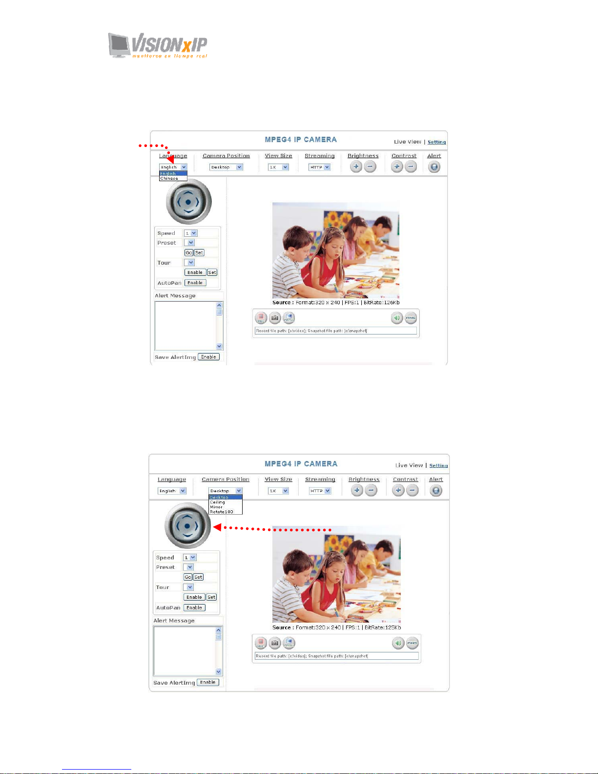
8. Language: selects a UI language
Tour languages are available: English, Simplified Chinese, Traditional Chinese
and Japanese.
9. Camera Position: sets the position for display of the image
Desktop: Normal image (displays on the desktop; default value)
Ceiling: Upside-down image
Mirror: Mirror image
Rotate 180: Mirrored and upside-down.
Selects a
language
Set the position for display of
ima
g
e.
Page 21
Mail: [email protected]
Web: www.visionxip.com
21
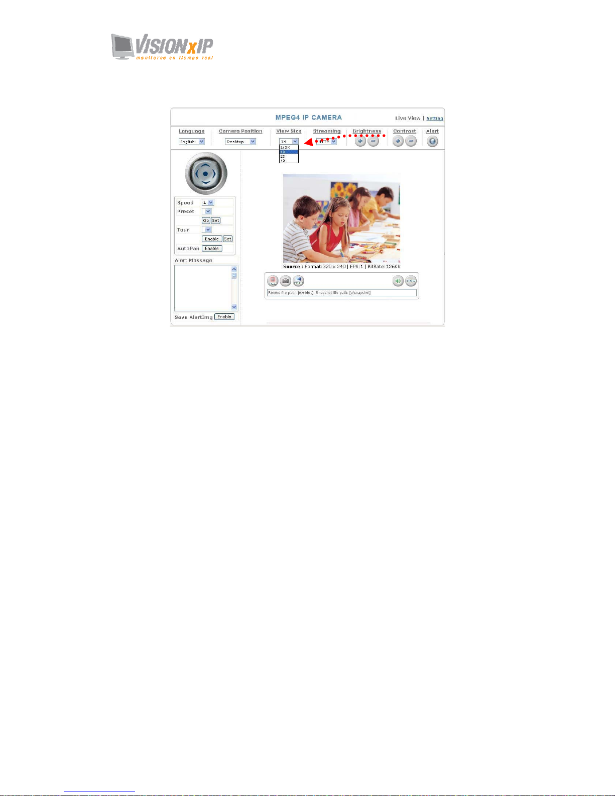
10. View Size: selects the size of the image
Select the size of the image from 0.5 to 4 X.
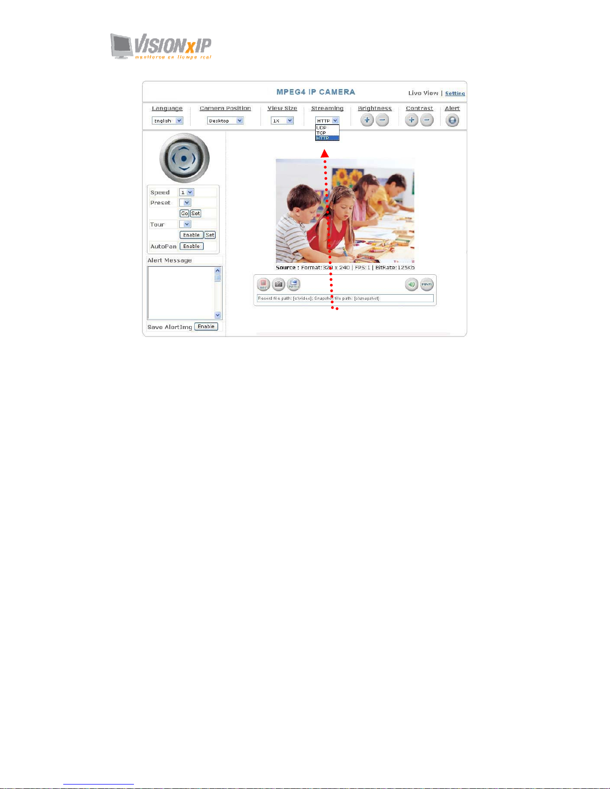
11. Streaming: sets the video stream protocol (HTTP is recommended)
This product provides three different video streaming protocols: UDP, TCP, and
HTTP. HTTP is recommended because it allows the video stream to go through
the firewall. (Refer to Setting/Basic Setting/Network/Streaming for more
information).
UDP: provides the fastest but most unreliable transmission service. Video steams
are transmitted through UDP Port (50000~60000 by default) to ensure the
fastest image transmission. However, video fragment or mosaics may occur
due to poor transmission quality.
TCP: provides reliable data transmission. Video steams are transmitted through
RTSP Port (554 by default) to avoid video fragment or mosaics due to poor
transmission quality.
HTTP: Video streams are transmitted through HTTP Port (80 by default) to ensure
passing through firewalls.
Select an image size
Page 22
Page 23
Mail: [email protected]
Web: www.visionxip.com
23
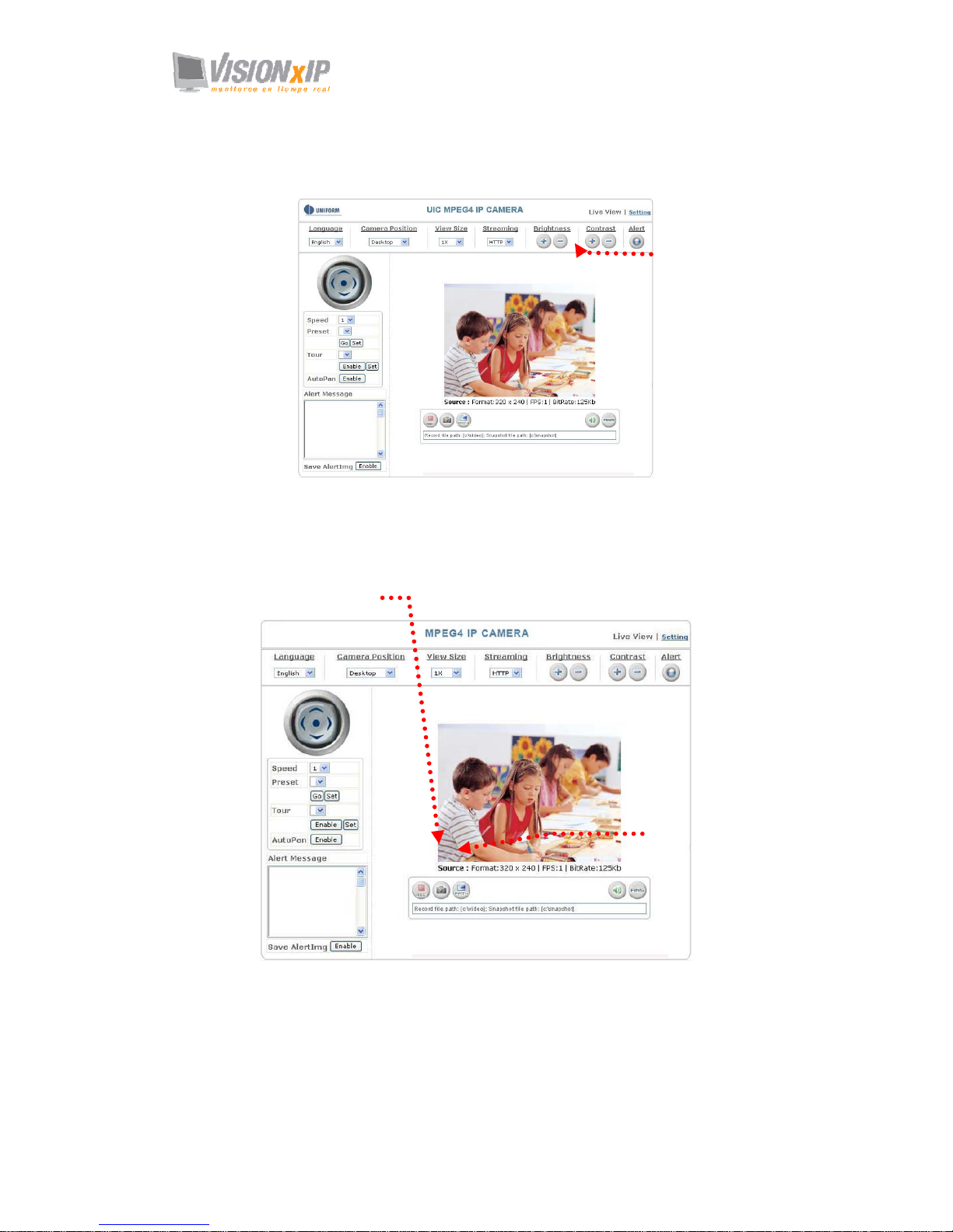
12. Brightness: adjusts video brightness / Contrast: adjusts video contrast
Press + (increase) or ﹣ (decrease) from the setting window to adjust the brightness
or contrast of the image.
13. REC: executes the video recording function
Click this button to start video recording and save the image file in the preset
directory (C:\video). A red mark appears at the bottom left corner of the image
when the recording function is running.
14. Snapshot: executes the snapshot function
Click this button to capture an image and save it to the preset directory.
(C:\snapshot).
Adjust brightness/contrast
of the image
Recording button
Snapshot button
Page 24
Mail: [email protected]
Web: www.visionxip.com
24
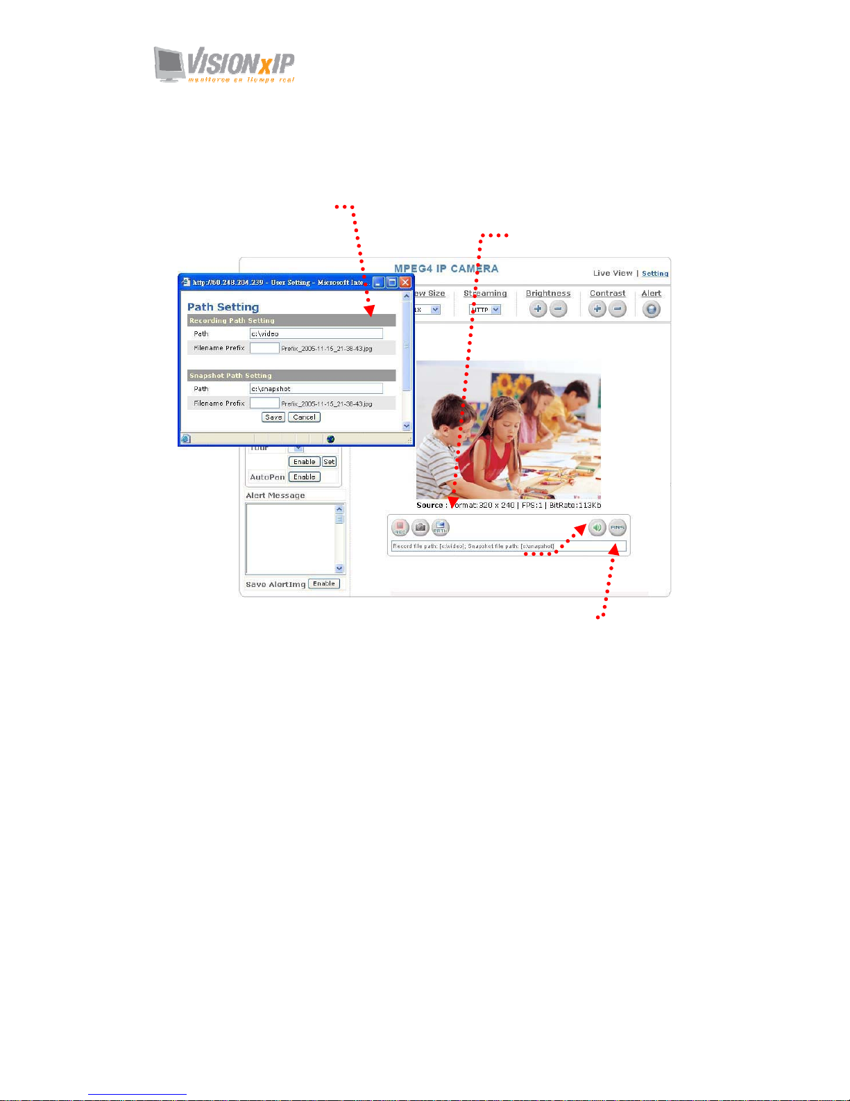
15. Path: sets the save path and name for recorded images and snapshots.
The filename is the recording date by default. You can identify the file by prefix
of the filename.
16. Audio On/Off: turns on/off the pickup function
Click the button to mute the sound from the built-in microphone. A cross-out
mark appears on the speaker icon to indicate the mute status.
17. ANS: Automatic Noise Suppression system. (The ANS function is enabled by
default and it is recommended to keep this function enabled.)
This function can suppress background noise around the camera (such as regular
fan noise). Click the button to disable the ANS function. A cross-out mark appears
on the ANS icon to indicate the noise suppression status.
Save the path
Click the Path field to
select the folder to save
the file.
Pickup
function
Automatic Noise Suppression system
Page 25
Mail: [email protected]
Web: www.visionxip.com
25
System Settings
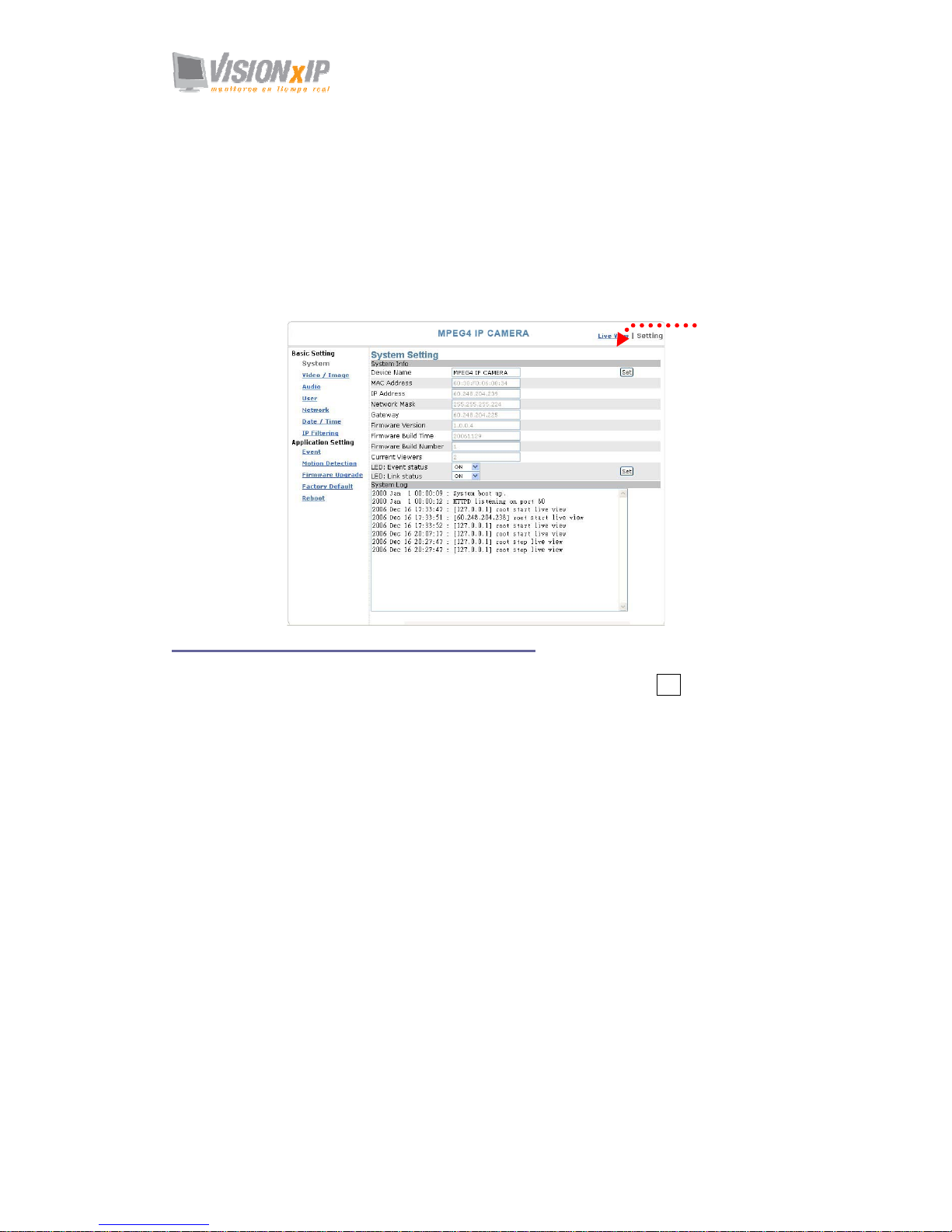
System setting contains basic and application settings. The basic setting is executed
for basic system information, transmission speed, audio/video code, user authorization,
date/time, and IP filter, while the application setting is executed for event triggering
definition and other relevant settings, definition of the motion detection area,
firmware update, reset to factory default, and reboot.
Basic Settings
Basic Setting > System (System info)
Basic Setting > System > System Info
Device Name: You can set the name for your camera here. Click Set to complete
the setting.
MAC Address, IP Address, Network Mask, and Gateway: Network information.
Firmware: Firmware version information.
Current Viewers: The number of viewers who are currently accessing the video
stream.
LED: Event status: You can set the LED display mode (ON, OFF, Flash) here.
ON: The LED fla s hes when any motion detection or alert trigger is
identified.
OFF: LED is turned off.
Flash: LED flashes according to the user-defined interval.
LED: Link status: You can set the LED display mode (ON, OFF, Flash) here
ON: The LED lights up green when a video stream is detected.
Otherwise, it does not activated.
OFF: LED is turned off.
Flash: LED flashes according t o the user-defined interval.
Basic Setting > System > System Log
The administrator can view all login information of this camera, including boot
record, video streaming mode, login IP, changes, and the date/time information.
You can copy the entries to a Word document and save them manually. Please
Click Setting to enter
the setting page
Page 26

Mail: [email protected]
Web: www.visionxip.com
26
note that all information is deleted when you turn off the machine.
Page 27
Mail: [email protected]
Web: www.visionxip.com
27
Basic Setting >Video/Image
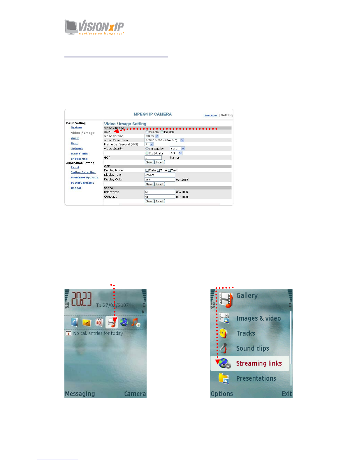
Basic Setting > Video Image > Video Image
Basic Setting > Video / Image > Video Image > 3GPP
To view the camera image using a 3G cellular phone, click Enable to enable the
3GPP mode. (Note: When the 3GPP mode has been activated, all relevant
parameters are set automatically and cannot be changed. This is for the sake of
compatibility).
To use the 3GPP function, the following requirements must be met. Contact your
telecom company to learn more about the connection conditions):
1. 3G phone: Your cellular phone functions properly and supports 3G service.
The compatible cellular phones that have passed our test are: Nokia 6630,
Nokia N73, Wibo WinII, Nokia E61, Nokia N70, Nokia N93
2. 3G phone number is available.
3. The 3G wireless networking service is available.
4. The camera has a fixed IP address.
5. The 3GPP mode is activated.
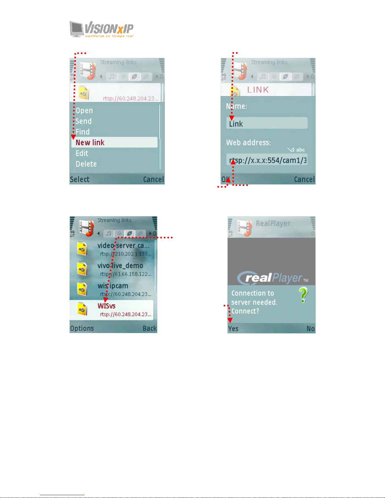
Ex: Nokia N71. Follow these steps to set up your 3G viewing function.
3GPP mode
1.Enter multimedia data from
the main screen.
2. Select a streaming link
Page 28
Mail: [email protected]
Web: www.visionxip.com
28
3. Add a new link.
4. Enter the link name.
5. Enter the IP address of the camera, e.g.
rtsp://xxx.xxx.xxx.xxx:554/cam1/3gpp
7. Select this
stream name to
proceed with
linking.
8. Select
“Yes” to
connect.
6. Select OK to save
the setting.
Page 29
Mail: [email protected]
Web: www.visionxip.com
29
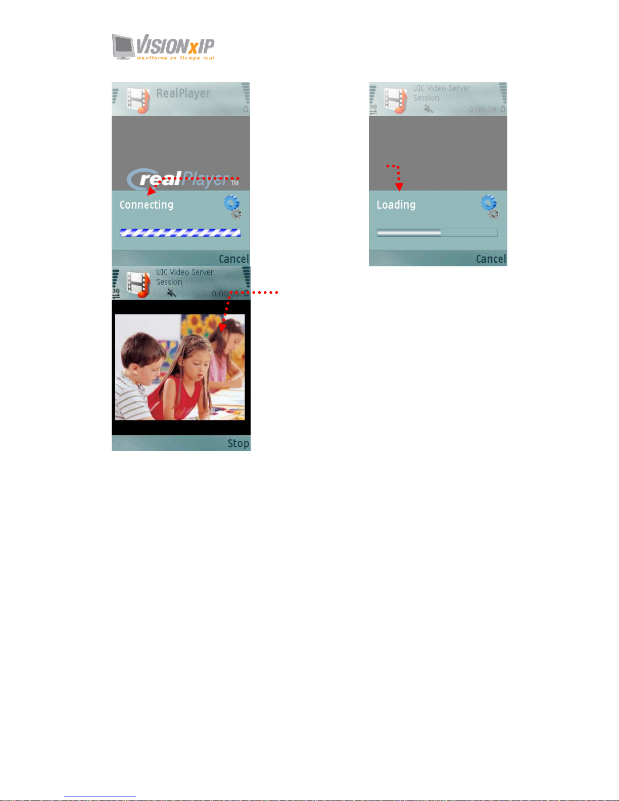
9.
Connecting.
10. Loading
the image.
11. Video stream
screen .
Page 30
Mail: [email protected]
Web: www.visionxip.com
30
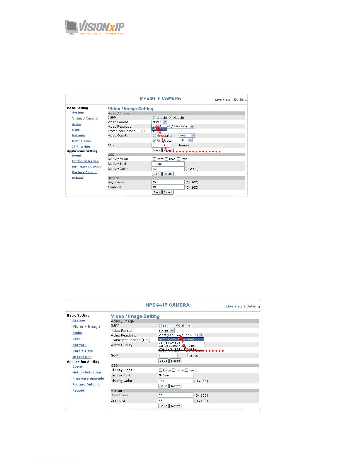
Basic Setting > Video / Image > Video Image >Video Format
You can select MPEG4 or MJPEG as the video format. It is recommended to
select MPEG4 for real-time browsing to optimize the bandwidth. MJPEG is a
good choice for the best resolution when video recording is required for
collection of evidence.
Basic Setting > Video / Image > Video Image >Video Resolution
Generally speaking, selection of resolution is dependent on the bandwidth of the
network you are using. This product offers different selections for video/audio
settings. However, to ensure undisrupted image transmission, you need a higher
uploading bandwidth. Generally, it is recommended to use CIF resolution for
normal bandwidth. To meet other requirements, refer to Attachment B for more
information.
The product offers 4 image resolutions (PAL/NTSC):
1. D1 (704x576 / 704x480)
2. VGA (640x480)
3. CIF (352x288 / 352x240)
4. QCIF (176x144 / 176x112)
Select a video streaming format
Select an image
resolution
Page 31
Mail: [email protected]
Web: www.visionxip.com
31
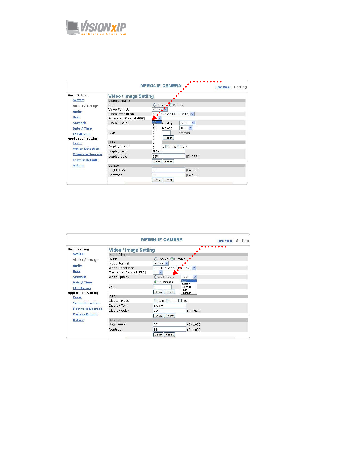
Basic Setting > Video / Image > Video Image >Frame per Second (FPS):
With NTSC, you can choose 1, 2, 3, 4, 5, 6, 7, 10, 15 or 30 for video resolution
With PAL, you can choose 1, 2, 3, 4, 5, 6, 12 or 25 for video resolution.
Basic Setting > Video / Image > Video Image >Video Quality
You can select Fix Quality (resolution priority) or Fix Bitrate (fluency priority) at
the same bandwidth.
Five options are available for your choice: Best, Better, Normal, Fast, and
Fastest.
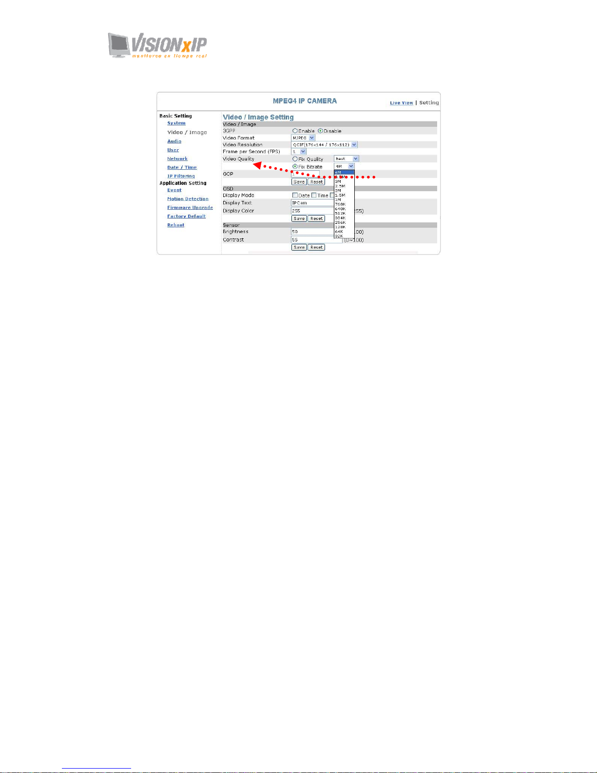
16 transmission speeds ranging from 32K to 4M are available in the Fix Bitrate
mode. The higher the transmission speed, the better the quality and fluency.
Select a FPS
Select a video quality
Page 32
Mail: [email protected]
Web: www.visionxip.com
32
GOP provides users with the function to set the pages of the I Frame and P
Frame to be transmitted in the MPEG4 mode. Basically, the I Frame page
contains the entire picture and needs higher bandwidth, while the P Frame page
only contains the parts that are different from the I Frame and need lower
bandwidth. Hence, when you need to transmit the pages without disruption in a
normal network environment, you can set up a higher GOP. For example, if GOP
25 is selected, 24 P Frame pages will follow 1 I Frame page, and so forth.
However, packets may be lost when they are transmitted in a congested network
environment. In this case, the following P Frame pages may bring about
disruption of the transmission because they lose the reference upon which the
difference from the I Frame is identified. You may change GOP to 10 with this
concern to avoid disruption of the transmission. The GOP is 15 by default.
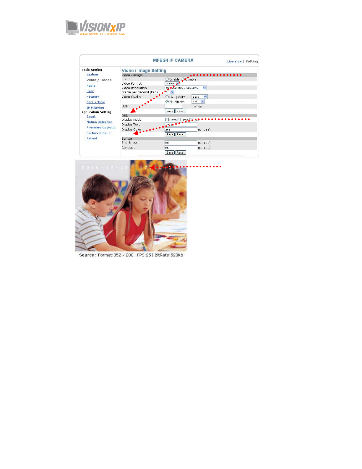
Basic Setting > Video Image > OSD
You can set to display the date, camera name and other information on the screen.
Basic Setting > Video Image > OSD > Display Mode
You can select to display the date (Date), time (Time) or text (Text).
Basic Setting > Video Image > OSD > Display Text
You can key in the text to be displayed on the screen (Ex.: Lobby IP Cam)
Basic Setting > Video Image > OSD > Display Color
256 colors and tones from 0 (deepest black) to 255 (lightest white) are available
for display of the text.
Basic Setting > Video Image > Sensor (brightness/contrast
adjustment)
You can adjust the brightness and contrast here.
Basic Setting > Video Image > Sensor > Brightness
You can adjust the brightness from 0 (darkest black) to 100 (brightest white).
Basic Setting > Video Image > Sensor > Contrast
You can adjust the contrast from 0 (max. contrast) to 100 (min. contrast)
Select GOP to update
the speed.
Page 33
Mail: [email protected]
Web: www.visionxip.com
33
Brightness/contract adjustment
OSD setting
Date, time, and text display
Page 34
Mail: [email protected]
Web: www.visionxip.com
34
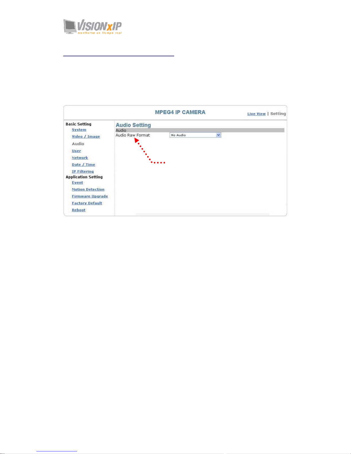
Basic Setting > Audio (Sound)
Basic Setting > Audio > Audio (sound setting)
Basic Setting > Audio > Audio > Audio Raw Format
You can select No Audio or PCM. When you select No Audio, the sound
transmission from the built-in microphone pauses. When you select PCM, the
sound transmission resumes. The factory default is PCM.
Sound transmission format
Page 35

Mail: [email protected]
Web: www.visionxip.com
35
Basic Setting > User(User)
The administration of the camera can set up access privileges by administrator,
operator, and viewer to ensure the security and control of the camera. The access
privileges and setting steps are described as below.
Basic Setting > User > User List (access privilege list)
The access privileges of the administrator, operator, and viewer are listed as follows.
The administrator has the right to define the privilege for each user depending on
requirements.
User Administrator Operator Viewer
Live View v v v
System Setting v v
Video Setting v v
3GPP v v
Audio Setting v v
Date / Time Setting v
User Setting root
Network Setting v
Wireless v
DDNS setting v
PPPoE setting v
Streaming v
UPnP v
SMTP v
SAMBA v
Notification v
IP Filter setting v
Event Setting v v
schedule setting v v
event server v v
trigger setting v v
Motion Setting v v
Firmware Upgrade root
Factory default v
Reboot Setting v
PTZ Control v User with PTZ
privilege
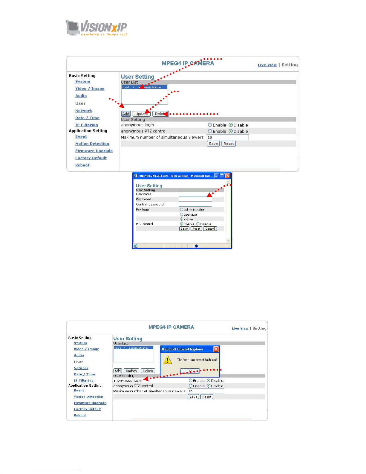
Steps: Click Add (to add a new user), Update (to change the privilege or password of
a user on the list), or Delete (to delete a user from the list) and complete required
fields. Then Click "Save" to complete the setting.
Options:
Add: Add a new user and set up a different privilege.
Update: Change the privilege or password of a user. You cannot change the
name of the user.
Delete: Delete a user from the list.
Page 36
Mail: [email protected]
Web: www.visionxip.com
36
Basic Setting > User > User Setting (privilege setting)
For special business situations, this product allows you to log in to browse without the
need of keying in your username and password. For this purpose, you need to check
“Enable” at Anonymous Login. To allow the user to control the camera, you need to
check “Enable” at Anonymous PTZ Control. However, “Disable” for both options is
recommended for the sake of security. Depending on the bandwidth and requirements,
a limit up to 10 viewer who are allowed to view the camera simultaneously can be
defined.
User setting
Add a new user and set up a
different privilege.
Change the privilege or password of a user. You
cannot chan
g
e the name of the user.
Delete a user from the list.
Log in the username, password and
privilege as required. You can also
define the PTZ control here.
Activate the anonymous view and
camera rotation functions; define the
number of viewers who are allowed for
on-line review simultaneously.
Page 37
Mail: [email protected]
Web: www.visionxip.com
37
Basic Setting > Network (Network Settings)
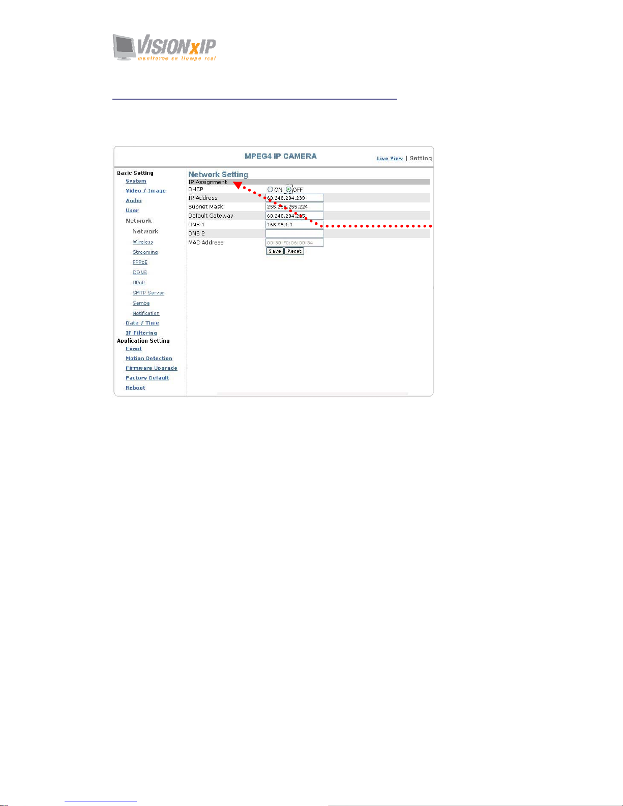
Basic Setting > Network > Network (cable network setting page)
Basic Setting > Network > Network > IP Assignment
DHCP setting:
DHCP(Dynamic Host Configuration Protocol) is a protocol that enables automatic
assignment of TCP/IP information to the client. Each DHCP client connects to the
DHCP server to access its network setting information, including IP address, gateway,
and DNS server.
The IP address of the camera is 192.168.0.20 by default when DHCP is "OFF". When
you select "DHCP ON" and access the DHCP network environment, the camera will
automatically send a DHCP packet to request an IP address. This IP address is
assigned automatically from the DHCP server on the network. No additional settings
are required for this page unless you need to change the network configuration. The
DHCP status of the camera is "OFF" by default.
Other settings:
For IP address, Subnet mask, Default gateway, DNS 1, and DNS 2, the DHCP server
will assign these values automatically when DHCP is in "ON" status; otherwise, you
need to key in the values manually.
Note: Where no IP address is assigned from the DHCP server, the system will set the Link-Local
Address automatically. Chunghwa Telecom DNS: 168.95.1.1
Cable network
setting page
Page 38

Mail: [email protected]
Web: www.visionxip.com
38
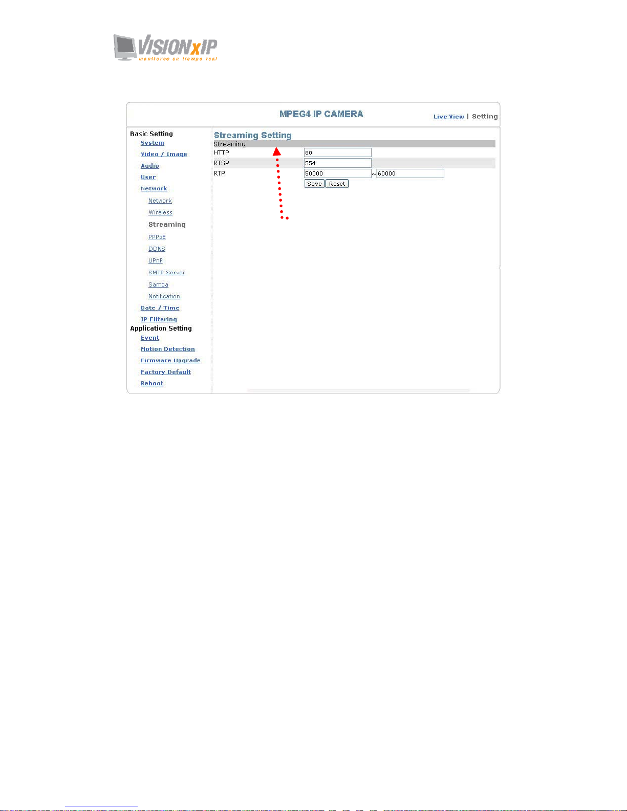
Basic Setting > Network > Streaming (steaming Setting)
Setting of the video steaming port (HTTP and factory default are recommended)
1. HTTP: Port 80 can pass through most firewalls. Video streams are transmitted
through HTTP Port (80 by default) to ensure passage through firewalls.
2. RTSP: Port 554 uses a fixed port (i.e. TCP) or can be defined by users to ensure
reliable data transmission. Video streams are transmitted through RTSP Port (554
by default) to avoid video fragment or mosaics due to poor transmission quality.
3. RTP: Port 50000 to 60000 are UDP ports and can be defined by users. They
provide the fastest but also most unreliable transmission service. Video streams
are transmitted through UDP Port (50000~60000 by default) to ensure the fastest
image transmission. However, video fragment or mosaics may occur due to poor
transmission quality.
Page 39
Mail: [email protected]
Web: www.visionxip.com
39
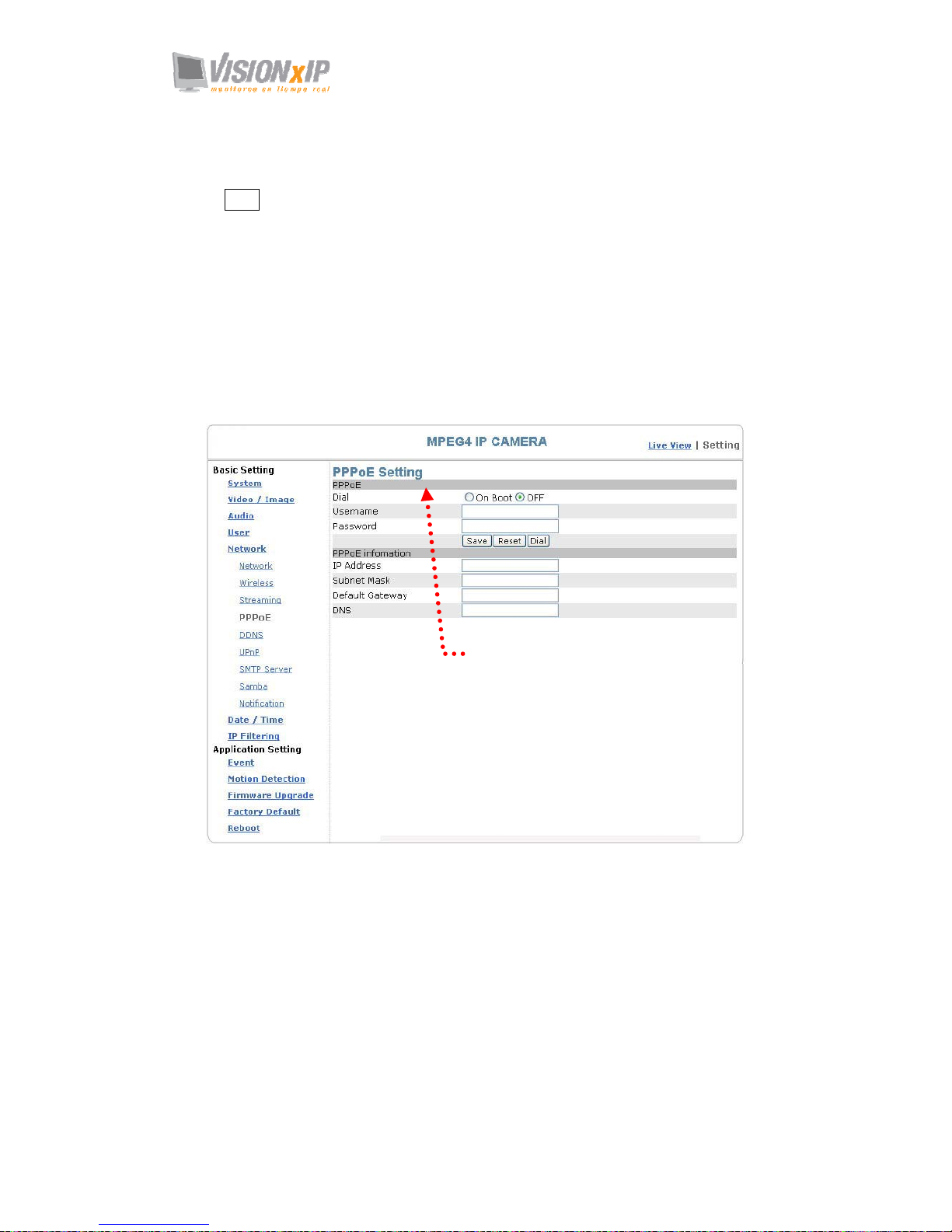
Basic Setting > Network > PPPoE (dial-up networking setting)
PPPoE: Point-to-Point Protocol over Ethernet is a protocol that supports access to a
high-speed wideband network using a PC and a wideband modem (such as xDSL,
Cable, Wireless modem). The user need only to equip the PC with an Ethernet card
and apply to an ISP (such as HiNet) and an ADSL provider (such as Chunghwa
Telecom) for ADSL service to roam the Internet through ordinary twisted copper
wires.
PPPoE: Point to Point Protocol over Ethernet is applicable to networking via a xDSL
or cable modem. PPPoE setting must be executed in the LAN environment for your
PC to connect to ADSL. Follow the steps below to complete the setting:
1. Dial: You can select whether or not to dial when you boot the machine.
2. Use DHCP or fixed IP for connection to the LAN environment.
Streaming port setting
Page 40
Mail: [email protected]
Web: www.visionxip.com
40
3. Key in the IP address of the camera and enter "PPPoE Setting" following the
route Setting Î Basic Setting Î NetworkÎ PPPoE.
4. Key in the xDSL "Username" and "Password" acquired from your ISP. Click
Save to confirm the setting.
5. Where the ADSL modem and the camera is connected via a switch-hub, you
can press “Reboot” or restart the machine manually to try PPPoE dialing when
the setting of the camera has been completed.
6. To observe the new IP address acquired when PPPoE dialing has been
executed successfully, follow the route Setting Î Basic Setting Î
NetworkÎNotification for the IP information. You can acquire the new IP
address via SMTP, FTP, and HTTP. Refer to the “Notification Setting” page
for more information.
Note: You can use the DDNS function to access the camera. Refer to the “DDNS Setting”
page for more information.
Basic Setting > Network > PPPoE > PPPoE
Dial: You can select whether or not to dial when you boot the machine (On Boot
or Off).
Username: Enter the username provided by your ISP.
Password: Enter the password.
Basic Setting > Network > PPPoE > PPPoE Information
IP Address: The IP address acquired when dialing has been executed
successfully.
Subnet Mask: The subnet mask information acquired when dialing has been
executed successfully.
Default Gateway: The gateway information acquired when dialing has been
executed successfully.
DNS: The ISP domain name acquired when dialing has been executed
PPPoE setting
Page 41

Page 42

Mail: [email protected]
Web: www.visionxip.com
42
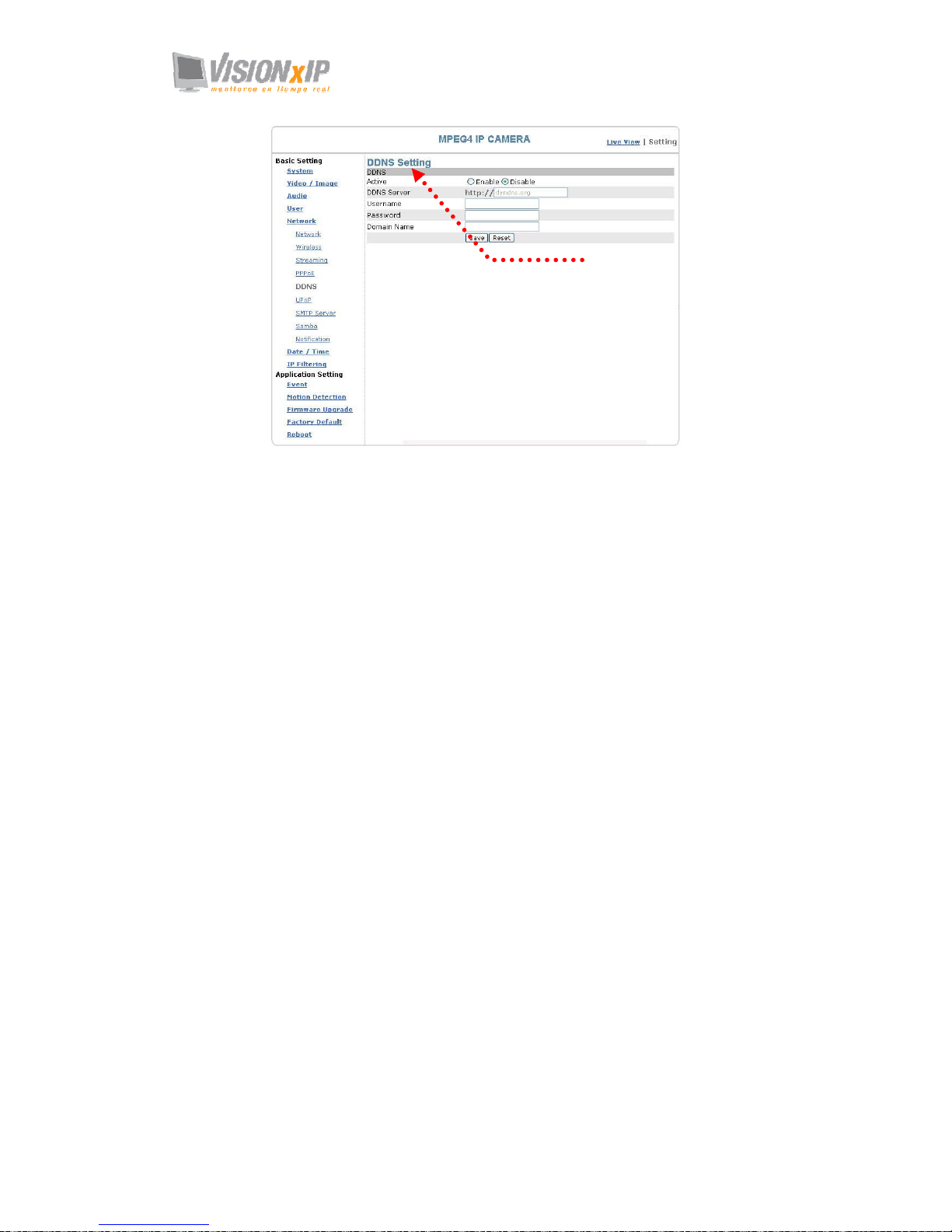
Basic Setting > Network > DDNS (Dynamic Domain Name Server
Setting)
The IP address (Ex. 210.168.0.22) is like a telephone number, while the website
address is like a name in an address book. The DDNS allows the user to access the
website by entering the name of the website without memorizing a bunch of cold
numbers.
When you apply for an Internet service, you will have at least one IP address from
your ISP that is either fixed or dynamic. Most of the ADSL service providers will
give you a dynamic IP for ADSL environments, which means your IP address will
constantly change each time you connect to the Internet. As a result, users from
WAN environments will have much difficulty finding the correct IP address. The
DDNS (Dynamic DNS service) is created for exactly this kind of moment. By
updating your WAN IP address each time you connect to the Internet, the DDNS
helps you locate your website and access your website easily. You can find a lot of
free DDNS service providers on the Internet, such as www.no-ip.com and
www.DynDNS.org.
Some gateway-routers can directly communicate with DDNS. In this case, you may
directly enter your DDNS account on the setting page in the Internet router, and then
the router will update your WAN IP status whenever it is changed and report to the
DDNS. If your router does not support direct communication with the DDNS, you can
download a small application program on the DDNS service page to help you update
your WAN IP.
Item Description:
Active: enables/disables DDNS
DDNS Server: currently we only support http://dyndns.org. This is a free domain
name server provided by DynDNS. You may log on this website for relevant
information and apply for free domain names.
Username: your account for the domain name you applied for
Password: your password for the domain name you applied for
Domain Name: the domain name you applied for.
Page 43
Page 44
Mail: [email protected]
Web: www.visionxip.com
44
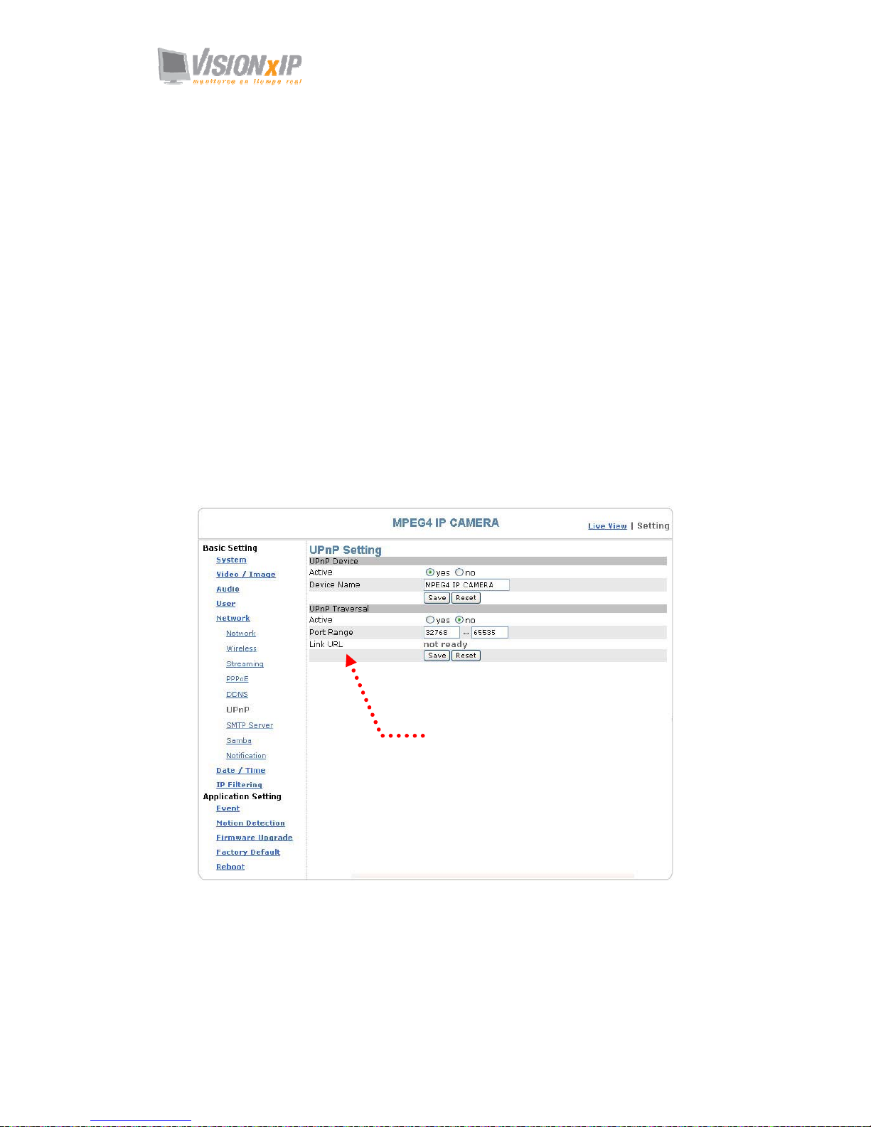
Basic Setting > Network > UPnP (Universal Plug and Play)
If you connect your camera to a router, IP allocator, or wireless AP, your camera will
possibly be blocked by the NAT and can’t be located on the Internet. To penetrate the
firewall, activate the supportive item- UPnP. The Link URL shows the external IP
address and the port of the router. Enter the IP address in the Internet Explorer to
penetrate the NAT.
Basic Setting > Network > UPnP > UPnP Device
Active: yes (enable)/no (disable)
Device Name: the name of the UPnP device
Basic Setting > Network > UPnP > UPnP Traversal
Active: yes (enable)/no (disable)
Port Range: the range of the usable ports, from 32768 to 65535 as default
Link URL: Uniform Resource Locator, the web address
Click “Save” to confirm when you finish.
UPnP setting
Web address
Page 45
Mail: [email protected]
Web: www.visionxip.com
45
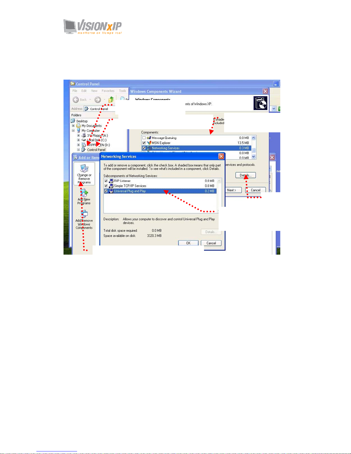
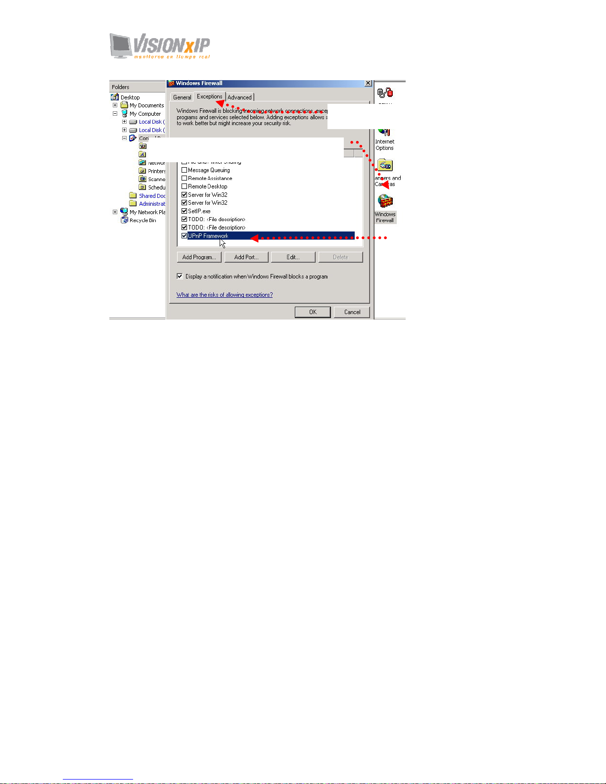
To activate the UPnP function in Windows OS:
Ex: Windows XP:
1. Windows component installation.
2. Open Windows firewall option
1. Click Control Panel
2. Click Add/Remove Programs
3. Click Add/Remove Windows Components
4. Click Networking
Services
5. Click Detail
6. Check UPuP User
Interface
Page 46
Mail: [email protected]
Web: www.visionxip.com
46
1. Click Windows Firewall in the Control Panel
2. Click Exceptions
3. Check UPnP Configuration.
Page 47
Mail: [email protected]
Web: www.visionxip.com
47
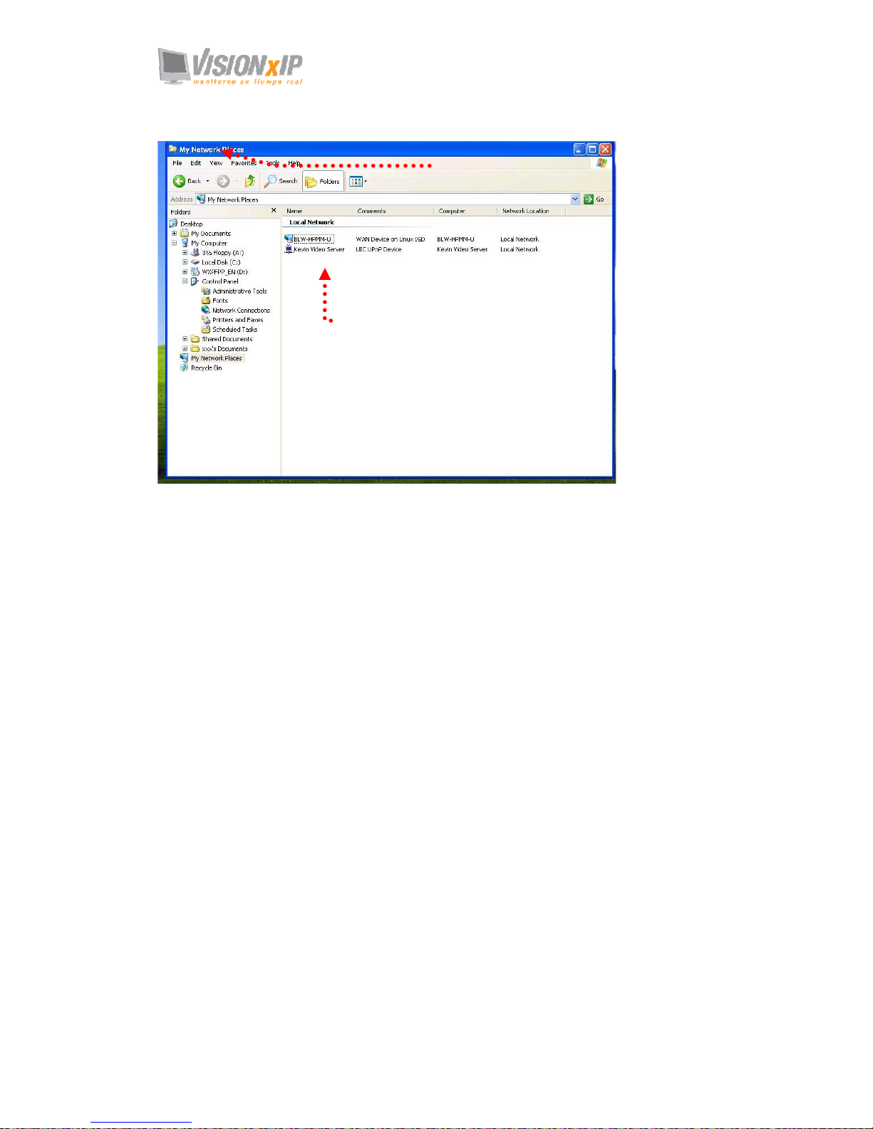
3. View the connection device using “My Network Place”
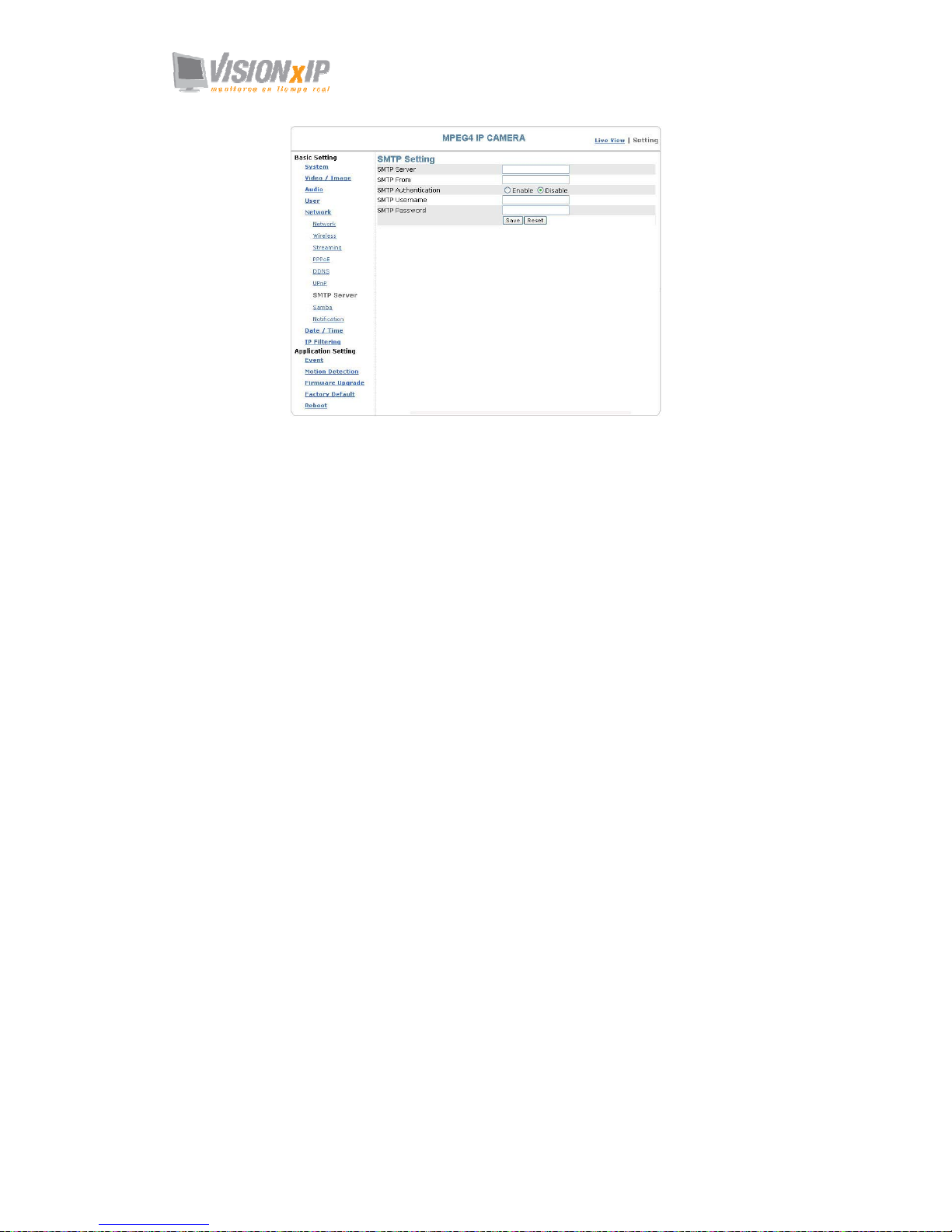
Basic Setting > Network > SMTP Server (mail server setting)
This camera is able to transmit images to a particular email address when a motion
detection event occurs or a sensor is triggered. To use this function, a mail server
setting for the camera is required.
Enter the following information in sequential order to complete the setting:
z SMTP server: the SMTP server IP address.
z SMTP From: the email of the sender, i.e. [email protected]
z SMTP Authentication: enables/disables
z User name: the SMTP server username.
z Password: the password of the SMTP server.
z Select “SAVE” to save the setting.
1. Open “My Network Place”
2. The LAN camera appears.
Double-click to access the main page.
Page 48
Page 49
Mail: [email protected]
Web: www.visionxip.com
49
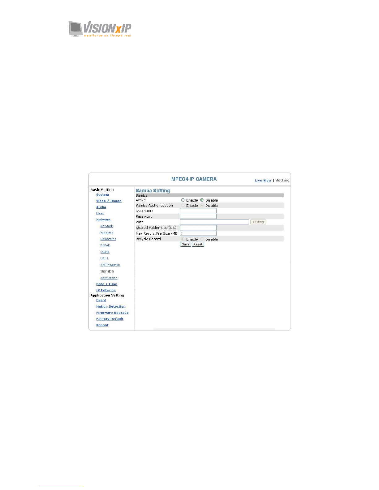
Basic Setting > Network > Samba
This camera is able to upload the snapshots to a specified shared folder when an event
is triggered. To use this function, a Samba setting is required.
Options:
Active: Enable/Disable
Samba Authentication: Enable/Disable
Username: the username
Password: the password
Path: specify the IP address of the computer you want to share with and the file name,
i.e. 192.168.0.X/xxx
Shared Folder Size (MB): the total capacity of the folder. Always remember to set the
size of the folder to avoid exhaustion of disk capacity.
Max Record File Size (MB): the upper limit of the record file size. The size should
not exceed the total capacity of the folder.
Samba setting
Page 50

Mail: [email protected]
Web: www.visionxip.com
50
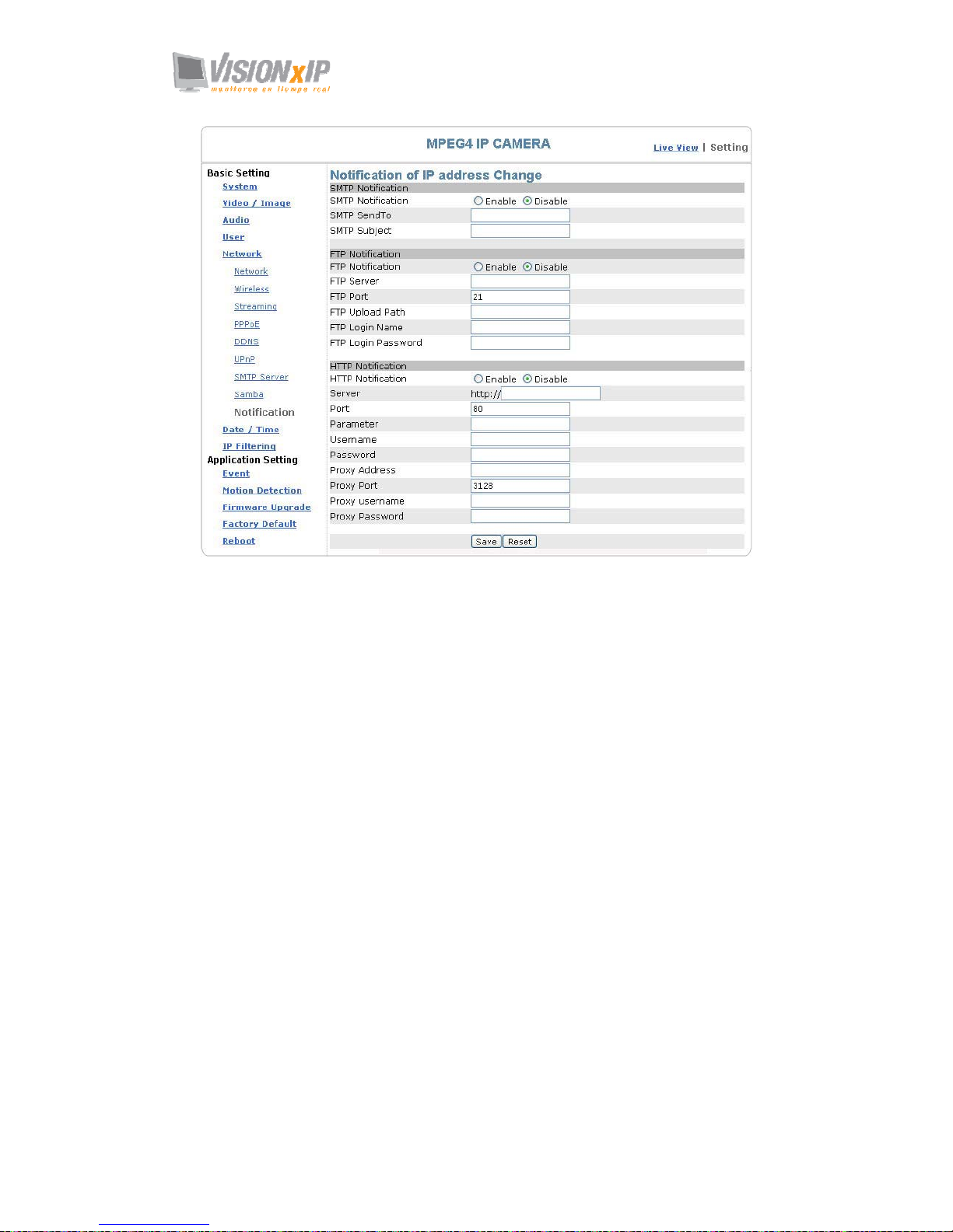
Basic Setting > Network > Notification Of IP Address Change (IP
address change notice)
This setting is not necessary for a fixed IP. For a dynamic IP, you need to update the
IP address every time you connect to the Internet to access the camera. This setting
allows you to update the IP address by the automatic notification of IP address change.
Choose one of the following three notice options to update the IP address:
1. Notification via SMTP mail server
Basic Setting > Network > Notification of IP Address Change > SMTP
Notification
SMTP Notification: notification via SMTP mail server
SMTP SendTo: the recipient, i.e. [email protected]
SMTP Subject: mail subject
Select Save to complete and activate your settings.
2. Notification via FTP server
Basic Setting > Network > Notification of IP Address Change > FTP
Notification
FTP Server: FTP Server name.
FTP Port: FTP port. The default setting is 21 (recommended).
FTP Upload path: the path to upload files.
FTP Login name: the name to log in the FTP.
FTP Login Password: the password to log in the FTP.
Select Save to complete and activate your settings.
3. Notification via HTTP server
Basic Setting > Network > Notification of IP Address Change > HTTP
Notification
Server: the address of the server, i.e. http://.
Port: the port to access HTTP. The default setting is 80 (recommended).
Parameter: the setting of the parameters, refer to the installation setting of your
HTTP server.
Refer to the installation setting of your HTTP server for the setting of the
parameters (such as Username, Password, and Proxy).
Select Save to complete and activate your settings.
Page 51
Page 52
Mail: [email protected]
Web: www.visionxip.com
52
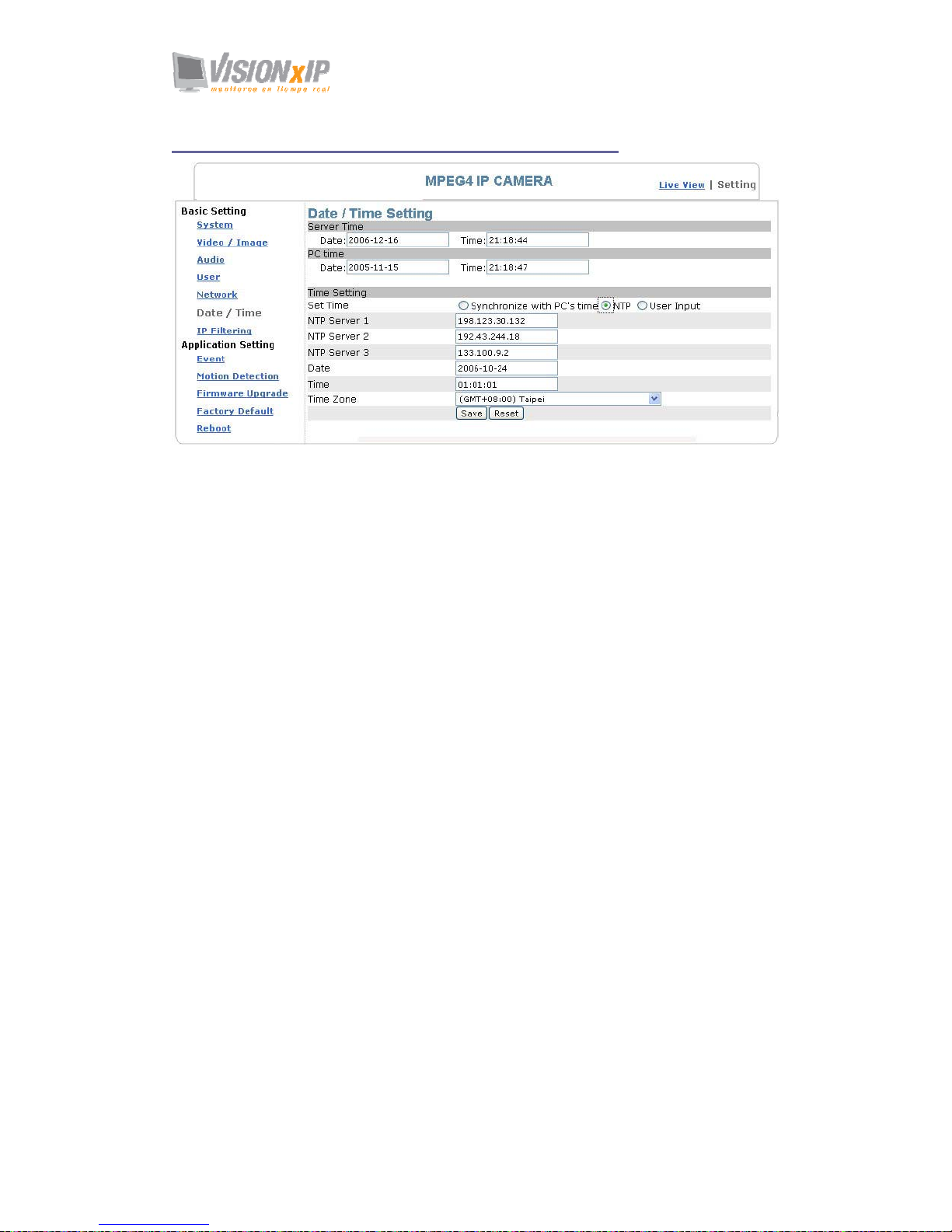
Basic Setting > Date/Time (date/time setting)
Date/Time setting
Basic Setting > Date/Time > Server Time (the date/time of the server)
Basic Setting > Date/Time > PC Time (the date/time of your PC)
Basic Setting > Date/Time > Time Setting (date/time setting)
There are three ways to synchronize the time.
1. Synchronize the time with PC’s time:
The preset method of time synchronization of the camera time with your PC
time.
2. Get Time from an NTP server: synchronize the time with the NTP
(Network Time Protocol)
z Click on the “NTP” Button
z Enter the NTP server’s IP address.
z Press “SAVE” to activate it.
The camera will update its time once obtaining the NTP time.
Note: The default NTP servers are:
A. NTP Server 1: 198.123.30.132
B. NTP Server 2: 192.43.244.18
C. NTP Server 3: 133.100.9.2
3. Change the time manually:
z Click the “User Input”.
z Select the format of date display, i.e. “yyyy/mm/dd” format.
z Select the format of date display, “hh:mm:ss” by 24 hours format.
z Select the time zone.
z Select “Adjust” to adjust time.
Page 53
Mail: [email protected]
Web: www.visionxip.com
53
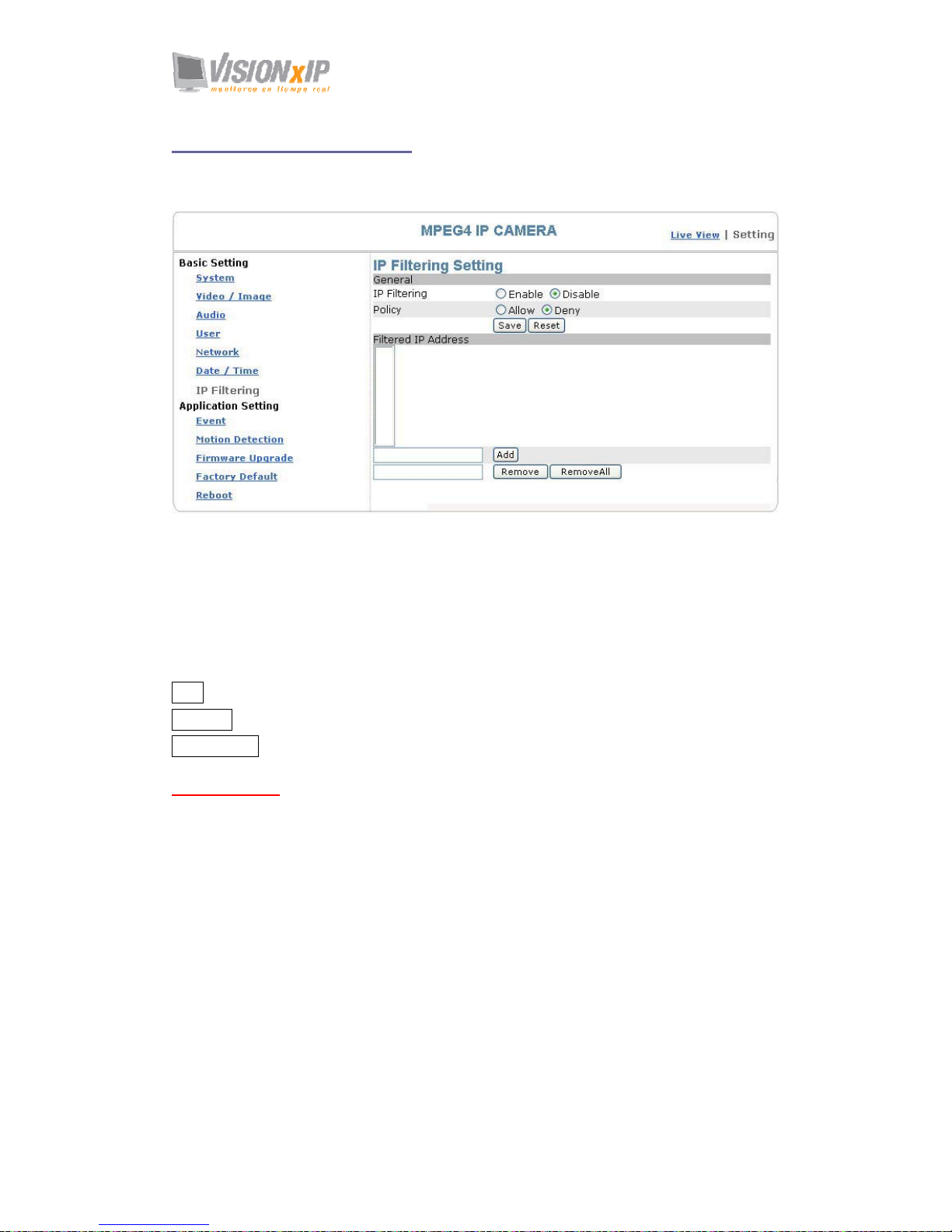
Basic Setting > IP Filter
This function filters IP addresses and is able to allow or deny visits from particular
addresses/target addresses.
IP filter setting
Basic Setting > IP Filter > General
IP Filtering: enables/disables the IP filter
Policy: allows/denies access
Basic Setting > IP Filter > Filter IP Address (Overview of the set IPs)
Add: enter the IP address you want to allow or deny the access of in the front field.
Remove: removes a set IP addresses
Remove All: removes all the set IP address
Special Attention
Setting rules:
1. Actions that may cause a limited connection are to be denied.
2. Improper use of this function may cause disconnection from Internet. You might need
to use hardware reset to reset to the factory default. Please refer to the “Factory
Default” for details.
Page 54
Mail: [email protected]
Web: www.visionxip.com
54
Application Setting
Application Setting > Event (event trigger setting page)
This camera is equipped with intelligent security management functions. It ensures
security monitoring by allowing user to define “trigger events” based on particular
times and situations, and sets the camera respond to the event.
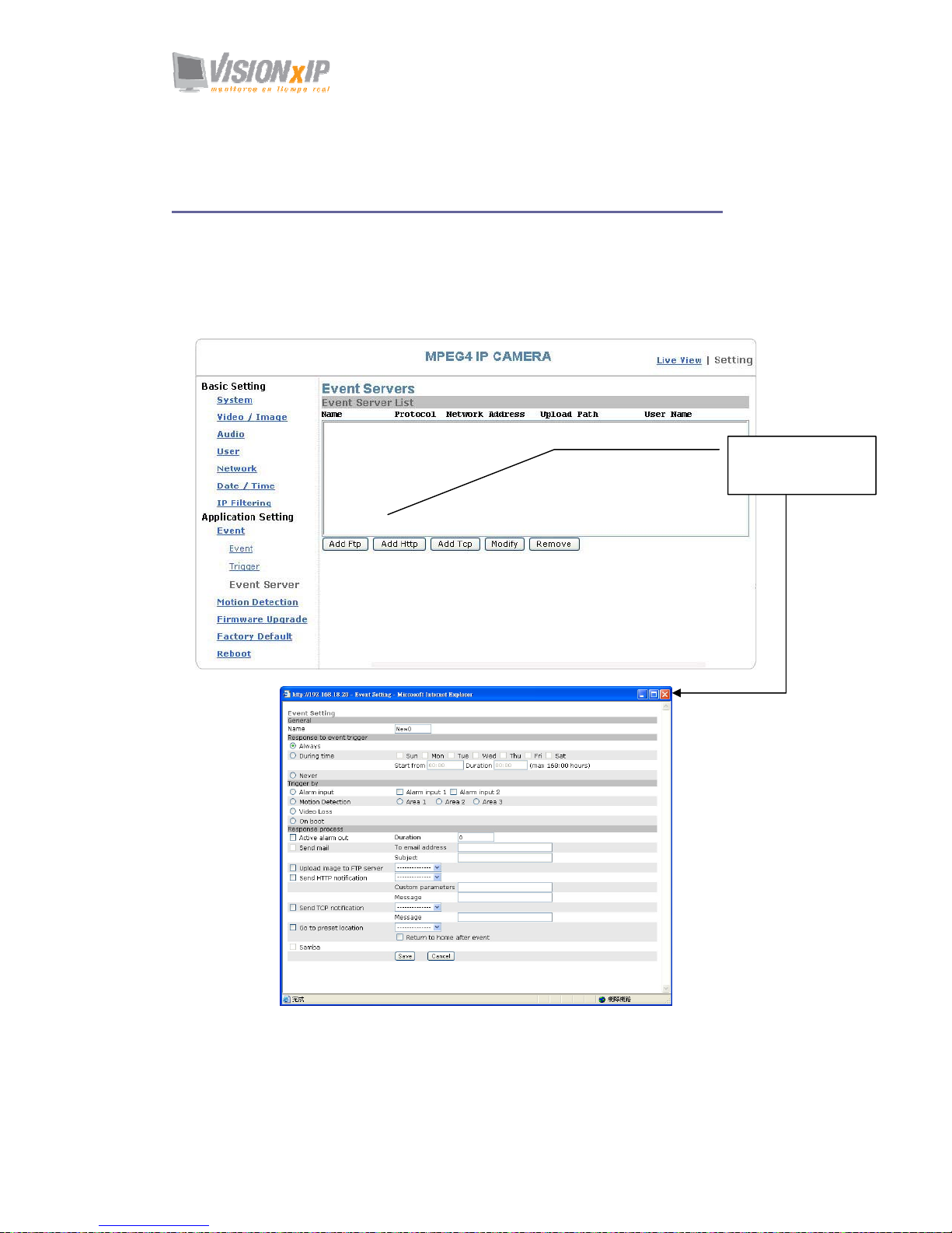
Application Setting > Event > Event List (trigger event setting)
Click Add Event to
enter the trigger event
setting
Page 55

Mail: [email protected]
Web: www.visionxip.com
55
Add Event : Add Event setting page
Options:
• General:
Name: Name the trigger event here.
• Response to event trigger: the time setting of the trigger event
Always: Always monitoring
During time: Check the date you want to monitor (Sun~Sat) and the duration of
monitoring here. For example, if you want to set the camera to
monitor from 7 pm after work to 7 am next morning from Monday
to Friday, check the boxes from Monday to Friday, enter “19:00” in
the “Start From” field, and enter “12:00” in the “Duration” field.
Never: Do not set the time.
• Trigger by: sources of trigger events (Note: You can only set one trigger event once.)
Alarm input: The alarm is triggered by the security equipment connected from the
DI terminals behind the machine, such as door/window detectors,
infrared sensors.
Motion
Detection:
The alarm is triggered when motion is detected. The camera will
send an alarm when any objects appear in the set detection area.
Video Loss: The alarm is triggered by video loss. The camera will send an alarm
when there is no video transmission due to camera sabotage or other
reasons.
On boot: The alarm is triggered by reboot. The camera will send an alarm
when the system is rebooted due to power shortage, sabotage, or
other reasons.
• Response process: trigger event response (Note: Multiple selections are available)
Active alarm
out:
An event is detected by the security equipment connected from the
DI terminal behind the machine, such as high-decibel alarms, light
projectors. You can set the alarm duration in the “Duration” field.
Send mail: The alarm will be sent to you by email.
Send HTTP
notification:
The alarm will be sent to the HTTP server you specified. To use this
function, set the coordinative HTTP server in the Event Server
setting page in advance.
Send TCP
notification:
The alarm will be sent to the TCP Server you specified. To use this
function, set the coordinative TCP server in the Event Server setting
page in advance.
Go to preset
location:
The camera will move to the location you specified when a trigger
event occurs. To use this function, set the present location of the
camera in the main page in advance.
Return to
home after
event:
The camera will move back to the home position (center)
Click Save to save and activate your settings when you completed setting.
Page 56
Mail: [email protected]
Web: www.visionxip.com
56
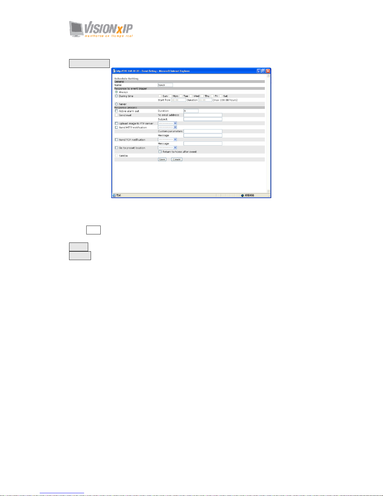
Add Schedule: Add Schedule setting page
The Add Event setting page and the Add Schedule setting page are basically the same
except that the Add Schedule setting page does not have the option “Trigger by” to
indicate the sources of the trigger event.
Click Save to save and activate your settings when you complete setting.
Delete: delete the event cluster setting.
Modify: modify the event cluster setting.
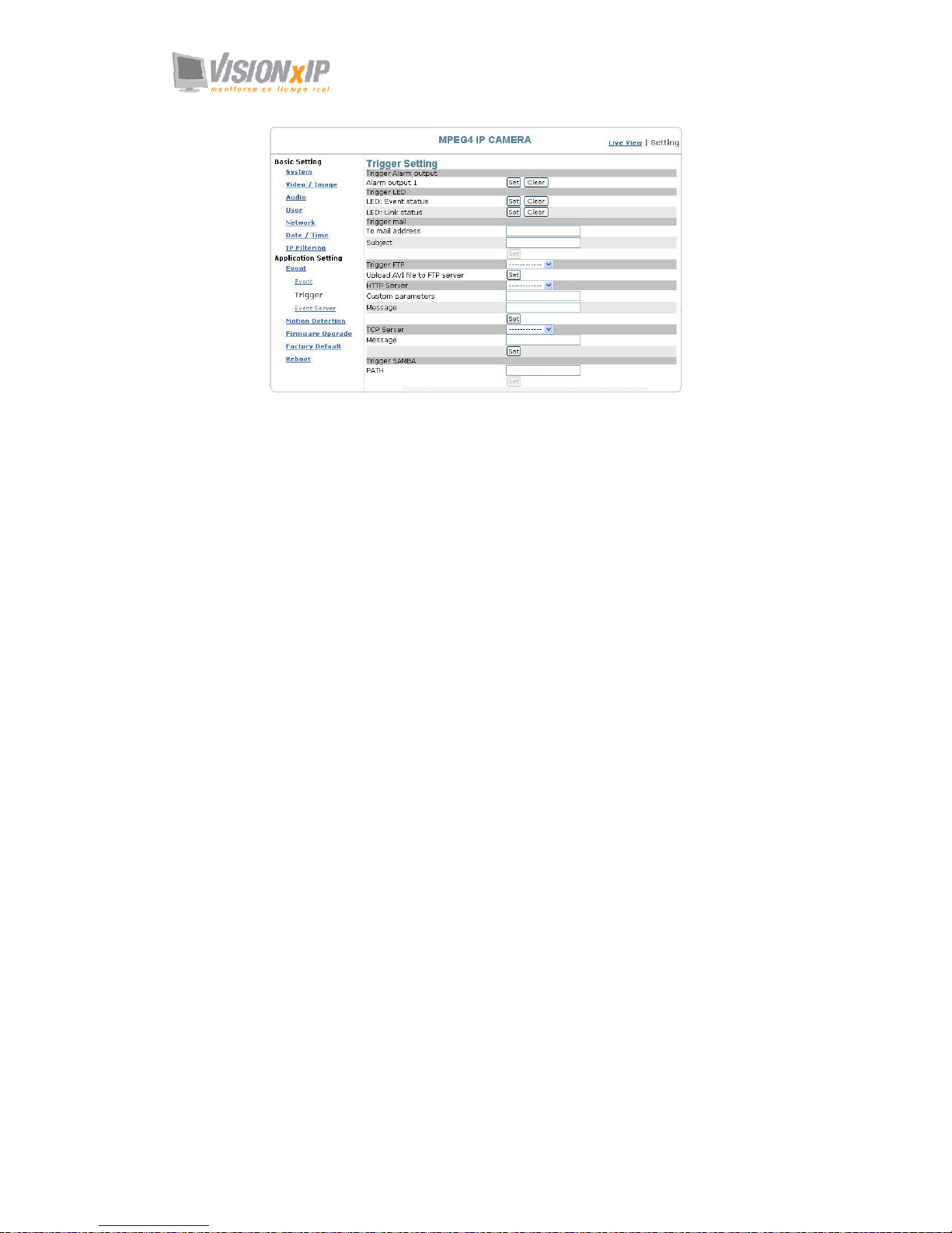
Application Setting > Event > Trigger (manual test of trigger
response)
Whenever the camera detects abnormal events during the scheduled time, it will
automatically respond by performing trigger response. There are 3 types of trigger
responses: alarm sending, LED status indicator flash, and emailing the alarm or
recorded image to the specified server. To use this function, enter the server
information by accessing Application Setting > Event > Event Server. You may
perform manual test as specified in this section once you complete the setting to
ensure that all functions are working properly.
Page 57
Page 58
Mail: [email protected]
Web: www.visionxip.com
58
Trigger Alarm output: Alarm output
Click “Set” to trigger the alarm. Click “Clear” to stop the alarm.
Trigger LED: LED indicator display
LED: Event status: click “Set” to turn on the LED event status indicator.
Click ”Clear” to turnoff the indicator.
LED: Link status : click “Set” to turn on the LED Link status indicator. Click “Clear”
to turnoff the indicator.
Trigger mail: Sending mail
Click “Set” after you enter the email address and subject to test the integrity of the
sent mail.
Trigger FTP: Sending AVI file to FTP Server
Upload AVI files to FTP server to test the file integrity.
HTTP Server: Sending message to HTTP Server
Upload message to HTTP server to test the message integrity. Enter the message in
the “Message” field. You may go to Application Setting > Event > Event Server to
make a complete custom parameters settings.
TCP Server: Sending message to TCP Server
Enter the message in the “Message” field.
Trigger SAMBA: Sending message to Samba shared folder
Path: Enter the path of the shared folder in your PC.
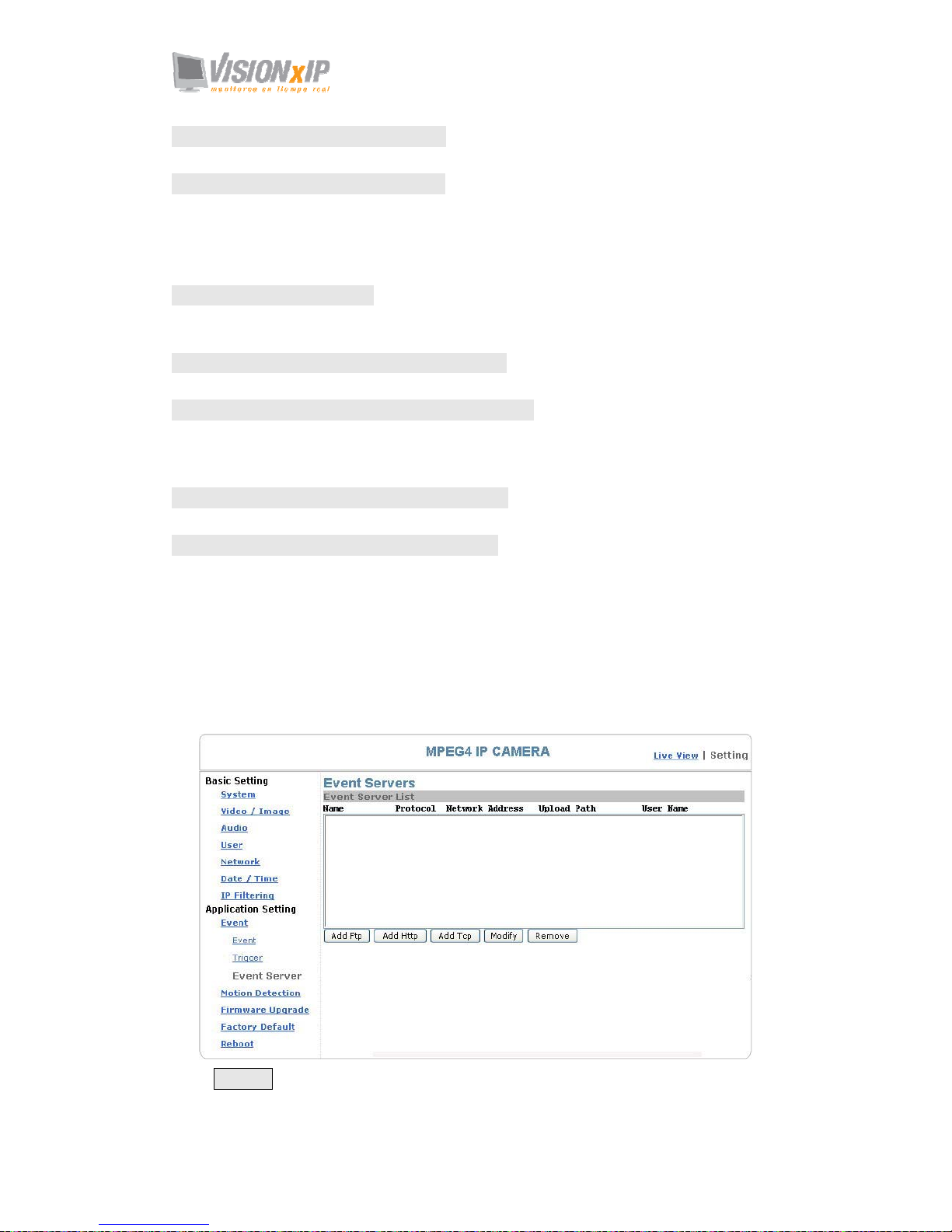
Application Setting > Event > Event Servers (setting for uploading
trigger event file to the server)
Here you can perform a complete setting for uploading files to the server. Please set
servers (SMTP, FTP, SAMBA…etc) in the Event Server setting by the instructions
below:
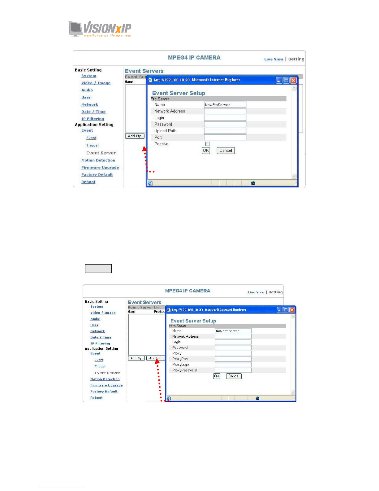
Click Add Ftp to go to the setting page and enter the information of the FTP server
you specified.
Page 59
Mail: [email protected]
Web: www.visionxip.com
59
Name: the name of the FTP
Network Address: IP address of the FTP
Login: Log-in name
Password: Log-in password
Upload Path: Uploading path
Port: Port
Passive: Check to set the FTP status as passive
Click Add Http to go to the setting page and enter the information of the HTTP server
you specified.
Name: HTTP name
Network Address: HTTP IP address
Login: Log-in name
Password: Log-in password
Add FTP setting page
Add HTTP setting pa ge
Page 60

Page 61
Mail: [email protected]
Web: www.visionxip.com
61
ProxyPort: Proxy server port
ProxyLogin: Proxy server log-in name
Proxy Password: Proxy server log-in password
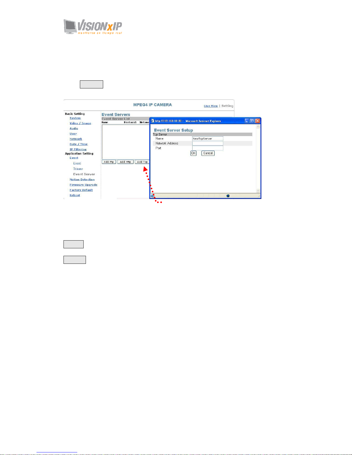
Click Add Tcp to go to the setting page and enter the information of the TCP server
you specified.
Name: TCP server name
Network Address: TCP IP address
Port: TCP port
Modify: Modifies the setting value
Remove: Removes the setting value
Add TCP setting page
Page 62
Mail: [email protected]
Web: www.visionxip.com
62
Application Setting > Motion Detection
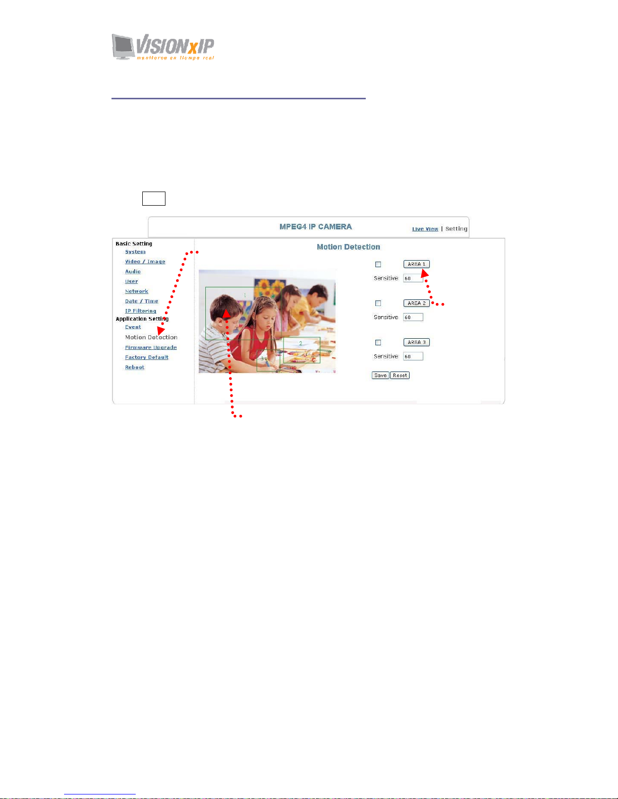
You can open the setting frame by clicking on the area to monitor. To move area to
monitor, drag the area with your mouse; to adjust the size of the frame, drag the arrow
to adjust after you move the mouse to the edge of the area and left-click; There are 3
frames available for setting. You may adjust the sensitivity of the area by entering the
degree of sensitivity in the “Sensitive” field. “1” is least sensitive, ”100” is extremely
sensitive.
Select Save to complete and activate your settings.
Motion detection setting
Setting frame
Area setting
Page 63
Mail: [email protected]
Web: www.visionxip.com
63
Application Setting > Firmware upgrade
Contact your dealer for more information about firmware upgrade. The sales
representative will transmit the latest version to you via e-mail. When you receive the
firmware, decompress the file (uImage.gz) to your PC and follow the steps below to
execute the upgrade.
Important! Read Carefully!!
1. Close all active applications on your PC.
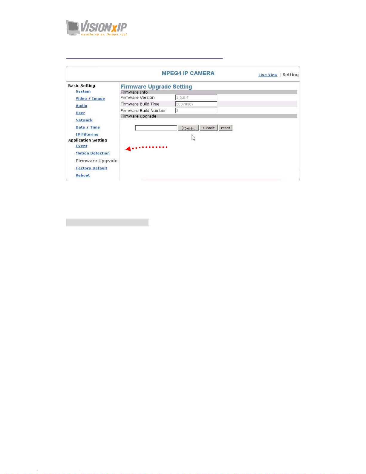
2. Select “Firmware Upgrade”
3. The Firmware Upgrade Setting page appears.
Firmware upgrade page
Page 64
Page 65
Mail: [email protected]
Web: www.visionxip.com
65
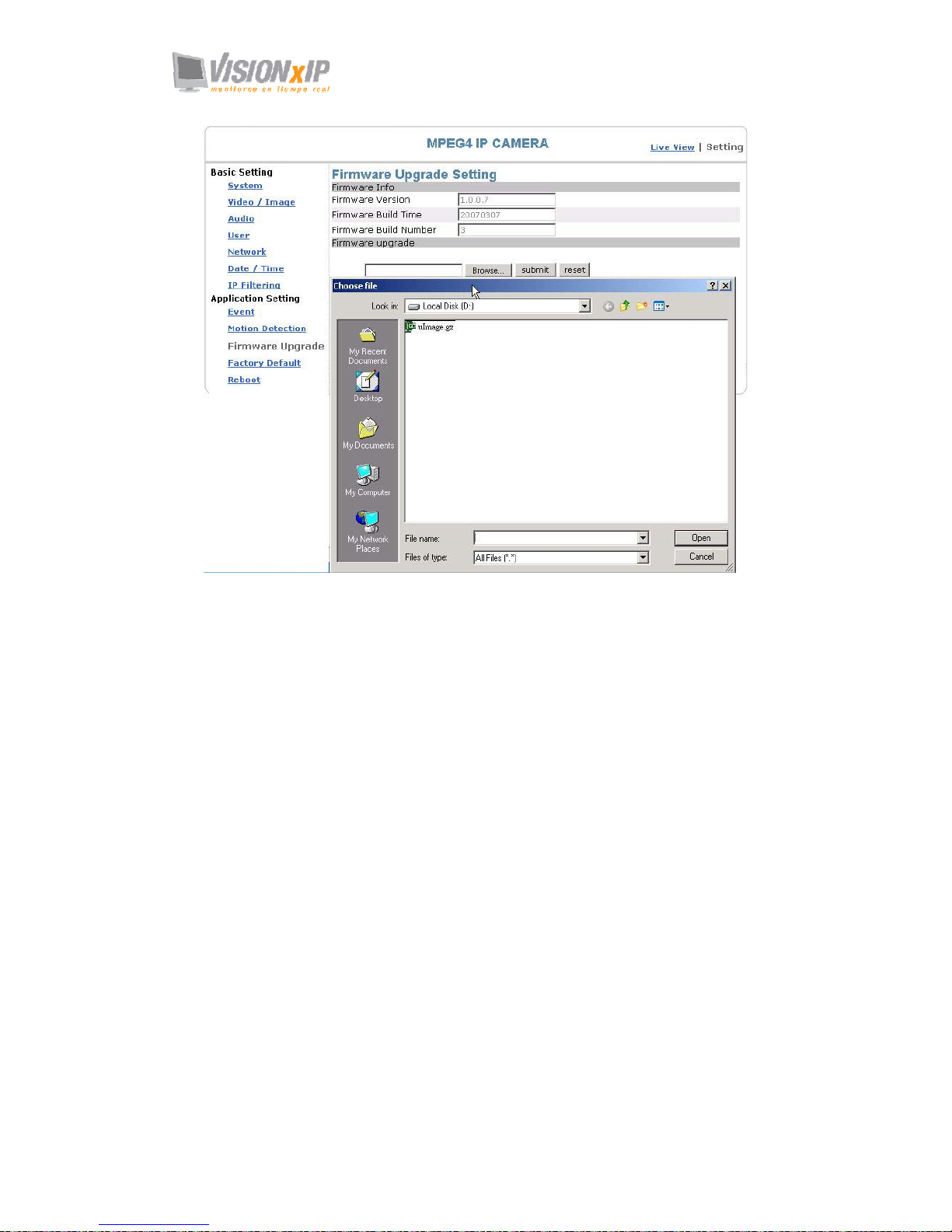
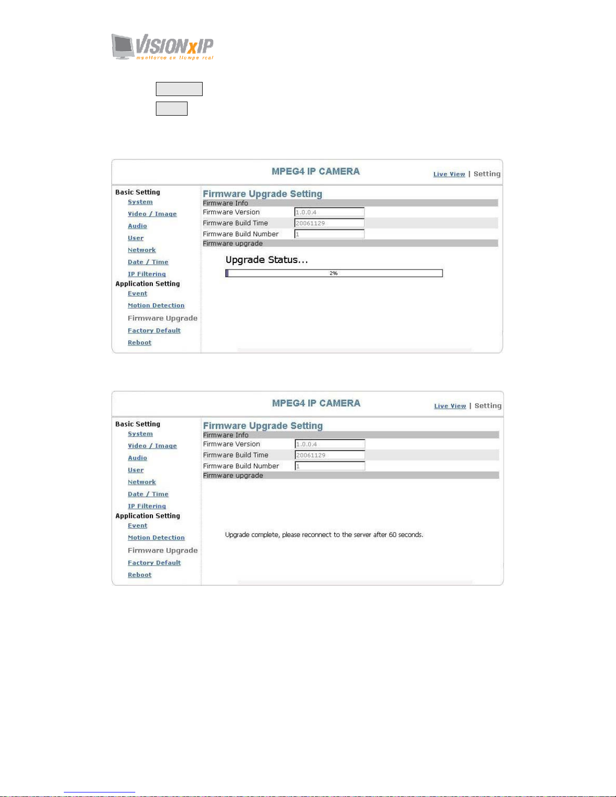
4. Click Browse… to select the location where the firmware file is stored.
5. Click submit.
6. The auto upgrade runs.
The Upgrade Status shows the progress of the upgrade.
When the firmware upgrade has been completed, the machine reboots automatically.
Reconnect to the server after 60 seconds.
Note: The new firmware is burned into the Flash ROM during the upgrade, so you
must take care during the process and make sure it is not interrupted during the
operation. The system may be damaged seriously and need to be returned to the
factory for repair if the power cable is removed or becomes loose during the upgrade.
Firmware upgrading in a wireless network environment is not recommended because
unstable packet transmission may bring about loss of data.
When the firmware upgrade has been completed, you don't need to restart the camera
manually. The camera will reboot automatically after 60 seconds (Reboot OK). Then
open the IE browser and key in the IP address (The original IP address remains
undeleted).
Page 66
Mail: [email protected]
Web: www.visionxip.com
66
Application Setting > Factory Default
You can use this function to reset to factory default, but all changes, including the IP
address, you have made are deleted.
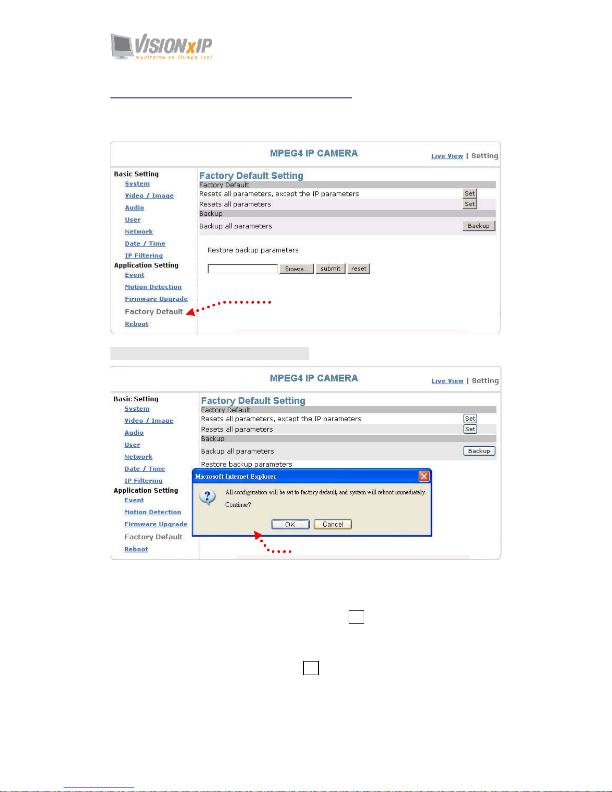
Factory Default: Reset to factory default.
Resets all parameters, except the IP parameters:
You can use this function to reset to factory default. All changes you have made are
deleted but the IP address and all settings relevant to networking remain valid,
including cable and wireless network settings. Click Set to complete the reset.
Resets all parameters:
You can use this function to reset to factory default. All changes, including the IP
address, you have made are deleted. Click Set and a warning window appears to ask if
you really want to reset to factory default. Click “OK” to complete the reset.
Reset to factory default
Warning dialog for rest to factory default
Page 67
Mail: [email protected]
Web: www.visionxip.com
67
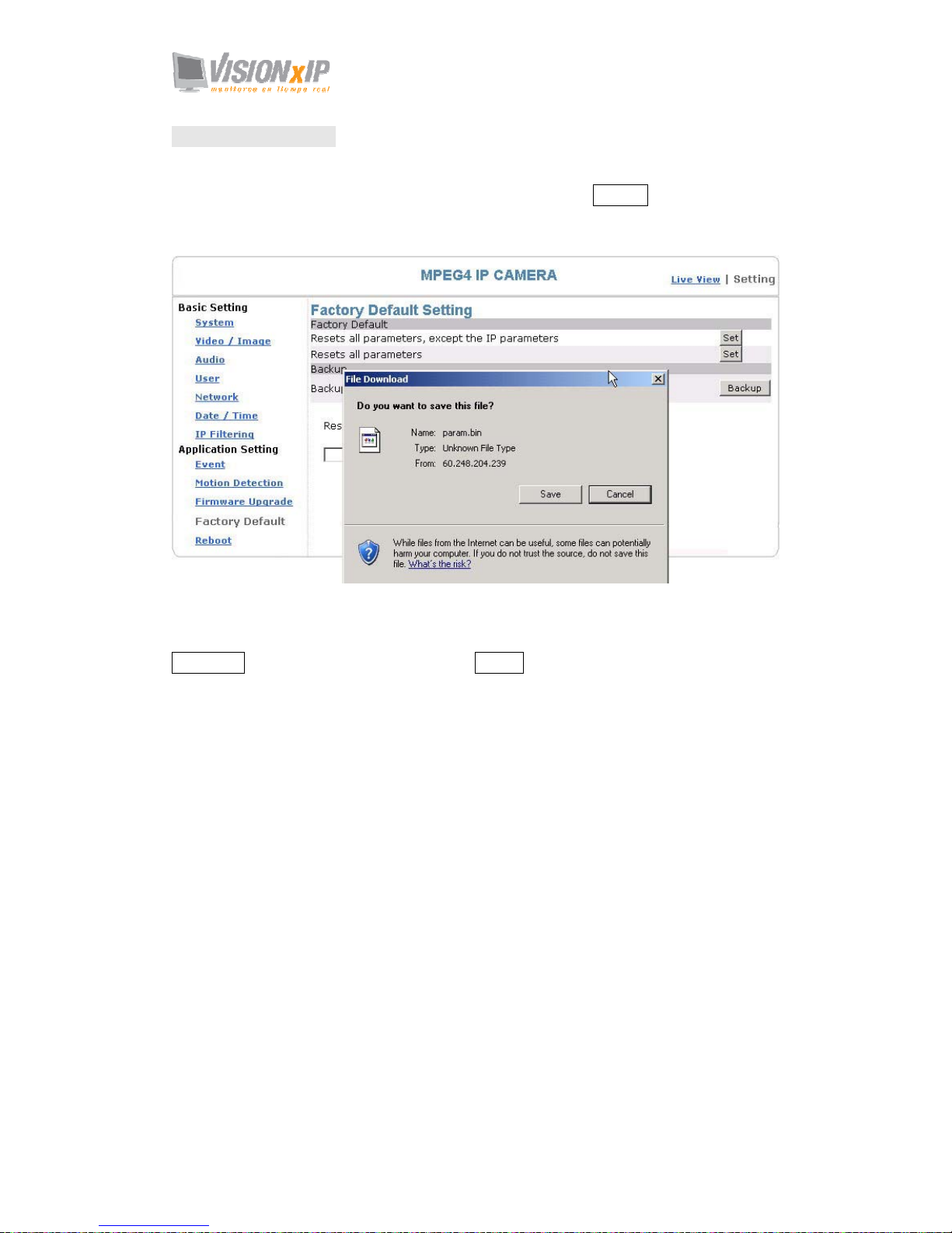
Backup: Data backup
Back all parameters:
Back up all changes you have made. When you click Backup, a file download
window appears. Back up the file named param.bin (Attention: Don't change the file
name; otherwise, the backup may fail.)
File backup
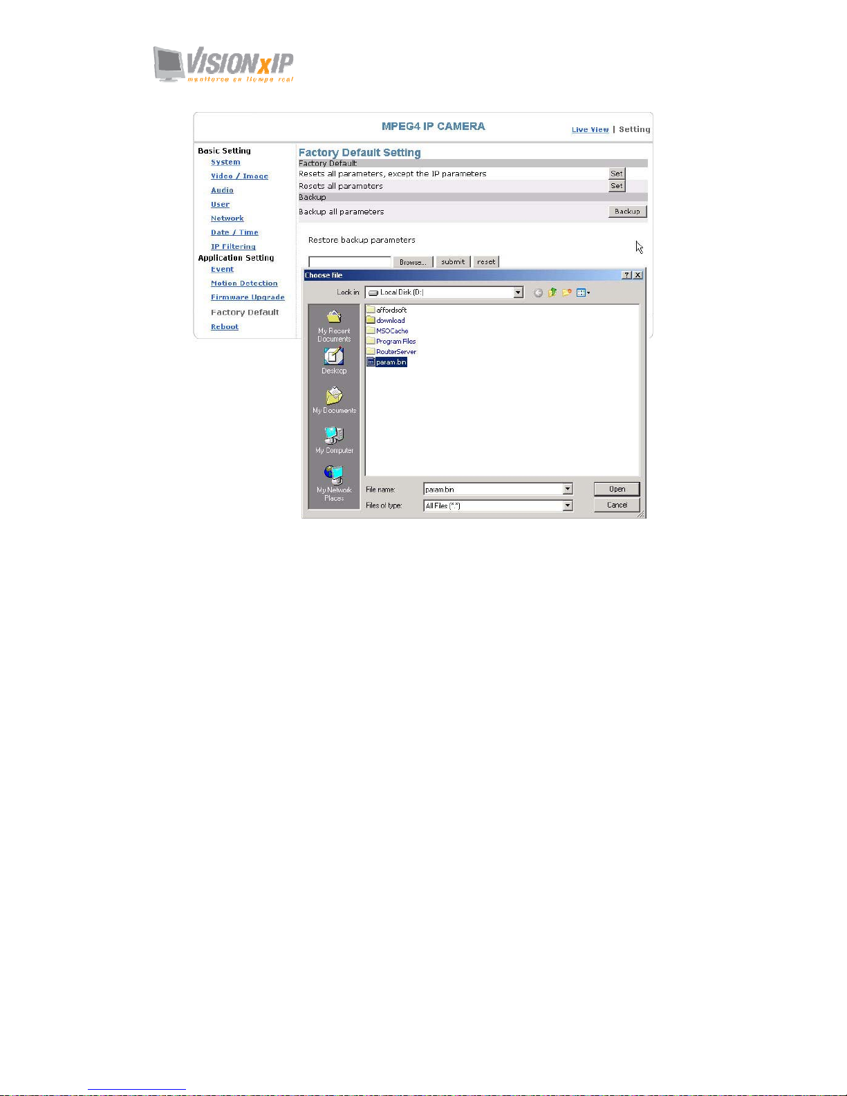
Restore backup parameters:
You can select this function to restore the changes you have made. To do this, click
Browse… to select a backup file and click submit to confirm the restoration.
Page 68
Page 69
Mail: [email protected]
Web: www.visionxip.com
69
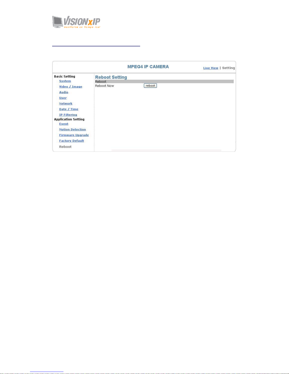
Application Setting > Reboot
You can enable this function for the camera to reboot automatically.
Page 70

Mail: [email protected]
Web: www.visionxip.com
70
Attachment A: Bandwidth Estimation
Since the FPS is dependent on the bandwidth of the camera, the relationship between
the size of an image file and the bandwidth is always the major concern of the system
construction engineer.
The table below shows the relation between the resolution and size of an MJPEG file
in the NTSC system. Please note that the values in the table are for reference only,
because the size of an image file is closely related to the complexity of the
environment and the actual situation of the place being monitored.
Image Resolution Average range of Data Sizes
176 x 122 (QCIF) 20 – 40k bit
352 x 240 (CIF) 40– 200k bit
640 x 480 (VGA) 180 – 400k bit
704 x 480 (D1) 200 – 530k bit
Ex.: The transmission speed on the Internet is 2fps under 352 x 240, i.e. 40k*2=80k to
200*2=400k per second. It is suggested to apply for 512K "upload" bandwidth.
Note 1: What the camera needs at the client end is the “upload” bandwidth. However, most
ISPs in Taiwan provide download bandwidth that is wider than the upload
bandwidth. Therefore, symmetrical bandwidth is a good choice for users who need
wider upload bandwidth. Ex. download/upload = 521K/512K
Note 2: 32 kbps to 64kbps is required for transmission of audio signals.
Page 71
Mail: [email protected]
Web: www.visionxip.com
71
Attachment B: Troubleshooting and FAQs
Question Answer and Solution
Function
What encoder and decoder
are used by the camera for
sounds and images?
The camera uses MJPEG or MPEG4 compression technology to
provide quality images. MJPEG is a standard image compression
technology applicable to different browsers without the need to
install additional software. MPEG4 is a next-generation image
compression standard and can provide high image quality at low
bandwidth.
The sound decoder uses PCM (Stereo, 16bit, 8kHz) compression
technology.
How many users are
allowed to view the camera
simultaneously?
The maximum number of viewers depends on the bandwidth of the
client accessing the camera. About 5~6Mbps are used to process
data of the camera, so the maximum number of viewers changes in
proportion to FPS and the resolution of the image. Obviously, the
higher the number of viewers, the lower the performance at each
client end.
Is it possible to catch the
image from the camera in a
real-time manner?
Yes, you can use the snapshot function from the main control page.
Camera Installation
Can the camera be used
outdoors?
The camera is not waterproof, so a special waterproof cover must
be available for outdoor use. Please note that the waterproof cover
may affect the built-in pickup function of the camera.
Link LED does not light
up.
• Check that the attached standard transformer is not damaged.
Plug the power cable and reboot the machine.
• If the problem remains, contact your dealer for help.
What network cable is used
for the camera?
The camera uses a 10 or 100 Base-T Category 5 UTP network
cable.
How to install and operate
the camera behind a
firewall?
If you have a firewall in your network environment, please select
HTTP mode (Port80). Generally the port 80 is always open for the
browser to access the Internet.
What are the username and
password for the first use
and after reset to factory
default?
Username = root
Password=root.
Please change your password immediately after entering the system
to ensure information security.
I forgot the username and
password I used for the
setting. What should I do?
Please proceed as follows:
1. Hold the Reset button for 4 seconds after booting to reset the
password to preset.
2. Change the username and the password.
I forgot the IP address of
the camera. What should I
do?
Use IP Finder to locate the IP address of the camera.
Please connect the camera and the PC on which the IP finder is
executed to the same hub.
IP Finder cannot find the
camera.
• When the camera still can’t be located over 1 minute, re-activate
the camera.
• Do not connect the camera to more than one router. The IP
Finder will not be able to detect the camera.
• If the IP of PC on which the IP Finder is executed is not correctly
set, the IP Finder will not be able to locate the camera. Please
Page 72
Mail: [email protected]
Web: www.visionxip.com
72
confirm that the IP address has been properly set.
• The anti-virus applications on the PC or the firewall might block
the IP Finder from execution. If you can not execute the IP
Finder, please disable your anti-virus applications or firewall.
Internet Explorer does not
display the camera screen
correctly.
Please be sure that the version of your Internet Explorer is 6.0 or
later. Should you have any difficulties, please log on the Microsoft
website to update your browser.
Microsoft website: http://www.microsoft.com/windows/ie.
IP Finder cannot store
network parameters.
• Do not use spaces. Use underline “_” or dash “-“.
• Your connection might have problems. Please ensure that the
network parameters and the camera connection are correctly set.
Access to Camera
I cannot enter the login
screen and camera page
from Internet Explorer.
What should I do?
• The IP address of the camera is possibly being used by another
PC or device. Please disconnect the network cable from the
camera and execute PING to confirm if the IP address has been
used.
• It is possibly due to the network cable. Please use the cross-line
network cable to connect the PC and the camera, and see if the
log-in screen appears.
• Be sure that the network connection and the settings are properly
configured.
• Be sure to enter correct IP address in the Internet Explorer. If you
use dynamic IP address, the address might have been changed
after your last check.
• Internet traffic might slow down the webpage access. Please wait.
• Be sure that you are using http port. The default setting is Port
80. It will be converted to the private camera IP address.
• The port assigned for your camera might not able to access the
Internet. Contact your ISP to acquire a usable port.
• The proxy server might be blocking you from connecting to the
camera. Do not set the proxy server.
• Please be sure that the default gateway address is correct.
• Your router might need Port conversion. Refer to the user manual
of your router for details.
• The package filtering function of the router might have blocked
the access to the external Internet. Refer to the user manual of
your router for details.
• If you are using DDNS, please remember to set the default
gateway and server address.
• If none of the procedures above is working, please reset to the
factory default values and re-install.
• If the problem still persists, there might be some problems with
the product. Contact the dealer who sold you the product for
more help.
No image appears on the
main control screen.
• When using PC to connect to the camera for the first time, a
security warning window will tell you that you need to download
the ActiveX control. When you are using Windows 2000 or
Windows XP, you might need a properly- authorized user
account to install the application
• Network traffic might slow down the video streams. If the video
is extremely slow, select a lower resolution for a lower
bandwidth requirement.
Page 73
Mail: [email protected]
Web: www.visionxip.com
73
Check whether the Active
X control of the camera has
been installed in your
computer.
Select C:\Windows\Downloaded Program Files to check if the file
“Media Viewer Class” is registered. The status bar should
indicate the file has been installed. If you do not see this file, be
sure that your Internet Explorer security is properly set (the default
value is moderate). Re-connect to the camera main page and
download the file again. Incomplete download or installation of the
camera ActiveX control is the major reason for this problem. Check
the security setting of your Internet Explorer. Close and re-open
Internet Explorer, and enter the main page to see if you can log in.
Internet Explorer displays
the following message:
Downloading the ActiveX
control is prohibited under
the current security
setting."
Change the IE security setting to allow downloading unsigned
ActiveX control.
IE→Tools→Internet Options→Security→
Custom Level. Change
"Inactive" to "Tips" for the ActiveX control if required.
The camera can operate
only in the LAN rather in
the Internet environment.
• A firewall mechanism might have been activated. Check the
setting of your system or ask your network administrator. To
access the camera from the Internet, you may need to change the
setting of the firewall.
• Make sure that your camera does not conflict with other servers
on the same LAN.
• Check the router and make sure that its setting allows it to access
your camera from the Internet.
The number of frames
transmitted are less than
the defined value.
• Congestion of the network or objects of the image may affect the
number of frames transmitted. The number of frames may be less
than the defined value when they are transmitted via a congested
network.
• The number of frames transmitted may become less when
multiple users are viewing the video stream.
• The network hub might be another reason for this problem,
especially when multiple camera video streams are viewed
simultaneously.
When the audit function is
activated, the video
streaming area becomes
black or the transmission
becomes slower.
• When you connect your PC to the camera, no sufficient
bandwidth is available to support more frames with the current
resolution of video streams. Reduce the resolution to
QCIF(176x144) or CIF (320x240) and deactivate the audio
function.
• The audio signal needs 32 to 64 kbps of your bandwidth. You can
deactivate the audio function to improve the image quality. Your
Internet service may have not sufficient bandwidth to support
audio transmission.
Images cannot be
transmitted via e-mail or
FTP.
• Make sure the IP address of the gateway and domain server
(DNS) have been defined correctly.
• Where FTP still fails, contact your ISP or network administrator
to check the FTP server.
I can't control the camera
to move up, down, right,
left or to the center or
preset point.
• When communication to the camera stops, click "Refresh" on
your IE browser to refresh the transmission.
• It might be that other users are controlling the movement of the
camera.
• The horizontal/vertical movement of the camera has reached its
limit.
• The horizontal/vertical remote control option of the camera might
have been deselected.
Page 74
Mail: [email protected]
Web: www.visionxip.com
74
I can't control the camera
to move up, down, right, or
left smoothly.
Delay might occur when you are accessing a video stream and
remotely moving the camera horizontally. Where significant delay
is identified when you move the camera horizontally or vertically
deactivate the audio streams and/or reduce the size of the video
stream...
Camera Image Quality
Camera has a problem
focusing.
• The lens might be contaminated with dust, fingerprints, or other
dirt. Use a special cleaning cloth to clean the lens or adjust the
focus manually.
• Focusing might be impossible in some cases. If the object is too
close to the lens, more it away from your camera.
Color of the video stream
is too deep or light.
• Please confirm that the image your are watching has the best
quality. Adjust the setting of your display card (color quality) to
at least 16 bits (24 bits or more are recommended).
• Incorrect camera video setting. You may need to adjust some
parameters, such as brightness, contrast, color, and saturation.
Video stream flashes. • Incorrect power cord frequency may cause flashing of the image.
Confirm that your camera uses NTSC or PAL system.
• The image flashes if the objects are black. In this case, adjust the
illumination brighter around your camera.
This is noise problem
during transmission of the
image.
Noise may be produced if you install your camera at a very dark
place. Adjust the illumination around your camera.
Others
How to reboot my camera? If you only need to re-boot the system and don't want to change any
setting, enter the Setting page and select the Reboot option at the
bottom of the screen. The system will reboot automatically.
I can't replay recorded
files.
Confirm that you have installed Microsoft®’s DirectX 9.0 or above
and use Windows Media Player 9 or above.
NOTE :
This equipment has been tested and found to comply with the limits for a Class B digital device, pursuant
to part 15 of the FCC Rules. These limits are designed to provide reasonable protection against harmful
interference in a residential installation.
This equipment generates, uses and can radiate radio frequency energy and, if not installed
and used in accordance with the instructions, may cause harmful interference to radio communications.
However, there is no guarantee that interference will not occur in a particular installation. If this equipment
does cause harmful interference to radio or television reception, which can be determined b y turning the
equipment off and on, the user is encouraged to try to correct the interference by one or more of the
following measures:
—Reorient or relocate the receiving antenna.
—Increase the separation between the equipment and receiver.
—Connect the equipment into an outlet on a circuit different from that to which the receiver
is connected.
—Consult the dealer or an experienced radio/ TV technician for help.
You are cautioned that any change or modificatio ns to the equipment not expressly approve by the party
responsible for compliance could void your authority to operate such e quipment.
 Loading...