

You May Also Be Interested In:
Part # - 9891019
Item # - XIL-OEH0713JKXPI12
Jeep JK Vehicle Specifi c Hood Mount Bracket (visit
www.visionxusa.com for a full list of vehicle specifi c products)
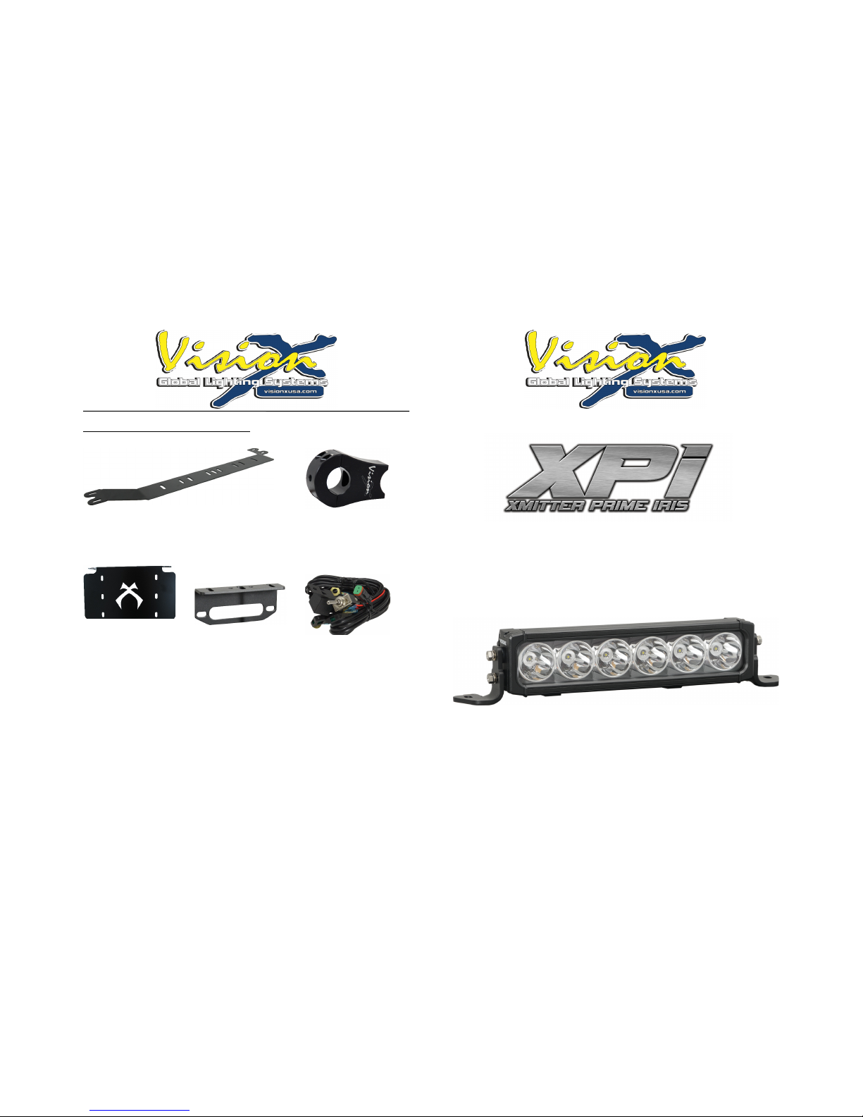
Part # - 4006522
Item # - XIL-B150
Billet Tube Mount
(0.75”-2.0” Diameter Available)
Part # - 4000308
Item # - XIL-LICENSEP
License Plate Mount For Up To
12” LED Light Bars.
Part # - 9892313
Item # - XIL-WINCH6
Winch Mount For Up To 12” LED
Light Bars
Part # - 4006195
Item # - P-HARNESS.XIL
Single Light Harness
www.VISIONXUSA.com
Installation Instructions & User’s Manual

VISION X XPI LIGHT BAR
About the XPI LED Light Bar:
FEATURES
1. IRIS Refl ector Technology For Distance Light Projection
2. Dual Mounting Options; End Cap and Mounting Feet
3. PWM Integrated Dimming Circuitry
XPI LED LIGHT BAR SERIES SPECIFICATIONS
1. Warranty : Extended
2. Amp Draw : 5A - 22.5A (12V)
3. Input Voltage : 9-32V
4. Beam Patterns : Straight (6 LED), Tilted LED’s (9-27 LED)
5. LED Lifespan : 50,000 Hours
PREPARATION
1. We recommend completely reading instructions before installing.
2. Consult your local state regulatory agency regarding the use of LED
lighting.
3. The placement of LED lighting should not restrict airfl ow to the radiator, or
block head lamps, turn signals, or parking lights.
MAINTENANCE
1. All Vision X models have been designed for maintenance free use. In the
case an LED lamp or other part replacement is needed please contact
your authorized service center.
TIP: Vision X recommends the use of liquid thread-locker, or Locktite, to
ensure that every bolt and nut are safely secured.
WARNING: Bolts, Nuts, and Washers are Stainless Steel. DO NOT USE
Pneumatic or Electric Tools to Tighten and Loosen. The Hardware Will
Permanently Lock Together.
Fig. 1
Fig. 2
Fig. 3
Fig. 4
MOUNTING INSTALLATION FOR WINGSINSTALLATION IMAGES
(M1)
(M2)
(M3)
Mounting Wing
(W1)

VISION X XPI LIGHT BAR
MOUNTING INSTALLATION FOR WINGS (END CAPS)
1. Start by placing two (2) rubber grommets [W2] on each side of the LED
bar over the appropriate threaded bolt holes. (See Figure 1)
2. Place the mounting wings [W1] over the rubber grommets and insert the
wing bolts [W3].
3. Use a phillips screwdriver to tighten the wing bolts [W3], starting with the
top bolt fi rst. (See Figure 2)
4. Place the light bar on the location where it will be mounted.
5. Determine where the 5mm bolt [M1] will be placed for each wing, and
mark where the bolt location will be for each side.
6. Drill a hole for the 5mm bolt.
7. Line the light bar wings over the drilled hole and slide the 5mm bolt
through the wing as well as the drilled hole.
8. Slide the washer [M2] on the opposite side of the drilled hole followed by
the nut [M3], and screw until secured.
MOUNTING INSTALLATION FOR FEET
1. Start by setting the light bar in the location that you plan to mount it in.
Mark each end of the light bar and measure the length.
2. Depending on the length of your light bar, you will have a certain
number of mounting feet [F1] included in the packaging. These feet fi t
into grooves on the back of the light bar.
3. Place each mounting feet [F1] (with bolt head pointing into light bar) into
the feet grooves on the back of the light bar.
4. Mark the location of each mounting feet on your vehicle. Drill holes for
each. The feet can slide inside the grooves, letting you fi ne tune the
location.
5. Remove the nut from the feet bolt, and place the light bar onto your
vehicle, line up the bolts with the previously drilled holes.
6. Securely tighten the nut to the mounting feet bolt.
LIGHT ANGLE ADJUSTMENT
1. For the Wing Mount option, simply loosen the bottom wing nut (Fig. 4) on
each end and rotate light bar to desired angle. Fasten when completed.
2. For the Feet Mount option, use the provided allen wrench to loosen both
the Allen bolts on each side the light bar. Once desired angle is achieved,
tighten the bolts.
3. A good reference point is at 20 ft; the top of the beam should be 3” down
from center of light (with the light bar at dead center). Tighten light and
enjoy.
1
2
3
4
7
5
8
6
9
Qty: 1
Qty: 1
Qty: 2
Qty: 1
Qty: 2
Qty: 4
Qty: 2
Qty: 4
LED Light Bar
Pigtail
Hex Head Bolt
(5mm)
Allen Key
(5mm)
Wing Mounts
(Side Mount)
Rubber Grom-
met (Wings)
Mounting Feet
(Bottom Mount)
Nylock Nut
(5mm)
Wing Bolts/
Nuts/Washer
MOUNTING
WIRING PART (M1)
PART (M5)
PART (W1)
PART (W2)
PART (F1)
PART (M3)
PART (W3)
QTY
Varies
MOUNTING FEET BY NUMBER OF LEDS
6LED 9LED 12LED 15LED 18LED 21LED 24LED 27LED
# of
Feet
2 3 4 5 5 6 6 7

VISION X XPI LIGHT BAR
WIRING INSTALLATION
1. If applicable, disconnect/locate the existing connection on your vehicle,
otherwise install a new power source or purchase a wiring harness.
2. Strip both the red and black Pigtail wires, and your power source so that
roughly 1/2” is exposed on each wire.
3. Connect the positive (red [+]) Pigtail wire to the positive wire on your
power source via method of your choice.
4. Repeat the above step for the negative Pigtail wire (black [-]) as well.
5. Now that the wire is connected to the pigtail it is ready to plug into the
LED light for use.
INSTALLATION SUGGESTIONS
1. Vision X recommends professional installation for LED lights.
2. Those less experienced at installing LED lights are recommended to
purchase a wiring harness that connects directly to your vehicle battery.
WARNINGS
As with many other high-tech products, this VISION X LED requires a bit of
attention before you can use it. Please read the accompanying information
carefully fi rst.
1. Don’t stare directly into the light or shine directly into the eyes of another
person as this may cause temporary loss of vision.
2. Never disassemble the products, as all parts must be factory serviced to
insure proper operation.
3. Don’t interchange the parts inside this light with other products.
4. The LED light is to be mounted on the vehicle only in a vertical, bottom
mounting, or in a suspended position.
5. After turning on the light, the body might be hot enough to warrant a burn
risk. Be careful when you touch the body after turning on the light for a
long period of time.
6. Use the supplied wire harness for electrical installation.
7. The LED light must not adversely affect the performance of low beam,
high beam, engine cooling or the driver’s view.
COMPONENTS KEY
Part (P1): Pig Tail With Deutsch Connector
Part (P2): XPI LED Light Bar
TESTING THE LIGHT
1. After all connections have been made start your vehicle and test your
switch to make sure it turns on the light.
2. Make sure the angle of your light is correct, otherwise adjust the light
angle again.
3. Make sure no wire or other components of the harness are exposed to
water spray, excessive heat, or moving parts.
TIP: Vision X recommends checking each bolt and nut, as well as the
connectors after driving your vehicle for an extended period of time to ensure
that each light is securely mounted.
*Harness Available
PIG TAIL WIRING INSTALLATION DIAGRAM
*
PROFESSIONAL INSTALL RECOMMENDED*
-
+
(P1)(P2)
 Loading...