

PERFORMANCE LED
LIGHT DUTY LIGHT
Installation Instructions & User’s Manual
VISIONXLIGHTING.COM
VISION X
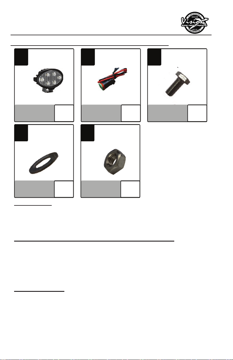
About The VL-Series LED Work Light:
VL-Series
1
4
PART (W1)
FEATURES
1. IP-67 Waterproof Housing
2. Compact Fixture for Universal Applications.
3. 5 Watt CREE LEDs
Light
*actual light may vary
LIGHT
Washer
[M5]
Qty: 1
Qty: 1
2
PART (P1)
5
PART (N1)
Pigtail
*Included only with
certain models
Qty: 1
Nylock Nut
[M5]
Qty: 1
3
PART (B1)
Hex Head Bolt
[M5]
Qty: 1
VL-SERIES LED WORK LIGHT SPECIFICATION
1. Warranty : Extended
2. Input Voltage : 9-32V DC
3. Beam Patterns : 40°
4. LED Lifespan : 50,000 Hours
PREPARATION
1. We recommend completely reading instructions before
installing.
2. Consult your local state regulatory agency regarding the
use of LED lighting.
3. The placement of LED lighting should not restrict airfl ow to
the radiator, or block head lamps, turn signals, or parking
lights.

VL-SERIES LED WORK LIGHT
WARNING: Bolts, Nuts, and Washers are Stainless Steel.
DO NOT USE Pneumatic or Electric Tools to Tighten and
Loosen. The Hardware Will Permanently Lock Together.
WIRING INSTALLATION INSTRUCTION
1. If supplied with the light is a 3” Pigtail, Part (P1), Connect
the positive red wire Part (R1), and negative black wire Part
(B1), into an existing power source.
MOUNTING INSTALLATION INSTRUCTION
1. Determine where the light/lights will be placed.
2. Place mounting bracket with light to desired location. Using
a marker or pick tool, mark the center point of the bolt hole
on the mounting surface.
3. Set the light aside. Drill out a large enough hole to fi t the
[M5] bolt Part (B1).
4. Line up the mounting bracket with the hole you just drilled,
slide the [M5] Bolt (B1) through both.
5. On the other side of mounting surface slide the [M5]
Washer Part (W1) and [M5] Nylock Nut Part (N1) onto the
[M5] Bolt (B1). Tighten Nut & Bolt to desired tightness.
WIRING DIAGRAM (IF APPLICABLE)
COMPONENTS KEY
Part (P1) Pigtail
Part (R1) Power Wire
a. 9-32V DC Positive (+) Input Wire
Part (B1) Ground Wire
a. 9-32V Negative (-) Input Wire
(P1)
(+) Red (R1)
(-) Black (B1)
To Light
TIP: For complete application guide see website
*actual light may vary

MOUNTING DIAGRAM
2.21”/56.2mm
MOUNTING KEY
Part (B1) Bolt
Part (Mounting Bracket)
Part (W1) Washer
Part (N1) Nut
(B1)
(Mounting Bracket)
(W1)
(N1)
LIGHT ANGLE ADJUSTMENTS
1. Use a 13mm socket to loosen the 1 Hex head bolts Part (B2)
on the side of the light.
2. Adjust the light to your desired angle and tighten Bolt (B2).
ADJUSTMENT KEY
Part (B2) Bolt
a. 13mm Hex Head Bolt
(B2)
MAINTENANCE
All Vision X models have been designed for maintenance free use.
In the case that an LED lamp or other part replacement is needed
please contact your authorized service center.
VISIONXLIGHTING.COM
 Loading...