

Page 1
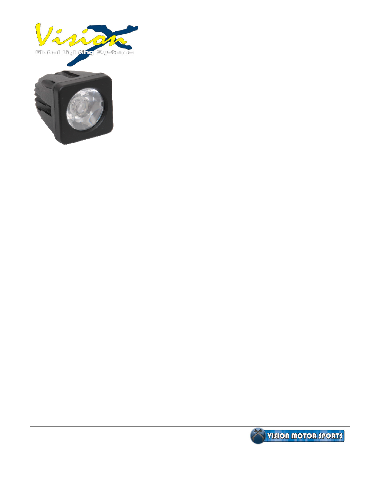
Solstice Solo Series
Installation Instructions
Package Contents;
1. Solstice Solo Series Pod
2. Wiring Pigtail with Deut
3. Universal Stud Mount
4. Horizontal Omn
5. Allen Wrench
Required Tools;
1. ¼” Drill Bit
2. 10mm Socket and Ratchet
3. 10mm Open End Wrench
4. (2) 16 Gau
5. Crimper
6. Wire Stripper
7. Included Allen Wrench
i-Link Connector
ge Barrel Crimps or Soldering Iron, Solder and Heat Shrink
WARNING! – Only use included wiring to wire the
Solstice Solo Series. Even though the plug is the same as
other Vision X wiring, the Solo series has unique circuitry tha
can easily be damaged with wiring other than the included
pigtail.
sche Connector
t
Mounting Instructions;
1. Drill ¼” Hole in desired mounting location.
a. Note – The center of your hole will be the exact ce
nter of the light. Make sure to
measure the location of your hole before drilling.
b. Note – If you are linking multiple pods together using the included Omni-Link conn
carefully read linking in
structions on the bottom of the next page before selecting
placement of mounts.
2. Insert stud mount through the ¼”
hole and tighten the nylock nut with a 10mm socket or wrench
to a maximum torque of 20 ft/lb.
a. Note – DO NOT use air impact tool as they will damage the stainless threads.
3. Remove adjustment set screws if installed on adjustment bracket. Tighten the adjustment
nylock snug against the bracket and aim the light to desired position. After the light is aimed,
tighten the adjustment bolt and nylock to a maximum torque of 20 ft/lb. I
f desired insert and
hand tighten adjustment set screws for use in high vibration scenarios.
Washington Warehouse
901 Algona Blvd N.
Unit F
Algona, Wa 98001
Ph: 888-489-9820
Fx: 253-218-2905
Arizona Warehouse
6501 E. Greenway
Suite 103-542
Scottsdale, Az 85254
Ph: 800-994-4460
Fx: 480-922-5655
www.visionxusa.com
Page 1 of 2
ector,
Page 2
Solstice Solo Series
Installation Instructions
Wiring Instructions;
The Solstice Solo pod draws .75 amps at 12 volts. A relay harness is always
recommended in vehicle applications running more that (5) Solo Pods. Vision X does offer
these for sale; order part # P-HARNESS.SOLSTICE. A maximum of 25 Solo pods per 30 a
mp
12 V DC relay is recommended. If the vehicle does not have a battery one will be needed.
Battery packs are also available for purchase; order Vision X part # XPC-B22 for 3.5 hours of
operation per Solo Pod or XPC-B44 for 7 hours of operation per Solo Pod. Each battery pa
can power a maximum of (2) Solo Pods and will cut the life span of
the battery in half. For
ck
stationary applications, 9-60 V DC is required to operate the pods.
1. Before makin
electronics.
2. Each Deutsche connector pigtail consists
and Black is your negative (-) wire input.
3. The Solo series pigtails come pre stripped with solder terminations. If you are using crimps,
remove solder terminations buy cutting each wire individually and re-strip each wire individually
before crimping.
copper strands.
4. After making your connections, heat shrink ea
and exposure of the copper to the elements.
5. With all of the connections made and insulated with heat shrink you now can plug in and test.
g any connections, unplug all of the Solo pods to avoid damaging the internal
of a red and black wire. Red is your positive (+) input
If soldering, to avoid a “dry” solder make sure solder is well embedded into the
ch individual connection to avoid shorting of wires
Omni-Link System
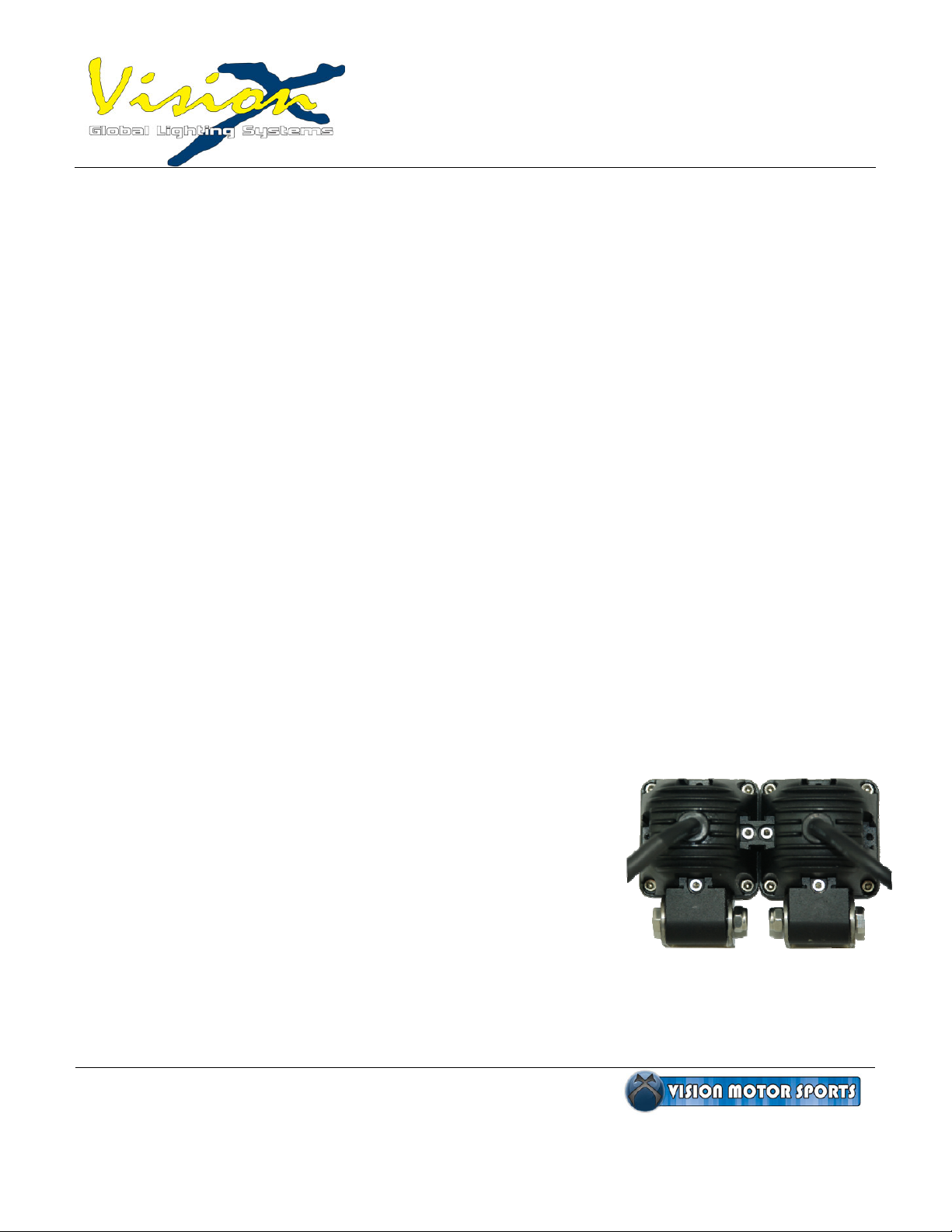
The Solstice Solo Series is equipped the Omni-Link system which allows you to add or
remove multiple types of mounts or link multiple Solo pods together on any of its 4 sides. It is
recommended that (2) mounts are used for every 12 inches of width when connect
ing Solo
Pods. Rows of (2) pods or higher may require an additional upper support mount.
1. To link multiple Solstice Solo Pods together, simply slide the provided Omni-Link into t
Pod’s channels and hand tighten provided Allen bolts with
the included Allen wr
2. he use of a thread locking agent is recommended for high
T
ibration situations.
v
ench.
For more mounting application
isit www.VISIONXUSA.com
V
Washington Warehouse
901 Algona Blvd N.
Unit F
Algona, Wa 98001
Ph: 888-489-9820
Fx: 253-218-2905
s including helmet and handlebar mounts;
Arizona Warehouse
6501 E. Greenway
Suite 103-542
Scottsdale, Az 85254
Ph: 800-994-4460
Fx: 480-922-5655
www.visionxusa.com
Page 2 of 2
he Solo
 Loading...