

Vision X 8.7"" CG2 LED Light Cannon Installation Instructions & User Manual
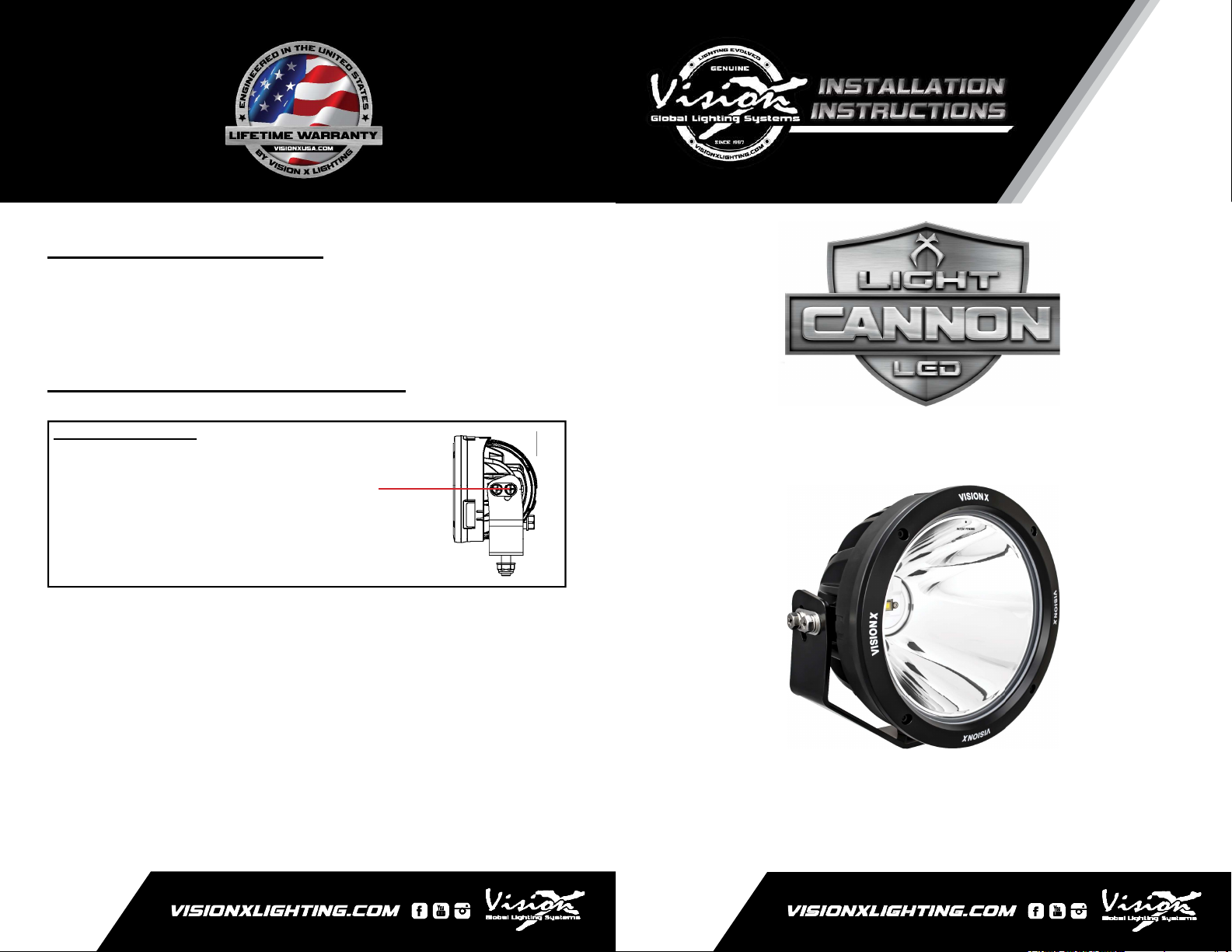
LIGHT ANGLE ADJUSTMENTS
1. Use a 13mm socket to loosen the 2 Hex head bolts Part
(B2) on each side of the light.
2. Adjust the light to your desired angle and tighten Bolts (B2).
LIGHT ANGLE ADJUSTMENT DIAGRAM:
ADJUSTMENT KEY
Part (B2) Bolt
a. 13mm Hex Head Bolt
8.7” CG2 LED LIGHT CANNON
Installation Instructions & User’s Manual
(B2)
VISION X
About The 8.7” CG2 LED Light Cannon:
8.7” CG2 LED LIGHT CANNON
1
4
PART (W1)
FEATURES
1. Lightweight hybrid housing.
2. Integrated electronic thermal management (ETM).
3. Single 100 watt LEDs produce 3,500’ of usable light.
8.7” CG2 LED LIGHT CANNON SPECIFICATION
1. Warranty : Extended
2. Amp Draw : 8.3A @ 12V DC
3. Input Voltage : 9-32V DC
4. Beam Patterns : 10°, Snap-On Filters Available
5. LED Lifespan : 50,000 Hours
PREPARATION
1. We recommend completely reading instructions before
2. Consult your local state regulatory agency regarding the
3. The placement of LED lighting should not restrict airfl ow to
CG2
Cannon
LIGHT
Washer
installing.
use of LED lighting.
the radiator, or block head lamps, turn signals, or parking
lights.
Qty: 1
[M12]
Qty: 1
2
PART (P1)
5
PART (N1)
Pigtail
Qty: 1
Nylock Nut
[M12]
Qty: 1
Hex Head Bolt
3
PART (B1)
[M12]
Qty: 1
WARNING: Bolts, Nuts, and Washers are Stainless Steel.
DO NOT USE Pneumatic or Electric Tools to Tighten and
Loosen. The Hardware Will Permanently Lock Together.
WIRING INSTALLATION INSTRUCTION
1. Supplied with the Light Cannon is a 3” Pigtail.
2. Connect the positive (red) wire and negative (black) wire
into an existing power source.
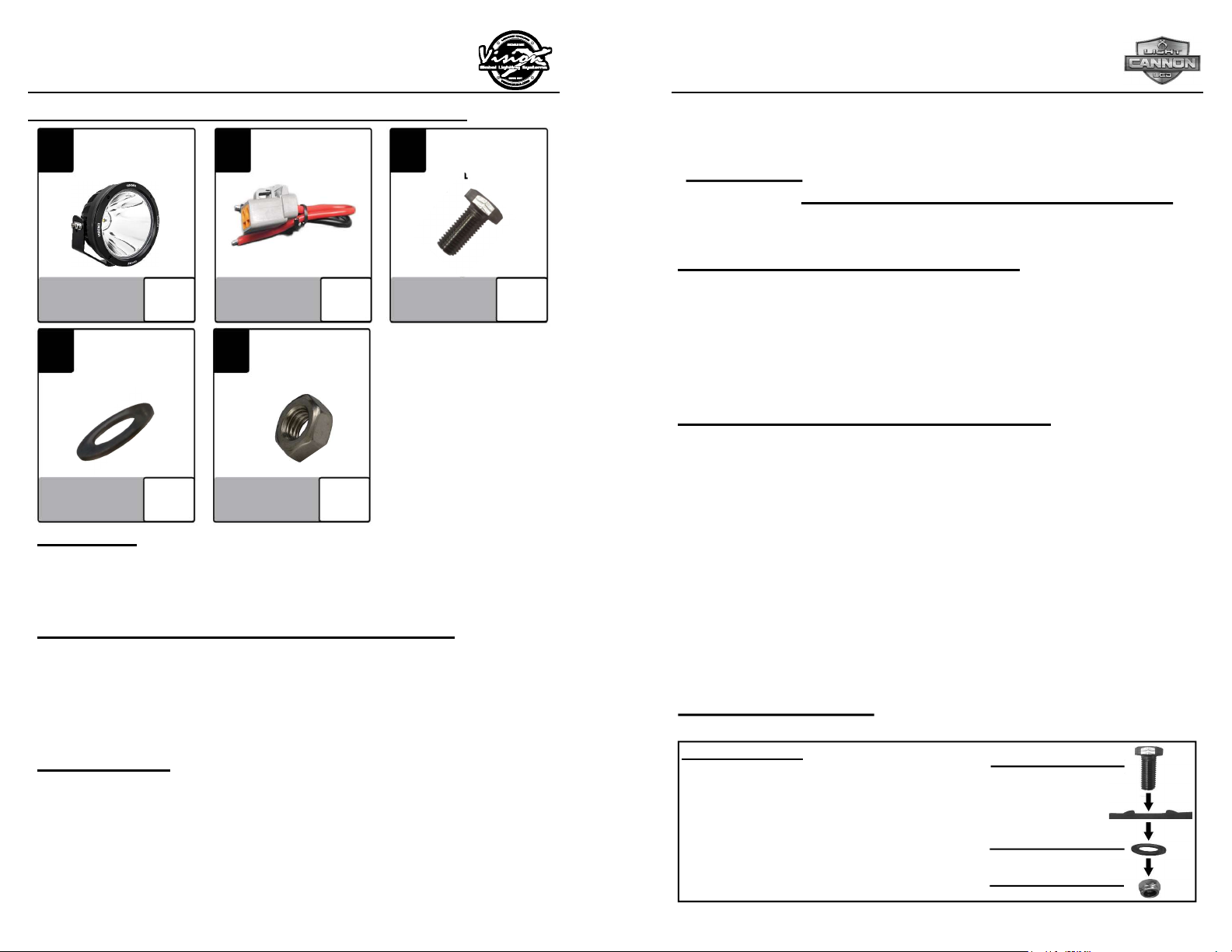
MOUNTING INSTALLATION INSTRUCTION
1. Determine where the light/lights will be placed.
2. Place mounting bracket with light to desired location. Using
a marker or pick tool, mark the center point of the bolt hole
on the mounting surface.
3. Set the light aside. Drill out a large enough hole to fi t the
[M12] bolt Part (B1).
4. Line up the mounting bracket with the hole you just drilled,
slide the [M12] Bolt (B1) through both.
5. On the other side of mounting surface slide the [M10]
Washer Part (W1) and [M12] Nylock Nut Part (N1) onto the
[M12] Bolt (B1). Tighten Nut & Bolt to desired tightness.
MOUNTING DIAGRAM
MOUNTING KEY
Part (B1) Bolt
Part (Mounting Bracket)
Part (W1) Washer
Part (N1) Nut
(B1)
(Mounting Bracket)
(W1)
(N1)
 Loading...