

Vision UPS Systems Spirit G XL 2KVAS, Spirit G XL 1.5KVAH, Spirit G XL 1.5KVAS, Spirit G XL 2KVAH, Spirit G XL 3KVAH User Manual
...
User manual
Spirit G XL
1-3 KVA – PF0.9
U
ninterruptible Power Supply

SPIRIT G XL 1-3 KVA - PF0.9 - UPS www.visionups.com
2
All rights reserved.
The information in this manual is subject to change without notice.
Thank you for purchasing this series UPS. It is secure and reliable and requires only low maintenance.
Please read this manual carefully and entirely. It contains instructions about safety, installation and operation. These will help
you to reach maximum life time of your UPS. This manual explains the inner working principle and the corresponding
protective functions. Furthermore, it contains information regarding the use of the equipment.
Carefully follow the given instructions and warning messages in this manual or on the device itself. Only use the equipment
once you had fully read the safety and operation instructions.
Remark: Our products might differ slightly from the data in this manual due to continual improvements. If needed contact a
local representative to get further information.

SPIRIT G XL 1-3 KVA - PF0.9 - UPS www.visionups.com
3
TABLE OF CONTENTS
1. Introduction……………….…..…………………………….….…………………………………………..….……………………………. 5
2. Safety Warnings...….……...………………………........................................................................................... 6
3. Installation …………………………………………….…………………………............................................................... 7
3.1. Unpacking and Inspecting the Equipment..………………...…….................................................. 7
3.2. Checking the accessories..….……..….……….………………………..................................................... 7
3.3. Rack mount Installation..………………………………………………..………….......................................... 8
3.4. Rack mount Wiring Installation……...…….……………………………................................................. 9
3.5. Connecting the Battery Packs (EBPs)…………….……….………….................................................. 11
3.6. Rack mount converted to Tower Installation…………………………………….…............................... 12
3.7. UPS Initial Start-up……………….……………….…………………………………………………………………………. 14
4. Display Monitor, Operation and Control………………………..….…...…....................................................... 15
4.1. Control functions…………………………………................................................................................ 15
4.2. Display Functions…….……………………………………………………...................................................... 17
4.3. Parameters Inquiring………….………..…….…………………………….................................................. 18
4.4. Parameter Settings………………..………………………..................................................................... 19
4.5. Start up and Turn off the UPS..……………………........................................................................ 23
5. Communication….……………………….….…………………............................................................................... 25
5.1. Communication Options and Control Terminals…................................................................. 25
5.2. RS232 and USB Communication Ports……….……..……………………………………………………………… 26
5.3. Connectivity Cards..…………………………………………………………………………….………………………...... 26
5.4. Emergency Power Off (EPO)…………….…………………………………………………............................... 27
5.5. Load Segments.......……………………………………………………………………………….............................. 28
5.6. UPSilon2000 Power Management Software…………………………………………………………………….. 28
6. Maintenance.……………………………………………………..……....….................................................................. 29
6.1. Maintenance of UPS and Batteries.………………….................................................................... 29
6.2. Storing the UPS and Batteries…..……………............................................................................. 29
6.3. Replacing the Batteries…………………………………...................................................................... 29
6.4. Replacing the UPS (R/T) and Battery Packs (EBPs)……........................................................... 30
6.5. Testing New Batteries…..…………......…………………................................................................... 30
6.6. Recycling the Used Batteries and the UPS………………………………………………………………………… 31
7. Specifications…..…………………………………………………..……....…................................................................ 31
7.1. Model Specifications..……………….…………………….................................................................... 31
7.2. Rear Covers……………………………..………………........................................................................... 35
8. Troubleshooting………...………………………………………..……....…................................................................ 36
CONTENT LIST OF TABLES
Table 1 Indicator descriptions…………………………………………………………………………………………………….. 15
Table 2 Button functions..…………………………………………………............................................................ 15
Table 3 Operating status corresponding to indications………..…………………………………………………….. 16
Table 4 LCD Display ……………………………………………………………..…………………………………………………….. 17
Table 5 Parameters inquiring..……………………………..…………………………………………………………………….. 18
Table 6 Parameters settings………………………………..……………….…………………………………………………….. 19
Table 7 Operation modes…………………………………….………………..…….…………………………………………….. 22
Table 8 Battery number configuration…………….……………………..………………………………………………….. 24
Table 9 Pin assignment of RS232 communication port….……………………………………………………………. 26
Table 10 Communication options…………………………………….......…………………………………………………….. 31
Table 11 Extended battery model…………………………………………………………………….………………………….. 31
SPIRIT G XL 1-3 KVA - PF0.9 - UPS www.visionups.com
4
Table 12 UPS models……..…………………………………………………………………………………………………………….. 31
Table 13 Weights and dimensions………..………………………………………………………………………………………. 32
Table 14 Electrical input A. ………………………………………………………………………………………………………….. 32
Table 15 Electrical input B. ………………………………………………………………………………………………………….. 32
Table 16 Electrical input connections…….…………………………………………………………………………………….. 32
Table 17 Electrical output…………………………………………………………………………………………………………….. 32
Table 18 Electrical output connections…………………………………………………………………………………………. 33
Table 19 Environment and safety………………………………………………………………………………………………….. 33
Table 20 Internal charger…….……………………………………………………………………………………………………….. 34
Table 21 Battery runtimes at 100% load….……………………………………………………………………………………. 34
Table 22 Battery...……..…………………………………………………………………………………………………………………. 34
Table 23 Troubleshooting….…………………………………………………………………………………………………………. 36
Table 24 Warnings messages and fault codes….…………………............................................................. 37
-----------------------------------------------
Class B EMC Statements – FCC Part 15
This equipment has been tested and found to comply with the limits for a Class B digital device, pursuant to part 15 of the
FCC Rules. These limits are designed to provide reasonable protection against harmful interference in a residential installation.
This equipment generates, uses and can radiate radio frequency energy and, if not installed and used in accordance with the
instructions, may cause harmful interference to radio communications. However, there is no guarantee that interference to
radio or television reception, which can be determined by turning the equipment off and on, the user is encouraged to try to
correct the interference by one or more of the following measures:
Reorient or relocate the receiving antenna.
Increase the separation between the equipment and the receiver.
Connect the equipment into an outlet on a circuit different from that to which the receiver is connected.
Consult the dealer or an experienced radio/TV technician for help.
Special Symbols
The following are examples of symbols used on the UPS or accessories to alert you to important information:
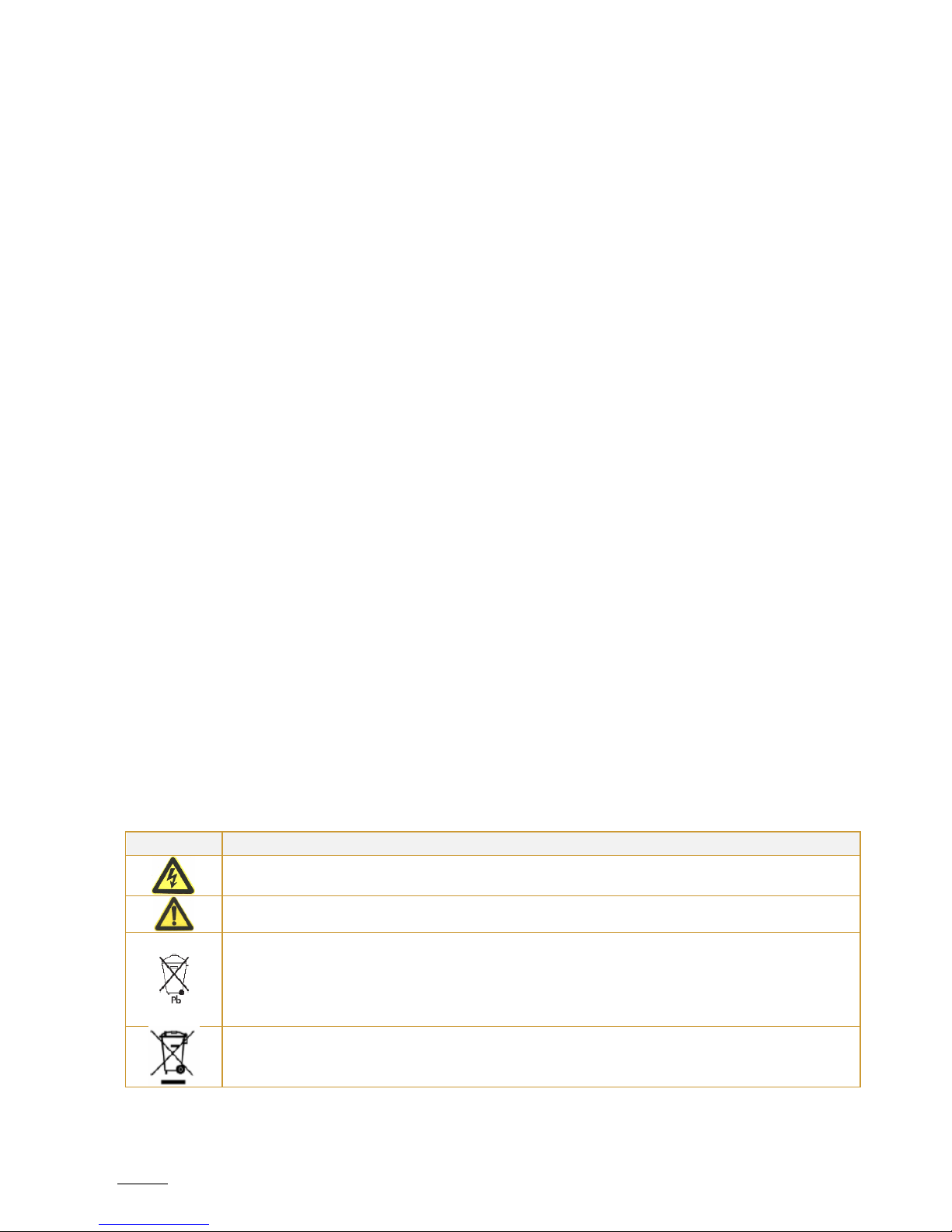
Symbol
Indication
Risk of electric shock – Observe the warning associated with the risk of electric shock symbol
Caution – need your attention
Indicates that you should not discard the UPS or the UPS batteries in the trash. This product contains
sealed, lead-acid batteries and must be disposed of properly. For more information, contact your
local recycling/reuse or hazardous waste center.
Indicates that you should not discard waste electrical or electronic equipment (WEEE) in the trash.
For proper disposal, contact your local recycling/reuse or hazardous waste center.

SPIRIT G XL 1-3 KVA - PF0.9 - UPS www.visionups.com
5
1. INTRODUCTION
This UPS protects your sensitive electronic equipment from most common power problems, including power failures, power
sags, power surges, brownouts, line noise, high voltage spikes, frequency variations, switching transients and harmonic
distortion.
Power outages might occur unexpectedly and power quality can be erratic. These power problems have potential to corrupt
critical data, destroy unsaved work sessions and damage hardware – causing hours of lost productivity and expensive repairs.
With the UPS, you can safely eliminate the effects of power disturbances and guard the integrity of your equipment. Providing
outstanding performance and reliability, the UPS’s unique benefits include:
True online double-conversion technology with high power density, utility frequency independence and generator
compatibility. Output power factor up to 0.9.
Three segment charging mode to increase battery service life, optimize recharge time.
Selectable High Efficiency mode of operation.
Cold start function to start-up the UPS without utility.
Standard communication options: one RS232 communication port, one USB communication port and relay output
contacts or SNMP card.
Power shedding function may turn off uncritical load in battery backup to make longer backup time for critical load.
Extended runtime with up to four Extended Battery Modules (EBPs) per UPS.
Emergency shutdown control through the Remote Emergency Power-off (EPO) port.
The content displayed on the interface is rich. The capacity of the loads and the battery can be seen directly and the
FLASH pictures and fan rotating icon can be displayed while charging. Enhance, it is easy to know its operation status.
When UPS fails, it can show the fault code; therefore, the UPS can be repaired as soon as possible by inquiring fault
code table.
NOTICE: In the manual, RT is short for Rack-Tower conversion.
Rack/Tower convertible LCD design. No matter what angle required, only pressing the key slightly to reach your
perspective needs.
For RT model, it is equipped with hot swappable battery feature needed for 19“rack solution.
RT models in a space-optimizing 2U size fits any standard 19“rack.
Fig. 2 – The Rackmount EBP front view
Fig. 1 – The Rackmount UPS front view
SPIRIT G XL 1-3 KVA - PF0.9 - UPS www.visionups.com
6
2. SAFETY WARNINGS
This chapter contains important instructions that you should follow during installation and maintenance of the UPS and
batteries. Please read all instructions before operating the equipment and save this manual for future reference.
Following the safety instructions:
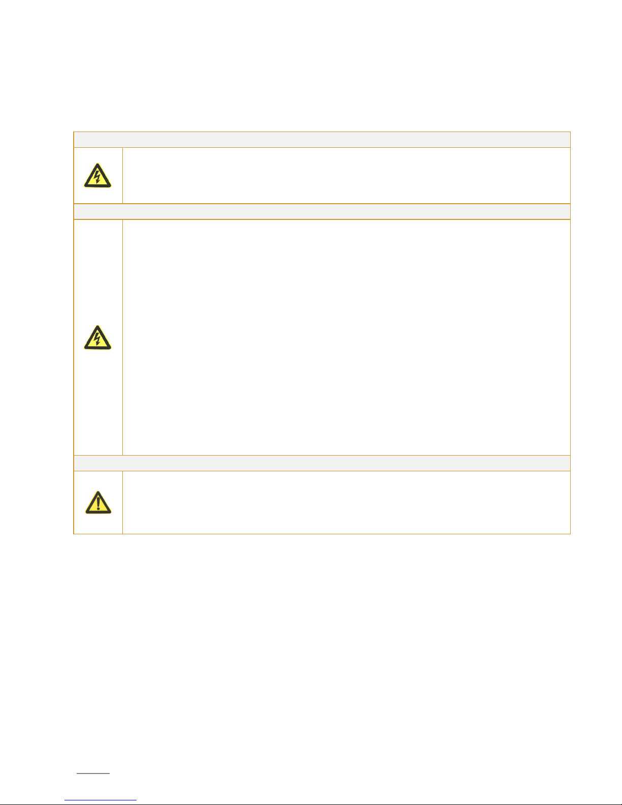
DANGER
The UPS contains lethal voltages. All repairs and service should be performed by authorized service
personnel only. Please follow the local safety regulations and corresponding laws during installation,
operation and maintenance; because otherwise it may result in injury and/or equipment damage. The
safety instructions in this manual serve in addition to the local valid safety regulations.
There are no user serviceable parts inside the UPS.
WARNING
The UPS contains its own energy source (batteries). The UPS output may carry live voltage even when
the UPS is not connected to an AC supply.
To reduce the risk of fire or electric shock, install the UPS in a temperature and humidity controlled,
indoor environment, free of water, corrosive gases, conductive contaminants or strong dust formation.
Ambient temperature must not exceed 40°C. But to preserve batteries lifetime, we advise you to an
operating temperature of 20°C to 25°C.
Do not place any liquids on the UPS cabinet in order to not trigger electrical discharges nor other
dangers.
To reduce the risk of fire, connect only to a circuit provided with branch circuit overcurrent protection
in accordance with the National Electrical Code (NEC), ANSI/NFPA 70.
Output overcurrent protection and disconnect switch must be provided by others.
To comply with international standards and wiring regulations, the sum of the leakage current of the
UPS and the total equipment connected to the output of the UPS must not have an earth leakage
current greater than 3.5 milliamperes.
If installing optional rack mount EBP(s), install the EBP(S) directly below the UPS so that all wiring
between the cabinets is installed behind the front covers and is inaccessible to users. The maximum
number of EBP(s) per UPS is four.
If the UPS requires any type of transportation, verify that the UPS is unplugged and turned off and then
disconnect the UPS internal battery connector.
CAUTION
Batteries can present a risk of electrical shock or burn from high short-circuit current. Observe proper
precautions. Servicing should be performed by qualified service personnel knowledgeable of batteries
and required precautions. Keep unauthorized personnel away from batteries.
Proper disposal of batteries is required. Refer to your local codes for disposal requirements.
Never dispose of batteries in a fire. Batteries may explode when exposed to flame.

SPIRIT G XL 1-3 KVA - PF0.9 - UPS www.visionups.com
7
3. INSTALLATION
This section explains:
- Equipment unpacking and inspection;
- Checking the accessory kit;
- Cabinet installation;
- Wiring installation;
- Initial start-up.
3.1. Unpacking and inspecting the Equipment
3.1.1. Unpack the UPS and check it for any transport damage. Do not put the unit into operation in case of damage
or of missing parts and keep all packing material for the forwarder and/or dealer. Inform the forwarder and
the dealer.
3.1.2. Check if the delivered equipment is indeed the one you wanted to buy. You can do that by checking the
model number on the unit rear side.
3.1.3. CAUTION:
Unpacking the UPS in a low-temperature environment may cause condensation to occur in and on the
cabinet. Do not install the cabinet until the inside and outside of the cabinet are absolutely dry (hazard
of electric shock).
The UPS is heavy (see page 32 «Weights and dimensions»). Be careful to unpack and move the
equipment.
3.1.4. Place the UPS in a clean and solid location. Avoid places with vibrations, dust, high humidity, flammable gas,
liquids and corrosion.
3.1.5. The ambient temperature must not exceed 40°C maximum. To preserve batteries lifetime, we advise an
operating temperature of 20°C to 25°C.
3.1.6. The UPS must be installed in a location with sufficient ventilation.
3.2. Checking the accessories
3.2.1. The accessory of inverter contains:
- UPS user’s manual;
- Software-Suite-CD;
- USB cable;
- Power cord (input and output);
- RS232 cable;
- In case of an ordered optional Extended Battery Module (EBP): manual of EBP.
Note: Discard the EBP user manual if you are installing the EBP with a new UPS at the same time. Use the
UPS user manual to install both – UPS and EBP.
3.2.2. The accessory of rail kit (options) – check if following rail kit items are included for each inverter:
a) Left rail assembly: left rail, rear rail, 3 x pan-head screws M5_8.
b) Right rail assembly: right rail, rear rail, 3 x pan-head screws M5_8.
c) Rail hardware kit: 8 x butterfly nuts M5, 2 x rear stop brackets, 8 x umbrella nuts M5.
d) Mounting bracket kit: 2 x mounting brackets, 8 x flat-head screws M4_8.
3.2.3. Tools required – to assemble the components, you need the following tools: cross-shaped screwdriver,
wrench or socket of 6mm.
SPIRIT G XL 1-3 KVA - PF0.9 - UPS www.visionups.com
8
3.3. Rack mount Installation
3.3.1. Rack Installation:
The rack mount cabinet is delivered with all accessories, which are required for installation on a standard
EIA or JIS seismic rack mount configuration with square and round mounting holes.
In 19”-racks, the rail assemblies can be adjusted in depth from front to rear around 50cm until approximately
80cm.
3.3.2. PRECAUTIONS during the Rack-Mount:
The cabinet is heavy. Removing it from its carton requires a minimum of two people.
If installing optional EBP(s), make sure to install the EBP(s) directly below the UPS in order that all wiring
between inverter and external batteries is installed behind the front cover and thus inaccessible to
users.
NOTE: mounting rails are required for each individual cabinet.
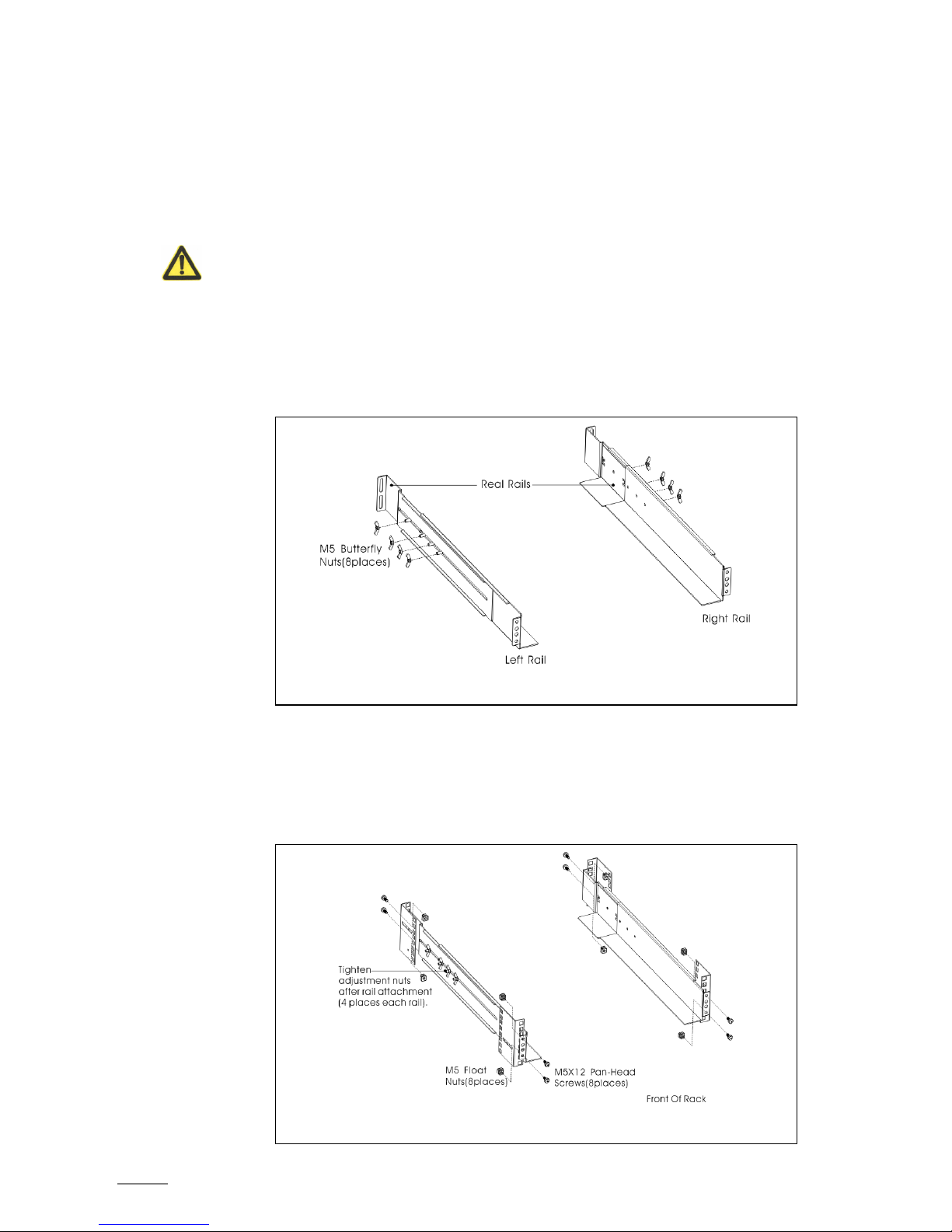
3.3.3. Installation of the rail kit:
① Assemble the left and right rails to the rear rails as shown in figure 3 below. Do not over tighten the
screws. Adjust each rail size for the depth of your rack.
② Select the proper size in the rack for positioning the UPS (see fig. 4). The rail occupies four positions
on the front and rear of the rack.
③ Tighten four M5 umbrella nuts in the side of rail assembly (see fig. 3).
④ Fix one rail assembly to the front of the rack with one M5x12 pan-head screw and one M5 cage nut.
Use two M5 cage nuts and two M5x12 pan-head screws to fix the rail assembly to the rear of the
rack.
Fig. 3 – Assembly of the rails
Fig. 4 – Fixing the rails
SPIRIT G XL 1-3 KVA - PF0.9 - UPS www.visionups.com
9
⑤ Repeat the steps ③ and ④ to assemble the other rails.
⑥ Tighten the four butterfly nuts in the middle of each rail assembly.
⑦ If installing optional modules, then repeat step ① through step ⑥ for each rail kit.
⑧ Place the UPS on a flat, stable surface with the front of the device facing to you.
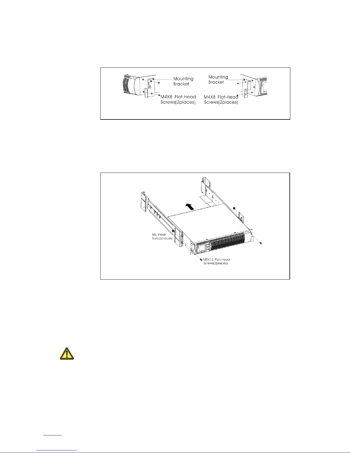
⑨ Align the mounting brackets with the screw holes on each side of the UPS and fix it all with the
supplied M4x8 flat-head screws (see fig. 5).
⑩ If installing optional modules, repeat step ⑧ and ⑨ for each module.
⑪ Slide the UPS and any other optional module into the rack.
⑫ Secure the front of the UPS to the rack by using one M5x12 pan-head screws and one M5 cage nuts
on each side (see fig. 6). Install the bottom screw on each side through the bottom hole of mounting
bracket and the bottom hole of the rail. Repeat that for any optional module.
⑬ Continue to the following section «Rackmount Wiring Installation».
3.4. Rack mount Wiring Installation
This section explains:
- Installation of the UPS, including connecting the UPS internal batteries;
- Connection of all optional EBP(s).
3.4.1. Installation of the UPS
NOTE: Do not make unauthorized changes to the UPS; otherwise, damage may occur to your equipment
and void your warranty.
NOTE: Do not connect the UPS power cord to utility before the installation is completed.
Fig. 5 – Installing the mounting brackets
Fig. 6 – Securing the front of the module
SPIRIT G XL 1-3 KVA - PF0.9 - UPS www.visionups.com
10
Follow these steps to install the UPS:
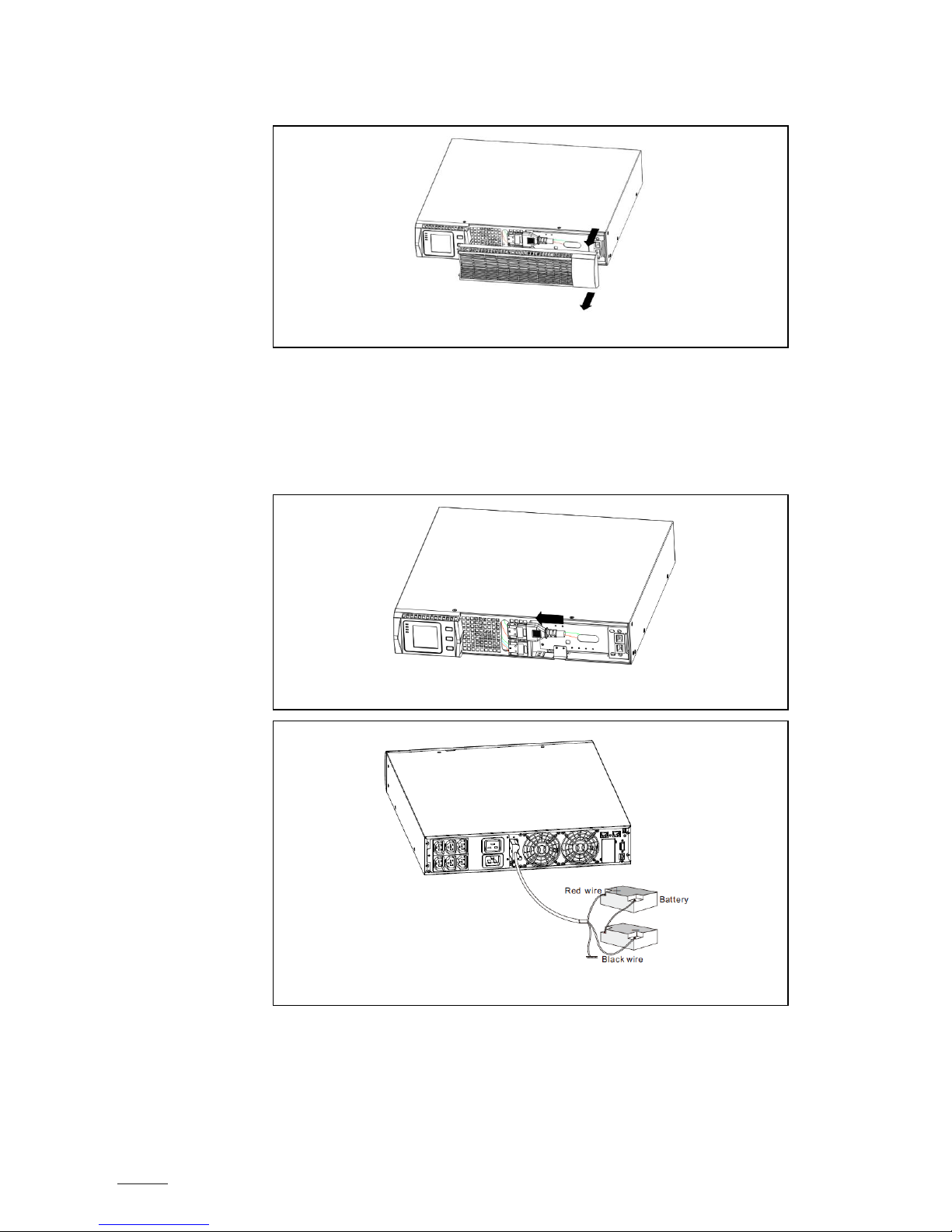
① Remove the front cover of each UPS, hold and extract the right cover part (without LCD) from the
panel (see fig. 7).
② Connect the internal battery connector red to red (see fig. 8). Press the connector firmly in to ensure
a proper connection.
Remark: Note that the above steps ① and ② are only concerning the replacement of batteries or
the addition of internal batteries. If the UPS is delivered with installed internal batteries, then the
plug is already connected.
CAUTION: A small electric arc may occur when connecting the internal batteries. This is normal and
will not harm personnel. Connect the cables quickly and firmly.
③ If you are installing EBPs, then read the following section «Connecting the Battery Packs (EBPs)»
before continuing with the UPS installation.
④ Replace the UPS front cover: if EBPs are installed, verify if the EBP cable has been well routed
through the knockout-opening in the knockout metal sheet before replacing the cover. Afterwards,
mount back the cover.
Fig. 7 – Extract the UPS front cover
Fig. 8 – Connection of internal batteries of the UPS
Fig. 9 – Connection of long backup external battery
SPIRIT G XL 1-3 KVA - PF0.9 - UPS www.visionups.com
11
⑤ If you are installing a power management software, connect your computer to one of the
communication ports or optional connectivity card. For the communication ports, use an
appropriate cable.
⑥ If your rack has conductors for grounding or for bonding of ungrounded metal parts, then connect
the ground cable (not supplied) to the ground bonding screw. See «Rear Covers» for the location
of the ground bonding screw for each model.
⑦ If an emergency power-off (disconnect) switch is required by local codes, see «Remote Emergency
Power-Off (REPO)» to install the REPO switch before powering on the UPS.
⑧ Continue under section «UPS Initial Start-up».
3.5. Connecting the Battery Packs (EBPs)
Follow these steps to install the battery packs (EBPs) for a UPS:
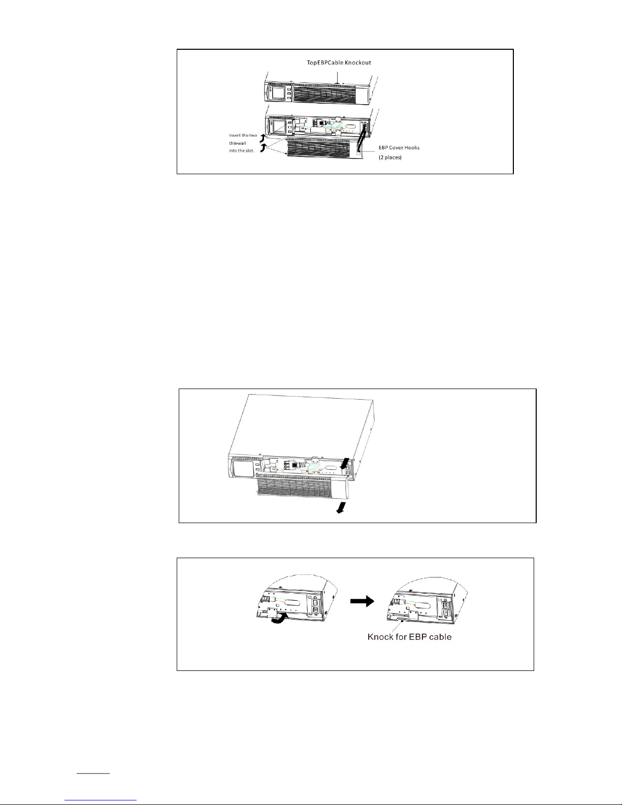
① Remove the front cover of each EBP and of the UPS (see fig. 11) as explained in section «Installation
of the UPS».
② Remove the small cable knockout metal sheet on the lower border of the UPS front cover, which is
intended for the EBP cable passages (see fig. 12).
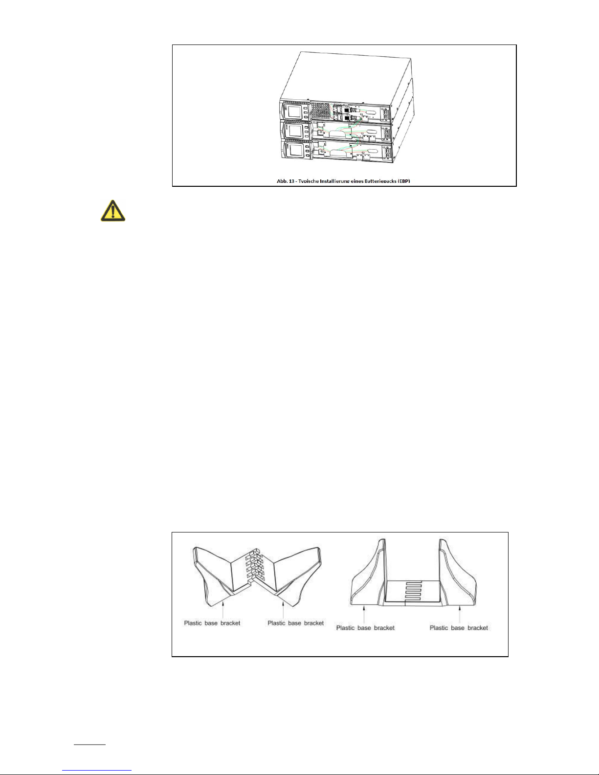
③ For the undermost EBP – as well as for a single battery pack -, remove also the small knockout metal
sheet on the upper border of the front cover. And if you are installing more than a single battery
pack (EBP), then remove for each additional pack this knockout metal sheet on the upper and lower
border of the front cover (see fig. 13 for the location of the knockouts for the EBP cable passages
coming from above). Except the lower metal sheet of the last pack does not have to be removed.
Fig. 10
Fig. 11 – Removing the EBP front cover
Fig. 12 – Removing the small knockout metal sheet for passing the cables
SPIRIT G XL 1-3 KVA - PF0.9 - UPS www.visionups.com
12
CAUTION:
A small electric arc may occur when connecting the internal batteries (EBP) to the UPS. This is normal and
will not harm personnel. Connect the cables quickly and firmly.
④ Plug the EBP cable(s) into the battery connector(s) (see fig. 13). Up to four EPBs may be connected
to the UPS. Connect black to black. Press the connector tightly together to ensure a proper
connection.
⑤ To connect a second battery pack (EBP), unclip the EBP connector on the first EBP and pull gently
to extend the wiring to the EBP connector on the second EBP. Repeat for additional EBPs.
Verify that the EBP connections are tight and the adequate bend radius and strain relief exist for
each cable.
⑥ Replace the EBP front cover after verifying that the EBP cables are correctly routed through the EBP
cover knockouts and that the cover clips properly into the cover hooks on the left module side.
Repeat that for each additional EBP. Refer to «UPS Installation» for the installation of the front
cover.
⑦ Ensure that all wires connected between the UPS and the EBP(s) are installed behind the front cover
and thus not accessible to users.
3.6. Rack mount converted to Tower Installation
3.6.1. Rack mount converted to Tower by plastic base installation
For simple upright placing of the device, mount the plastic holders as follows:
① Nest the two plastic brackets as on fig. 14.
② Flatten the nested part.
Fig. 14 – Assembly of the plastic holder
 Loading...