

Page 1

Super Night Vision
IR Vandalproof Dome Camera
INSTRUCTION MANUAL
Power Option
· 12VDC / 24VAC
080318-1
Please read this manual carefully before installation and operation of the product.
Page 2
Dear Customers!
By selecting this product, you have decided to use a professional device that
guarantees highest quality and reliability. We would like to thank you very much for
your confidence and kindly ask you to read the following instructions carefully
before Installation and operation in order to take full advantage of all quality
features regarding this product.
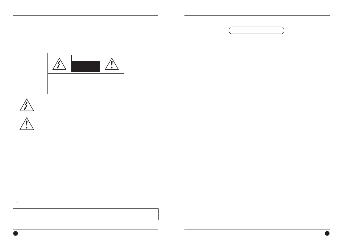
CAUTION
RISK OF ELECTRIC
SHOCK
DO NOT OPEN
TO REDUCE THE RISK OF ELECTRIC SHOCK,
DO NOT REMOVE THE COVER (OR BACK).
REFER SERVICING TO QUALIFIED PERSONNEL.
The lighting flash with an arrowhead symbol, within an equilateral
triangle is intended to alert the user to the presence of uninsulated
dangerous voltage within the product’s enclosure that may be of
sufficient magnitude to constitute a risk of electric shock to persons.
The exclamation point within an equilateral triangle is intended to
alert
the user to the presence of important operating and maintenance
(servicing) instructions in the literature accompanying the appliance.
CAUTION
NO USER SERVICEABLE PARTS INSIDE.
INFORMATION
This equipment has been tested and found to comply with limits for a Class A digital
device, pursuant to part 15 of the FCC Rules. These limits are designed to provide
reasonable protection against harmful interference when the equipment is operated
in a commercial environment. This equipment generates, uses, and can radiate radio
frequency energy and, if not installed and used in accordance with the instruction
manual, may cause harmful interference to radio communications. Operation of this
equipment in a residential area is likely to cause harmful interference in which case
the user will be required to correct the interference at his own expense.
WARNING
Changes or modifications not expressly approved by the manufacturer could void
the user’s authority to operate the equipment.
CAUTION – To prevent electric shock and risk of the fire hazards
Do NOT use power source other than that specified.
Do NOT expose this appliance to rain or moisture.
This installation should be made by a qualified service person and should conform to
all local codes.
Table of contents
1. Precautions ------------------------------------------------------- 4
2. Limitation of liability --------------------------------------------- 5
3. Disclaimer of warranty ----------------------------------------- 5
4. Package ----------------------------------------------------------- 6
5. Installation ----------------------------------------------------- 7~9
6. Features ----------------------------------------------------- 10~12
7. Trouble shooting guide --------------------------------------- 13
8. Dimension ------------------------------------------------------- 14
9. Specification ---------------------------------------------------- 15
2 3
Page 3

1. Precautions 2. Limitation of liability
· Please read the manual carefully before the installation in order to make use the
camera to be set up correctly and to have the best picture quality.
· Please keep the manual in good condition for your future reference and service
application.
· Installation and services should only be carried out by an authorized personnel
according to local safety regulations.
· If any liquid or solid matter gets into the housing, immediately disconnect the
camera
from power supply and have it checked by your authorized dealer before reusing.
·
Avoid installing the camera at extremely hot or cold places.
If you are not a certified person, never try to dismantle the camera. To avoid
·
electric
shock, never remove the screws or covers. There are no parts inside that need
maintenance by the user. All maintenance should be carried by qualified personnel.
·
Avoid installing the camera at a place of high humidity.
Avoid installing the camera at the place exposed to gas or oil.
·
·
Keep the top glass of the lens always clean in order to obtain the best picture
quality
all the time. Be careful not to be stained by fingerprint.
·
Don't face the camera directly toward sunlight or sunlight reflecting area.
CCD may go defective at this condition.
· Please give a special attention to keep the unit from dangerous drop or external
shock
during the process of transportation or handling.
·
Never try to touch the camera in wet hand. It may cause an electric shock.
· Do not put objects inside the unit. Make sure that no metal objects or flammable
substances get into the camera. It could cause fire, short-circuits or damages.
Do not expose the camera to radioactivity. It causes a serious damage on the
·
CCD.
·
Install away from electric or magnetic fields.
☞ Note for 12VDC/24VAC Power type camera user
Make sure to use a regulated 12VDC or 24VAC power source.
Check the power with the power tester to make sure if the power supply gives an
exact 12VDC or 24VAC regulation. Even sometimes UL marked power supply unit
generates unstable power causing the camera to burn in many cases.
This publication is provided “AS IS” without warranty of any kind, either express
or implied, including but not limited to, the implied warranties of merchantability,
fitness for any particular purpose, or noninfringement of the third party's right. This
publication could include technical inaccuracies or typographical errors. Changes are
added to the information herein, at any time, for the improvements of this
publication and/or the corresponding product(s).
3. Disclaimer of warranty
In no event shall seller be liable to any party or any person, except for replacement
or reasonable maintenance of the product, for the cases, including but not limited to
below :
(1) Any damage and loss, including without limitation, direct or indirect, special,
consequential or exemplary, arising out of or relating to the product;
(2) Personal injury or any damage caused by inappropriate use or negligent
operation
of the user;
(3) unauthorized disassemble, repair or modification of the product by the user;
(4) Inconvenience or any loss arising when images are not displayed, due to any
reason
or cause including any failure or problem of the product;
(5) Any problem, consequential inconvenience, or loss or damage, arising out of the
system combined by the devices of third party.
(6) Any claim or action for damages, brought by any person or organization being
photogenic subject, due to violation of privacy with the result of that surveillance camera's picture, including saved data, for some reason, becomes public or is
used
for the purpose other than surveillance.
4 5
Page 4
4. Package 5. Installation
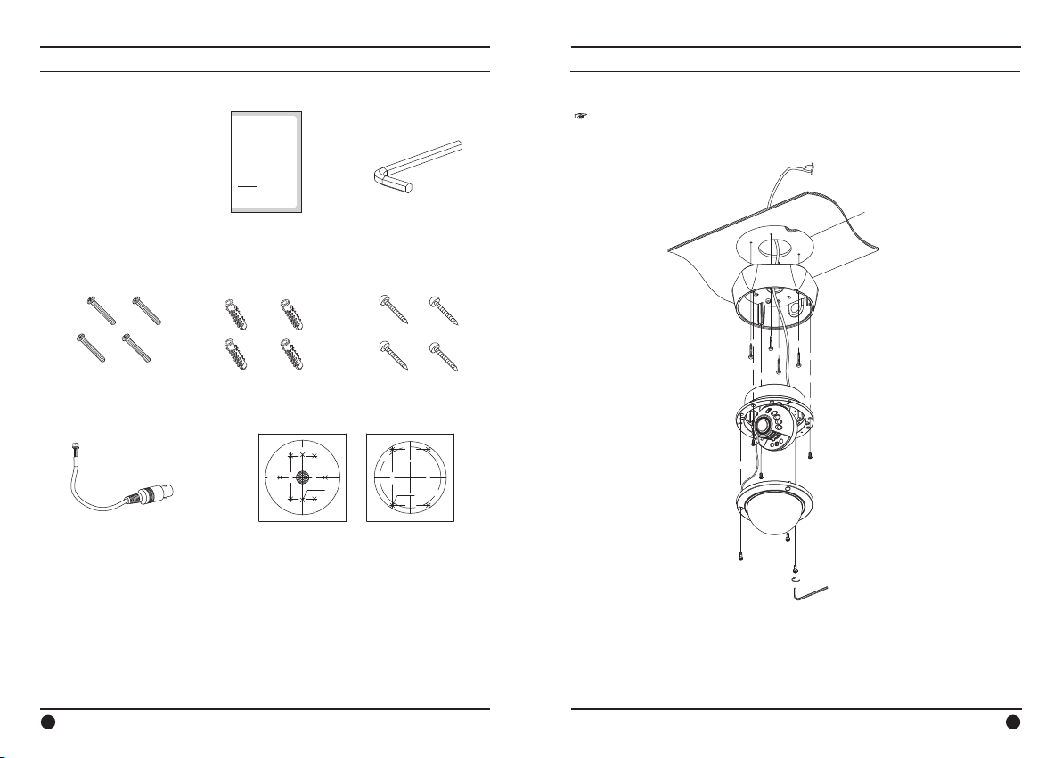
1) Installation overview
☞ NOTE
Be careful not to drop a Camera ball in installation.
A. Surface Mount
Super Night Vision IR
Instruction manual
Vandalproof Dome Camera 1EA
Super Night Vision
IR Vandalproof Dome Camera
INSTRUCTION MANUAL
Power Option
· 12VDC / 24VAC
Please read this manual carefully before installation and operation of the product.
1EA
L-Wrench (3.0mm)
1EA
Power
Video
Ceiling Tile
Drilling template
Surface Mount BASE
Tapping Screw
Ø4*30L-4EA
Fixed Screws
4EA
Extra Video output cable
1EA
6
Plastic anchor
4EA
88.0mm
83.5mm
<Surface> <Flush>
Tapping screws
SURFACE
83.5mm
8-DRILLING HOLE
Drilling template
1EA
109.0mm
4EA
4-DRILLING HOLE
Flush Mount Base
Camera Set
70.0mm
FLUSH
109.0mm
70.0mm
① Paste a Drilling Template on the ceiling or wall and drill screw points which will
be
done for installation.
② Fix a Surface Mounting Base by using Tapping Screws with Ø4 provided.
③ Fix a Flush Mounting Base to the Surface Mounting Base by using Fixed Screws
with
M4 provided.
Screw Fixed-3EA
PH MS M4*P0.7*8L
Dome-Ass'y
Socket Head Screw
M4*P0.7*10L-3EA
L-Wrencher 3.0mm
7
Page 5
5. Installation 5. Installation
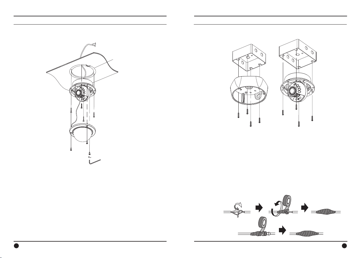
B. Flush Mount
Power
Video
Ceiling Tile
Drilling template
Flush Mount Base
Camera Set
Tapping Screw
Ø4*30L-4EA
Dome-Ass'y
Socket Head Screw
M4*P0.7*10L-3EA
L-Wrencher 3.0mm
① Paste a Drilling Template on the ceiling and drill screw points which will be done
for
installation.
② Fix a Flush Mounting Base on the ceiling by using Tapping Screws with Ø4
provided.
③ Point a Camera Ball to a desired direction and assemble a dome cover to the
Flush
Mounting Base with Socket Screws by using L-Wrench provided.
2) Junction Boxes
2 gang Junction box
(Industrial standard)
Surface Mount BASE
Fixed Screw-4EA
PH MS M4*P0.7*20L
① Fix a Surface Mounting Base or a Flush Mounting Base to 2 Gang Junction Box by
using Fixed Screws with M4 provided.
Flush Mount Base
3) Waterproof processing of cable connection
Make sure to use a butyl tape. (Do not use a sealing material on those parts)
① It is useful to connect the cable ends from camera to the extension cable for
waterproof.
② Connect and tape the power cables (Power-Power/Ground-Ground).
③ Bind the power cables together with the type.
When DC-Jack is used, tape the DC-DC joint.
④ Tape the BNC-BNC joint.
Power cable
(Red)
(Black)
Video output cable
8
9
Page 6
6. Features 6. Features
1) Key Features
· 1/3” Super HADⅡCCD
Clear focus at night with Anti-IR focus distortion technology
·
IR sensitive BW switching at night & true color at day
·
High resolution of 550TVL(Max)
·
Extremely reliable IR Protection technology
·
Long Viewable distance up to 20M at “0” Lux darkness
·
DC12V/AC24V Dual power
·
Weatherproof (IP66)
·
Tool-free 3-Axis
·
Surface / Flush mount compatible
·
The impact consolidation & incombustibleness (Body:aluminum /
·
Dome:polycarbonate)
2) Advantageous ways of installation
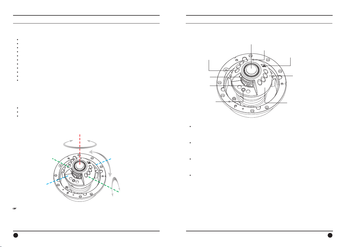
A. Tool-free 3-Axis mounting mechanism
Perfect Tri-axis!
Panning axis up to 360˚ degree
·
Tilting axis up to 180˚ degree
·
Rotation axis up to 360˚ degree
·
No need to use a tool for adjustment!
All adjustments are done quick and easy by hand!
Pan 360˚
Tilt
180˚
Rotation 360˚
B. Dome Inside View
Auto Iris Vari-focal Lens
VR
Ø8.0-IR Led
Focus Knob
Zoom Knob
CDS Sensor
· Focus Knob
LEFT Control : ∞
RIGHT Control : Near
Zoom Knob
·
LEFT Control : Tele
RIGHT Control : Wide
Extra video output
·
To enable an installer to check and adjust the camera set up via service monitor on
the spot.
DC IRIS CONTROL VR
·
To control a shutter speed of DC Iris lens.
EXTRA VIDEO
3-Axis Gimbal
Camera&Gimbal Cover
☞ NOTE
Angle adjustment from each of 3 different axis can be positioned to its maximum
angle of view so that the camera gets the full central picture at any location.
10
11
Page 7
6. Features 7. Trouble shooting guide
Problems
Trouble shooting
Nothing appears on the
screen.
Please check the power connection.
Please check the video signal line connection .
The video image is not
clear.
Pl ease check if the lens or t he outer glass is clean.
- Dirt or fingerprints on the lens can affect the im age
blooming or reflection. Gently wipe any dirt or
fingerprints off the lens or the glass with a soft cloth.
Please check and adjust contrast feature o f the monitor
Please check if the camera is exposed directly toward a
bright light, sunlight, or sun light reflecting area.
Please move the camera ’ s posit ion in this case.
The screen is dark.
Please check and adjust contrast feature of the monito r
If ther e is any interim equipment, set the Hi-z position
p roperl y and check the terminals.
Please check if the power supply is within the
specification.
- When the cabl e connection requires a long distance,
there may need a higher power supply or an additional
power/video amplification.
The camer a ’ s surface is too
hot and black strip e s
appear on the screen.
Please check if the power supply is regul a ted and is
within the standard requirement of the product.
The screen is flickering.
Please check if the camera is facing directly to ward
sunlight or fluorescent light.
IR beam is weak
Check if the distance of the cable installation is too long
or if the cable is not UL standard. Using a lower grade
cable or long distance cable installation can cause a
serious voltage drop. Please check the voltage output
level of the cable and change the power source in this
case. Make a special care not to supply too much
power over the camera as well.
C. Industrial standard mounting arrangement
1 / 2 "
Compatible to the industrial standard
2-gangs junction box
The mounting hole is compatible to
the standard electric junction box for
a quick and easy installation.
1/2” standard conduit hole
Pipe insertion from the side or from
the back of the dome is provided.
D. Additional service monitoring output
Additional Video Output terminal is provided
so that the installer can adjust the zoom/focus
and direction of camera on the spot.
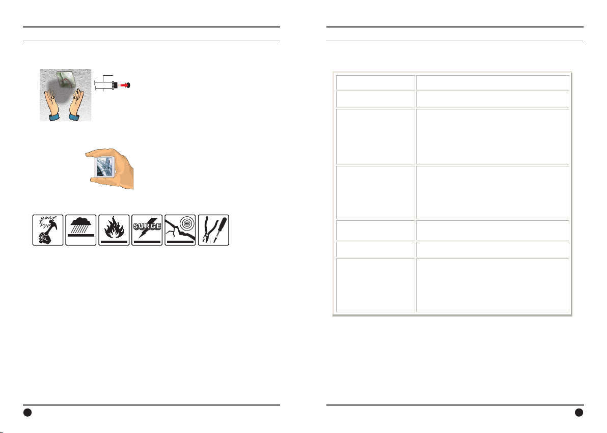
3) Perfect protection from all kinds of conceivable dangers
I p 6 6 H a r s h
W e a t h e r p r o o f
A. Vandal-proof
The body is made of 4.0mm thick die-cast and the dome made of 2.2mm thick
polycarbonate to be protective from a high impact of vandalism on the dome.
B. Tamper resistant
The dome is secured with a tailor-made stainless steel safety screws. (Option)
C. Free from Shock and Vibration
The tool-free internal 3-axis mounting mechanism is strong enough to hold the
camera set against severe vibration or shock on the dome.
D. Rust free against salty environment
The unit is fully protected from a salt mist environment with hard salty-water
resistant coating.
E. Dust and Moisture free (IP66 Weatherproof)
The unit is duly passed IP66 international weatherproof standard, allowing the
camera free from moisture and dust.
F. Fire resistant
Hard die-cast body and fully metallic internal camera mount mechanism are
designed to be totally protective from fire breaks or fire interception.
1/2” Conduit-holes are provided for fire resistant cable management.
12
Before sending the camera out for repair, check the items below. If the problem persists after
checking these items, contact your service center.
13
Page 8
8. Dimension (mm) 9. Specication
Eective Pixels
Digital Slow Shutter
Operating current
S/N ratio
Scanning system
Video output
Flush Mount
Surface Mount
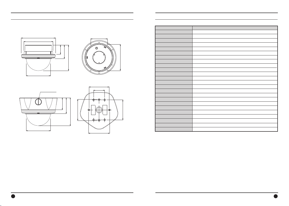
[5 9/16]Ø141.8
[4 3/4]Ø120.0
[3 15/16]Ø100.0
PT 1/2-14(15A)
[3 15/16]Ø100.0
Specication
Image sensor
[2 3/4]70.0
Eective Pixels
H.Resolution
Synchronizing system
[1 1/2]38.4
[2 1/4]57.0
[4 3/16]106.5
[4 5/16]109.0
Scanning system
Video output
S/N ratio
Min. Illumination
Back Light Compensation
White balance
Gain correction
Gamma correction
[3 5/16]83.5
[1 13/16]46.0
Smear Eect
Shutter speed
LED spectrum
IR Beam distance
MTBF
[1 15/16]49.5
[2 5/8]66.0
[3 7/16]88.0
[4 9/16]115.7
[3 5/16]83.5
Power source
Operation current
LENS
Operating Temp
Humidity
Measurement(mm)
[3 7/16]88.0
Weight(Approx.g)
Super Night Vision IR Vandalproof Dome Camera
1/3” Super HADCCD
NTSC : 768(H) X 494(V) PAL : 752(H) X 582(V)
550TVL (Max)
Internal
NTSC 525 Lines PAL 625 Lines 2:1 Interlaced
1.0Vp-p Composite. 75Ohms
More than 50dB(AGC o)
0.01Lux at F1.4 w/o LED, 0Lux with LED
Automatic
2100°K~9100°K Auto
-6dB~32dB Auto
r=0.45
0.005%
NTSC : 1/60~1/100,000sec, PAL : 1/50~1/100,000sec
850nm-Ø8 X 30° X 10EA
20M
20,000hours
DC12V/AC24V
DC12V : 400mA / AC24V : 200mA
3.3~12mm(F1.4) Auto DC Iris
14°F~122°F(-10°C~+50°C)
Within 90% RH
Flush Mount : 141.8(D) x 106.5(L), Surface Mount : 160(D) x 115.7(L)
1900
14
15
 Loading...