


www.vscom.de
VPNRouter Manual
Edition: Juli 2016
Edition: Juli 2016
Edition: Juli 2016
Edition: Juli 2016
Edition: Juli 2016
Edition: Juli 2016
Edition: Juli 2016
Edition: Juli 2016
Edition: Juli 2016
Edition: Juli 2016
Edition: Juli 2016
Edition: Juli 2016
Edition: Juli 2016
Edition: Juli 2016
Edition: Juli 2016
Edition: Juli 2016
Edition: Juli 2016
Tel: +49 40 528 401 0
Fax: +49 40 528 401 99
Web: www.visionsystems.de
Support: service@visionsystems.de

The software described in this manual is furnished under a license agreement and may be used
only in accordance with the terms of that agreement.
Copyright Notice
Copyright
prohibited.
©
2009-2018 Vision Systems. All rights reserved. Reproduction without permission is
Trademarks
VScom is a registered trademark of Vision Systems GmbH. All other trademarks and brands are
property of their rightful owners.
Disclaimer
Vision Systems reserves the right to make changes and improvements to its product without pro-
viding notice.
Vision Systems provides this document as is, without warranty of any kind, either expressed or
implied, including, but not limited to, its particular purpose. Vision Systems reserves the right
to make improvements and/or changes to this manual, or to the products and/or the programs
described in this manual, at any time.
Information provided in this manual is intended to be accurate and reliable. However, Vision
Systems assumes no responsibility for its use, or for any infringements on the rights of third parties
that may result from its use.
This product might include unintentional technical or typographical errors. Changes are periodically
made to the information herein to correct such errors, and these changes are incorporated into new
editions of the publication.
Juli 2016 VPNRouter Software Manual 2

Contents
Contents
1. Introduction 8
1.1. Manual Strategy and Details . . . . . . . . . . . . . . . . . . . . . . . . . . . . . . . 8
1.2. Typing Conventions . . . . . . . . . . . . . . . . . . . . . . . . . . . . . . . . . . . . 8
2. Hardware 9
2.1. Product Features . . . . . . . . . . . . . . . . . . . . . . . . . . . . . . . . . . . . . . 9
2.1.1. Ethernet . . . . . . . . . . . . . . . . . . . . . . . . . . . . . . . . . . . . . . . 10
2.1.2. USB . . . . . . . . . . . . . . . . . . . . . . . . . . . . . . . . . . . . . . . . . 10
2.1.3. CAN-Bus . . . . . . . . . . . . . . . . . . . . . . . . . . . . . . . . . . . . . . 10
2.1.4. Serial Ports . . . . . . . . . . . . . . . . . . . . . . . . . . . . . . . . . . . . . 11
2.1.5. Digital I/O . . . . . . . . . . . . . . . . . . . . . . . . . . . . . . . . . . . . . 11
2.1.6. I²C . . . . . . . . . . . . . . . . . . . . . . . . . . . . . . . . . . . . . . . . . . 11
2.1.7. WLAN . . . . . . . . . . . . . . . . . . . . . . . . . . . . . . . . . . . . . . . 11
3. Appearance 11
3.1. VPNRouter iR 5221 . . . . . . . . . . . . . . . . . . . . . . . . . . . . . . . . . . . . 12
3.2. VPNRouter iR 3220 . . . . . . . . . . . . . . . . . . . . . . . . . . . . . . . . . . . . 13
3.3. VPNRouter iR 2110 Front and Rear . . . . . . . . . . . . . . . . . . . . . . . . . . . 14
3.4. Mechanics for Mounting . . . . . . . . . . . . . . . . . . . . . . . . . . . . . . . . . . 14
4. Position of Connectors and Functions of VPNRouter iR 5221 and VPNRouter iR 3220 15
4.1. Power . . . . . . . . . . . . . . . . . . . . . . . . . . . . . . . . . . . . . . . . . . . . 15
4.1.1. Connection and Polarity . . . . . . . . . . . . . . . . . . . . . . . . . . . . . . 15
4.1.2. Grounding . . . . . . . . . . . . . . . . . . . . . . . . . . . . . . . . . . . . . . 17
4.2. WLAN Switch . . . . . . . . . . . . . . . . . . . . . . . . . . . . . . . . . . . . . . . 17
4.3. Digital I/O . . . . . . . . . . . . . . . . . . . . . . . . . . . . . . . . . . . . . . . . . 17
4.3.1. Digital Input . . . . . . . . . . . . . . . . . . . . . . . . . . . . . . . . . . . . 18
4.3.2. Digital Output . . . . . . . . . . . . . . . . . . . . . . . . . . . . . . . . . . . 18
4.3.3. I²C Interface . . . . . . . . . . . . . . . . . . . . . . . . . . . . . . . . . . . . 18
4.3.4. Auxiliary Power . . . . . . . . . . . . . . . . . . . . . . . . . . . . . . . . . . 18
4.4. Antenna Locations . . . . . . . . . . . . . . . . . . . . . . . . . . . . . . . . . . . . . 18
4.5. LED . . . . . . . . . . . . . . . . . . . . . . . . . . . . . . . . . . . . . . . . . . . . . 19
4.6. LAN . . . . . . . . . . . . . . . . . . . . . . . . . . . . . . . . . . . . . . . . . . . . . 19
4.7. WAN . . . . . . . . . . . . . . . . . . . . . . . . . . . . . . . . . . . . . . . . . . . . . 19
4.8. USB . . . . . . . . . . . . . . . . . . . . . . . . . . . . . . . . . . . . . . . . . . . . . 19
4.9. Serial . . . . . . . . . . . . . . . . . . . . . . . . . . . . . . . . . . . . . . . . . . . . . 20
4.9.1. DIP Conguration for Serial Ports . . . . . . . . . . . . . . . . . . . . . . . . 20
4.10. SD-Slot . . . . . . . . . . . . . . . . . . . . . . . . . . . . . . . . . . . . . . . . . . . 20
4.11. SIM-Slot . . . . . . . . . . . . . . . . . . . . . . . . . . . . . . . . . . . . . . . . . . . 21
4.12. Reset . . . . . . . . . . . . . . . . . . . . . . . . . . . . . . . . . . . . . . . . . . . . . 21
4.13. Console Port . . . . . . . . . . . . . . . . . . . . . . . . . . . . . . . . . . . . . . . . 21
4.14. USB/OTG . . . . . . . . . . . . . . . . . . . . . . . . . . . . . . . . . . . . . . . . . 21
4.15. CAN Bus . . . . . . . . . . . . . . . . . . . . . . . . . . . . . . . . . . . . . . . . . . 21
5. Position of Connectors and Functions of VPNRouter iR 2110 22
5.1. Power . . . . . . . . . . . . . . . . . . . . . . . . . . . . . . . . . . . . . . . . . . . . 22
5.1.1. Connection and Polarity . . . . . . . . . . . . . . . . . . . . . . . . . . . . . . 22
Juli 2016 VPNRouter Software Manual 3

Contents
5.1.2. Grounding . . . . . . . . . . . . . . . . . . . . . . . . . . . . . . . . . . . . . . 23
5.2. DIP Switches . . . . . . . . . . . . . . . . . . . . . . . . . . . . . . . . . . . . . . . . 23
5.3. Antenna Locations . . . . . . . . . . . . . . . . . . . . . . . . . . . . . . . . . . . . . 23
5.4. Reset . . . . . . . . . . . . . . . . . . . . . . . . . . . . . . . . . . . . . . . . . . . . . 23
5.5. WAN . . . . . . . . . . . . . . . . . . . . . . . . . . . . . . . . . . . . . . . . . . . . . 24
5.6. USB . . . . . . . . . . . . . . . . . . . . . . . . . . . . . . . . . . . . . . . . . . . . . 24
5.7. LED . . . . . . . . . . . . . . . . . . . . . . . . . . . . . . . . . . . . . . . . . . . . . 24
5.8. Serial . . . . . . . . . . . . . . . . . . . . . . . . . . . . . . . . . . . . . . . . . . . . . 24
5.9. LAN . . . . . . . . . . . . . . . . . . . . . . . . . . . . . . . . . . . . . . . . . . . . . 25
5.10. SD-Slot . . . . . . . . . . . . . . . . . . . . . . . . . . . . . . . . . . . . . . . . . . . 26
6. Logon to the Device 26
6.1. Connect to the Device . . . . . . . . . . . . . . . . . . . . . . . . . . . . . . . . . . . 26
6.1.1. Ethernet Cable to LAN Port . . . . . . . . . . . . . . . . . . . . . . . . . . . 26
6.2. Logon to Device Web Interface . . . . . . . . . . . . . . . . . . . . . . . . . . . . . . 26
7. Network 28
7.1. General . . . . . . . . . . . . . . . . . . . . . . . . . . . . . . . . . . . . . . . . . . . 29
7.1.1. Status . . . . . . . . . . . . . . . . . . . . . . . . . . . . . . . . . . . . . . . . 30
7.1.2. Local Network . . . . . . . . . . . . . . . . . . . . . . . . . . . . . . . . . . . 30
7.1.3. Internet Connection . . . . . . . . . . . . . . . . . . . . . . . . . . . . . . . . 31
7.1.3.1. by WAN Connection . . . . . . . . . . . . . . . . . . . . . . . . . . . 31
7.1.3.2. by 3G/4G Connection . . . . . . . . . . . . . . . . . . . . . . . . . . 32
7.1.3.3. by Wi Connection . . . . . . . . . . . . . . . . . . . . . . . . . . . 32
7.2. Wi . . . . . . . . . . . . . . . . . . . . . . . . . . . . . . . . . . . . . . . . . . . . . 33
7.2.1. Networks . . . . . . . . . . . . . . . . . . . . . . . . . . . . . . . . . . . . . . 33
7.2.1.1. WLAN scanned . . . . . . . . . . . . . . . . . . . . . . . . . . . . . 34
7.2.2. Adapter . . . . . . . . . . . . . . . . . . . . . . . . . . . . . . . . . . . . . . . 34
7.2.3. Local Network . . . . . . . . . . . . . . . . . . . . . . . . . . . . . . . . . . . 35
7.2.4. Conguration Procedures . . . . . . . . . . . . . . . . . . . . . . . . . . . . . 36
7.2.4.1. as Access Point . . . . . . . . . . . . . . . . . . . . . . . . . . . . . . 36
7.2.4.2. as Client . . . . . . . . . . . . . . . . . . . . . . . . . . . . . . . . . 36
7.3. 3G/4G . . . . . . . . . . . . . . . . . . . . . . . . . . . . . . . . . . . . . . . . . . . . 37
7.4. DHCP . . . . . . . . . . . . . . . . . . . . . . . . . . . . . . . . . . . . . . . . . . . . 38
7.4.1. DHCP-Server . . . . . . . . . . . . . . . . . . . . . . . . . . . . . . . . . . . . 38
7.4.2. Active Leases . . . . . . . . . . . . . . . . . . . . . . . . . . . . . . . . . . . . 39
7.4.2.1. Automatic Detection of local Devices . . . . . . . . . . . . . . . . . 39
7.4.3. Static Leases . . . . . . . . . . . . . . . . . . . . . . . . . . . . . . . . . . . . 39
7.4.4. Issues . . . . . . . . . . . . . . . . . . . . . . . . . . . . . . . . . . . . . . . . 41
8. System 41
8.1. General . . . . . . . . . . . . . . . . . . . . . . . . . . . . . . . . . . . . . . . . . . . 42
8.2. Language . . . . . . . . . . . . . . . . . . . . . . . . . . . . . . . . . . . . . . . . . . 43
8.3. Admin Password . . . . . . . . . . . . . . . . . . . . . . . . . . . . . . . . . . . . . . 43
8.4. Backup/Restore . . . . . . . . . . . . . . . . . . . . . . . . . . . . . . . . . . . . . . . 43
8.4.1. Download backup . . . . . . . . . . . . . . . . . . . . . . . . . . . . . . . . . . 44
8.4.2. Reset to defaults . . . . . . . . . . . . . . . . . . . . . . . . . . . . . . . . . . 44
8.4.3. Restore backup . . . . . . . . . . . . . . . . . . . . . . . . . . . . . . . . . . . 44
8.5. Flash Firmware . . . . . . . . . . . . . . . . . . . . . . . . . . . . . . . . . . . . . . . 44
8.6. Reboot . . . . . . . . . . . . . . . . . . . . . . . . . . . . . . . . . . . . . . . . . . . . 45
Juli 2016 VPNRouter Software Manual 4

List of Figures
9. Services 46
9.1. GPIO . . . . . . . . . . . . . . . . . . . . . . . . . . . . . . . . . . . . . . . . . . . . 47
9.2. NetCom . . . . . . . . . . . . . . . . . . . . . . . . . . . . . . . . . . . . . . . . . . . 48
9.3. NET-CAN . . . . . . . . . . . . . . . . . . . . . . . . . . . . . . . . . . . . . . . . . . 51
9.4. SimpleVPN . . . . . . . . . . . . . . . . . . . . . . . . . . . . . . . . . . . . . . . . . 52
9.4.1. Conguration transfer . . . . . . . . . . . . . . . . . . . . . . . . . . . . . . . 53
9.4.1.1. New conguration . . . . . . . . . . . . . . . . . . . . . . . . . . . . 54
9.4.1.2. Existing congurations . . . . . . . . . . . . . . . . . . . . . . . . . 55
9.4.2. Conguration . . . . . . . . . . . . . . . . . . . . . . . . . . . . . . . . . . . . 57
9.4.2.1. Server Settings . . . . . . . . . . . . . . . . . . . . . . . . . . . . . . 58
9.4.2.1.1. Public Server IPv4 Adress or Domain Name . . . . . . . . . 58
9.4.2.1.2. Server Mode and Client Mode . . . . . . . . . . . . . . . . 58
9.4.2.1.3. Server LAN IPv4-Address . . . . . . . . . . . . . . . . . . 61
9.4.2.1.4. Server LAN Netmask . . . . . . . . . . . . . . . . . . . . . 62
9.4.2.1.5. Transport Protocol . . . . . . . . . . . . . . . . . . . . . . . 62
9.4.2.1.6. Port . . . . . . . . . . . . . . . . . . . . . . . . . . . . . . . 63
9.4.2.1.7. Allow Client-to-Client trac . . . . . . . . . . . . . . . . . 63
9.4.2.1.8. Upload Server Certicates and Keys . . . . . . . . . . . . . 63
9.4.2.2. Add a Client . . . . . . . . . . . . . . . . . . . . . . . . . . . . . . . 64
9.4.2.3. Client Settings . . . . . . . . . . . . . . . . . . . . . . . . . . . . . . 65
9.4.2.3.1. Client LAN IPv4-Address . . . . . . . . . . . . . . . . . . . 65
9.4.2.3.2. Client LAN IPv4-Netmask . . . . . . . . . . . . . . . . . . 65
9.4.2.3.3. Upload Client Certicates and Keys . . . . . . . . . . . . . 65
9.4.2.4. Delete a Client . . . . . . . . . . . . . . . . . . . . . . . . . . . . . . 66
9.4.3. Generate Certicates and Keys . . . . . . . . . . . . . . . . . . . . . . . . . . 67
A. History 68
B. License 68
List of Figures
1. Appearance VPNRouter iR 5221 . . . . . . . . . . . . . . . . . . . . . . . . . . . . . 12
2. Appearance VPNRouter iR 3220 . . . . . . . . . . . . . . . . . . . . . . . . . . . . . 13
4. Mounting Positions VPNRouter iR 5221/VPNRouter iR 3220 . . . . . . . . . . . . . 14
3. Appearance VPNRouter iR 2110 . . . . . . . . . . . . . . . . . . . . . . . . . . . . . 14
6. Power Connector . . . . . . . . . . . . . . . . . . . . . . . . . . . . . . . . . . . . . . 15
5. Mounting Positions VPNRouter iR 2110 . . . . . . . . . . . . . . . . . . . . . . . . . 16
7. PE Screw . . . . . . . . . . . . . . . . . . . . . . . . . . . . . . . . . . . . . . . . . . 17
8. WLAN Switch . . . . . . . . . . . . . . . . . . . . . . . . . . . . . . . . . . . . . . . 17
9. Digital Input / Output Connector . . . . . . . . . . . . . . . . . . . . . . . . . . . . . 17
10. Antenna location . . . . . . . . . . . . . . . . . . . . . . . . . . . . . . . . . . . . . . 18
11. Front LED . . . . . . . . . . . . . . . . . . . . . . . . . . . . . . . . . . . . . . . . . . 19
12. LAN ports . . . . . . . . . . . . . . . . . . . . . . . . . . . . . . . . . . . . . . . . . . 19
13. WAN port and USB connectors . . . . . . . . . . . . . . . . . . . . . . . . . . . . . . 19
14. COM Ports . . . . . . . . . . . . . . . . . . . . . . . . . . . . . . . . . . . . . . . . . 20
15. DIP Switches . . . . . . . . . . . . . . . . . . . . . . . . . . . . . . . . . . . . . . . . 20
16. SD and SIM Slot . . . . . . . . . . . . . . . . . . . . . . . . . . . . . . . . . . . . . . 20
17. Reset Button . . . . . . . . . . . . . . . . . . . . . . . . . . . . . . . . . . . . . . . . 21
Juli 2016 VPNRouter Software Manual 5

List of Figures
18. Console Port . . . . . . . . . . . . . . . . . . . . . . . . . . . . . . . . . . . . . . . . 21
19. OTG . . . . . . . . . . . . . . . . . . . . . . . . . . . . . . . . . . . . . . . . . . . . . 21
20. CAN Bus . . . . . . . . . . . . . . . . . . . . . . . . . . . . . . . . . . . . . . . . . . 22
21. Power Connector . . . . . . . . . . . . . . . . . . . . . . . . . . . . . . . . . . . . . . 22
22. PE Screw . . . . . . . . . . . . . . . . . . . . . . . . . . . . . . . . . . . . . . . . . . 23
23. DIP Switches . . . . . . . . . . . . . . . . . . . . . . . . . . . . . . . . . . . . . . . . 23
24. Antenna location . . . . . . . . . . . . . . . . . . . . . . . . . . . . . . . . . . . . . . 23
25. Reset Button . . . . . . . . . . . . . . . . . . . . . . . . . . . . . . . . . . . . . . . . 23
26. WAN Port . . . . . . . . . . . . . . . . . . . . . . . . . . . . . . . . . . . . . . . . . . 24
27. USB Connector . . . . . . . . . . . . . . . . . . . . . . . . . . . . . . . . . . . . . . . 24
28. Front LED . . . . . . . . . . . . . . . . . . . . . . . . . . . . . . . . . . . . . . . . . . 24
29. COM Port . . . . . . . . . . . . . . . . . . . . . . . . . . . . . . . . . . . . . . . . . . 25
30. LAN Port . . . . . . . . . . . . . . . . . . . . . . . . . . . . . . . . . . . . . . . . . . 25
31. SD Slot . . . . . . . . . . . . . . . . . . . . . . . . . . . . . . . . . . . . . . . . . . . 26
32. Logon Mask . . . . . . . . . . . . . . . . . . . . . . . . . . . . . . . . . . . . . . . . . 26
33. Pull Down Menu . . . . . . . . . . . . . . . . . . . . . . . . . . . . . . . . . . . . . . 27
34. Save Conguration Changes . . . . . . . . . . . . . . . . . . . . . . . . . . . . . . . . 27
35. Menu Network . . . . . . . . . . . . . . . . . . . . . . . . . . . . . . . . . . . . . . . 28
36. Network General Overview . . . . . . . . . . . . . . . . . . . . . . . . . . . . . . . . . 29
37. Status of Network Interfaces . . . . . . . . . . . . . . . . . . . . . . . . . . . . . . . . 30
38. Local Network Conguration . . . . . . . . . . . . . . . . . . . . . . . . . . . . . . . 30
39. WAN connection . . . . . . . . . . . . . . . . . . . . . . . . . . . . . . . . . . . . . . 31
40. 3G/4G Conguration . . . . . . . . . . . . . . . . . . . . . . . . . . . . . . . . . . . . 32
41. Wi Conguration . . . . . . . . . . . . . . . . . . . . . . . . . . . . . . . . . . . . . 32
42. Wi Networks . . . . . . . . . . . . . . . . . . . . . . . . . . . . . . . . . . . . . . . . 33
43. Wi Scan Results . . . . . . . . . . . . . . . . . . . . . . . . . . . . . . . . . . . . . . 34
44. Wi Radio Parameters . . . . . . . . . . . . . . . . . . . . . . . . . . . . . . . . . . . 34
45. Wi Network . . . . . . . . . . . . . . . . . . . . . . . . . . . . . . . . . . . . . . . . 35
46. 3G/4G Interface . . . . . . . . . . . . . . . . . . . . . . . . . . . . . . . . . . . . . . 37
47. DHCP Address Range . . . . . . . . . . . . . . . . . . . . . . . . . . . . . . . . . . . 38
48. Active Leases . . . . . . . . . . . . . . . . . . . . . . . . . . . . . . . . . . . . . . . . 39
49. Static Leases . . . . . . . . . . . . . . . . . . . . . . . . . . . . . . . . . . . . . . . . 39
50. Menu System . . . . . . . . . . . . . . . . . . . . . . . . . . . . . . . . . . . . . . . . 41
51. System General Information . . . . . . . . . . . . . . . . . . . . . . . . . . . . . . . . 42
52. Select Language . . . . . . . . . . . . . . . . . . . . . . . . . . . . . . . . . . . . . . . 43
53. Set Admin Password . . . . . . . . . . . . . . . . . . . . . . . . . . . . . . . . . . . . 43
54. Backup/Restore . . . . . . . . . . . . . . . . . . . . . . . . . . . . . . . . . . . . . . . 44
55. Flash Firmware . . . . . . . . . . . . . . . . . . . . . . . . . . . . . . . . . . . . . . . 44
56. Reboot the Device . . . . . . . . . . . . . . . . . . . . . . . . . . . . . . . . . . . . . 45
57. Menu Services . . . . . . . . . . . . . . . . . . . . . . . . . . . . . . . . . . . . . . . . 46
58. GPIO Control . . . . . . . . . . . . . . . . . . . . . . . . . . . . . . . . . . . . . . . . 47
59. NetCom Conguration . . . . . . . . . . . . . . . . . . . . . . . . . . . . . . . . . . . 48
60. Conguration RFC2217 . . . . . . . . . . . . . . . . . . . . . . . . . . . . . . . . . . 49
61. Conguration TCP raw . . . . . . . . . . . . . . . . . . . . . . . . . . . . . . . . . . 50
62. NET-CAN Conguration . . . . . . . . . . . . . . . . . . . . . . . . . . . . . . . . . 51
63. Overview SimpleVPN . . . . . . . . . . . . . . . . . . . . . . . . . . . . . . . . . . . 52
64. Area conguration transfer . . . . . . . . . . . . . . . . . . . . . . . . . . . . . . . . 53
65. Overview transfer SimpleVPN . . . . . . . . . . . . . . . . . . . . . . . . . . . . . . 53
66. Topology . . . . . . . . . . . . . . . . . . . . . . . . . . . . . . . . . . . . . . . . . . 57
Juli 2016 VPNRouter Software Manual 6

List of Figures
67. SimpleVPN- Public Server IPv4 Address . . . . . . . . . . . . . . . . . . . . . . . . 58
68. Server and Client Mode . . . . . . . . . . . . . . . . . . . . . . . . . . . . . . . . . . 58
69. Internet Router . . . . . . . . . . . . . . . . . . . . . . . . . . . . . . . . . . . . . . . 59
70. VPN Gateway . . . . . . . . . . . . . . . . . . . . . . . . . . . . . . . . . . . . . . . . 60
71. SimpleVPN - Server IPv4-Address . . . . . . . . . . . . . . . . . . . . . . . . . . . . 61
72. Dierence between public and private addresses . . . . . . . . . . . . . . . . . . . . 61
73. SimpleVPN - Server LAN Netmask . . . . . . . . . . . . . . . . . . . . . . . . . . . . 62
74. SimpleVPN - Transport Protocol . . . . . . . . . . . . . . . . . . . . . . . . . . . . . 62
75. OpenVPN Port . . . . . . . . . . . . . . . . . . . . . . . . . . . . . . . . . . . . . . . 63
76. OpenVPN client-to-client . . . . . . . . . . . . . . . . . . . . . . . . . . . . . . . . . 63
77. Add a Client . . . . . . . . . . . . . . . . . . . . . . . . . . . . . . . . . . . . . . . . 64
78. Client overview . . . . . . . . . . . . . . . . . . . . . . . . . . . . . . . . . . . . . . . 64
79. SimpleVPN - Client LAN IPv4-Address . . . . . . . . . . . . . . . . . . . . . . . . . 65
80. SimpleVPN - Client LAN Netmask . . . . . . . . . . . . . . . . . . . . . . . . . . . . 65
81. Client delete . . . . . . . . . . . . . . . . . . . . . . . . . . . . . . . . . . . . . . . . . 66
82. Generate Certicates and Keys . . . . . . . . . . . . . . . . . . . . . . . . . . . . . . 67
83. Buttons Generate and Generate DH Parameters . . . . . . . . . . . . . . . . . . . . . 67
Juli 2016 VPNRouter Software Manual 7
1 Introduction
1. Introduction
The system VPNRouter impresses with its quality and robustness. This makes it possible to use the
VPNRouter in dierent areas. Of course, the VPNRouter also has the latest security features such
as a rewall or VPN. In general there is a trade-o between ease-of-use and security, VPNRouter
optimizes this. The system is easy to install and use, but at the same time oers security given by
strong encryption standards.
1.1. Manual Strategy and Details
This manual covers the conguration of the VPNRouter in detail.
1.2. Typing Conventions
When describing the manual has to reference some components visible on the screen. For better
identication the reference is supported by showing the text in certain styles.
Software text
User Input
of a typewriter represents this input.
[A Button]
are represented by the name on them. The name is written in typewriter style on silver
background, and surrounded by brackets.
[A Button]
are again represented by the name on them. This time the name is written in typewriter style
white colour on blue background, still surrounded by brackets.
Component
written in bold.
is written in a slanted style. Such item represents
Input forms require the user to
Controling the software will also require to click some
Further there are some
The manual will reference some components on the Device, then the
type some data
[blue buttons]
to control the web interface. These buttons
text output
on the keyboard. Text written in style
[buttons]
written on the screen.
. These buttons
name of it
is
Juli 2016 VPNRouter Software Manual 8
2 Hardware
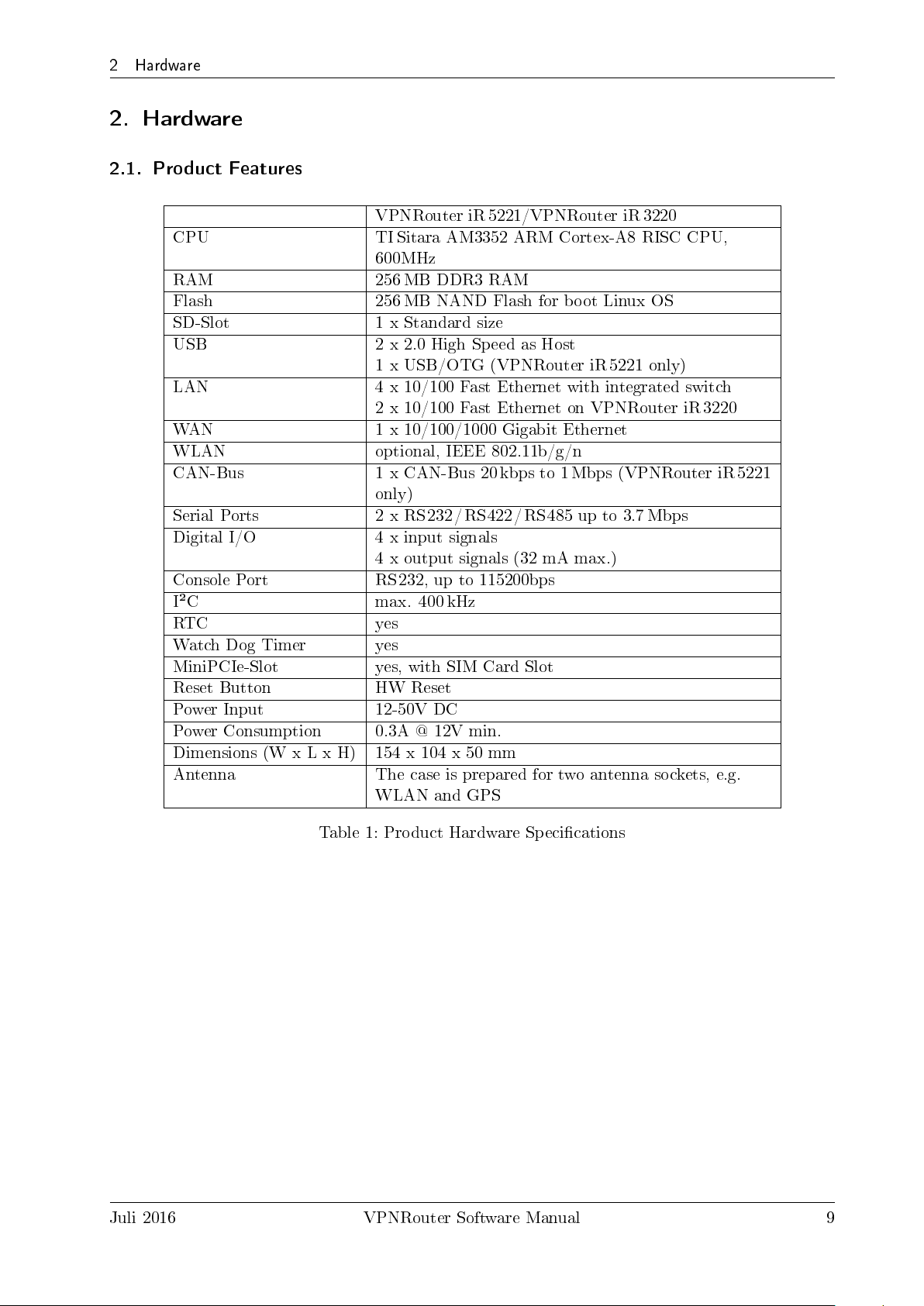
2. Hardware
2.1. Product Features
CPU TI Sitara AM3352 ARM Cortex-A8 RISC CPU,
RAM 256 MB DDR3 RAM
Flash 256 MB NAND Flash for boot Linux OS
SD-Slot 1 x Standard size
USB 2 x 2.0 High Speed as Host
LAN 4 x 10/100 Fast Ethernet with integrated switch
WAN 1 x 10/100/1000 Gigabit Ethernet
WLAN optional, IEEE 802.11b/g/n
CAN-Bus 1 x CAN-Bus 20 kbps to 1 Mbps (VPNRouter iR 5221
Serial Ports 2 x RS232/RS422/RS485 up to 3.7Mbps
Digital I/O 4 x input signals
Console Port RS232, up to 115200bps
I²C max. 400 kHz
RTC yes
Watch Dog Timer yes
MiniPCIe-Slot yes, with SIM Card Slot
Reset Button HW Reset
Power Input 12-50V DC
Power Consumption 0.3A @ 12V min.
Dimensions (W x L x H) 154 x 104 x 50 mm
Antenna The case is prepared for two antenna sockets, e.g.
VPNRouter iR 5221/VPNRouter iR 3220
600MHz
1 x USB/OTG (VPNRouter iR 5221 only)
2 x 10/100 Fast Ethernet on VPNRouter iR 3220
only)
4 x output signals (32 mA max.)
WLAN and GPS
Table 1: Product Hardware Specications
Juli 2016 VPNRouter Software Manual 9

2 Hardware
CPU TI Sitara AM3352 ARM Cortex-A8 RISC CPU,
RAM 256 MB DDR3 RAM
Flash 256 MB NAND Flash for boot Linux OS
SD-Slot 1 x external, size microSD
USB 1 x 2.0 High Speed as Host
LAN 1 x 10/100 Fast Ethernet
WAN 1 x 10/100/1000 Gigabit Ethernet
WLAN optional, IEEE 802.11b/g/n
Serial Ports 1 x RS232/RS422/RS485 up to 3.7Mbps
Console Port TTL internal, up to 115200bps
RTC yes
Watch Dog Timer yes
Reset Button HW Reset
Power Input 9-54V DC
Power Consumption 0.2A @ 12V min.
Dimensions (W x L x H) 115 x 73 x 25 mm
Antenna The case provides two positions for an antenna socket
VPNRouter iR 2110
600MHz
adapter to USB available
Table 2: Product Hardware Specications
2.1.1. Ethernet
Two independent ports for Ethernet are available in VPNRouter, with separate MAC Addresses.
One port is implemented as GigaLAN for 10/100/1000 Mbit/s, the other provides an internal Eth-
ernet switch for Fast Ethernet function 10/100 Mbit/s. The VPNRouter iR 5221 provides four Fast
Ethernet ports, on VPNRouter iR 3220 there are two of them and VPNRouter iR 2110 has only one
missing the Ethernet switch.
2.1.2. USB
Two USB Host ports for USB 2.0 High Speed allow to connect any devices. The VPNRouter iR 2110
has only one port. Support for certain WLAN and 3G/4G adapters is available.
On VPNRouter iR 5221 only: there is one extra port type USB 2.0 OTG for Host and Device
operation mode.
2.1.3. CAN-Bus
On VPNRouter iR 5221 only: one CAN port for CAN 2.0A and 2.0B is available. The port operates
from 20 kbit/s up to 1 Mbit/s.
Juli 2016 VPNRouter Software Manual 10

3 Appearance
2.1.4. Serial Ports
Two serial ports are provided in RS232/422/485 modes that can be congured by software or by
DIP switch where as the VPNRouter iR 2110 has only one serial port congurable by software. For
the detailed information about the supported modes refer to the Table 3.
RS232 RS422 RS485
Modes full duplex full duplex 2-wire: half duplex, without echo
4-wire: full duplex
Signals TxD, RxD, RTS, CTS,
DTR, DSR, DCD, RI,
GND
Data
Direction
Control
Speed up to 921.6 / 1000kbps up to 3.7 Mbps up to 3.7 Mbps
Table 3: Serial Interface Specications
Tx+/-, Rx+/-,
GND
2-wire: Data+/-, GND
4-wire: Tx+/-, Rx+/-, GND
by driver, via RTS
2.1.5. Digital I/O
Four input and four output signals at TTL level are provided. For input signals the change of at
least one input signal generates an interrupt. See Section 4.3 on page 17 for electrical characteristics.
The VPNRouter iR 2110 does not have these.
2.1.6. I²C
One port for external I²C function is provided. The signals originate in a repeater, to protect the
internal circuits from external misconguration or signal shorting. The VPNRouter iR 2110 does
not have this port.
2.1.7. WLAN
The VPNRouter is available with an optional built-in WLAN function as of IEEE 802.11b/g/n for
wireless connection.
3. Appearance
This is how the VPNRouter systems look like on the top, front and bottom sides.
Juli 2016 VPNRouter Software Manual 11

3 Appearance
3.1. VPNRouter iR 5221
(a) Top View (b) Front View (c) Bottom View
Figure 1: Appearance VPNRouter iR 5221
Juli 2016 VPNRouter Software Manual 12

3 Appearance
3.2. VPNRouter iR 3220
(a) Top View (b) Front View (c) Bottom View
Figure 2: Appearance VPNRouter iR 3220
The VPNRouter iR 3220 provides two ports for LAN, the CAN Bus connector and the USB/OTG
port are not implemented.
Juli 2016 VPNRouter Software Manual 13

3 Appearance
Figure 4: Mounting Positions VPNRouter iR 5221/VPNRouter iR 3220
3.3. VPNRouter iR 2110 Front and Rear
(a) Front View
(b) Rear View
Figure 3: Appearance VPNRouter iR 2110
The front side has the Gigabit WAN port and USB. Then there is the serial port and the Fast
Ethernet LAN port. Small on the lower right is the slot for a microSD card.
The rear side provides the socket for the terminal block power connector. On this side also a DIN
Rail clamp may be mounted. The DIP switches dene the operation mode of the serial port. There
is a possible location for a WLAN antenna. The Reset button is pushed by a small prick.
3.4. Mechanics for Mounting
This are the positions of screws for mounting. The groups of three on the left and right (actually
top and bottom) hold the metal plates for wall mounting.
Juli 2016 VPNRouter Software Manual 14

4 Position of Connectors and Functions of VPNRouter iR5221 and VPNRouter iR 3220
The group of four in the middle is for the DIN Rail mounting clamp. This may be mounted in
standard orientation, or turned by 90°to provide for a (seldom used) horizontal xture on the DIN
Rail.
Figure 5a is a reference for the positions of front side connectors. It is for demonstration only.
Figure 5b shows the positions of screws for xing. Note, this is upside down with respect to the
front side. The two M3 screw positions in the middle allow to x an DIN Rail clamp. There is also
the position of a possible antenna socket near the Reset button.
4. Position of Connectors and Functions of VPNRouter iR 5221 and
VPNRouter iR 3220
First the connectors and functions located on the top side of VPNRouter iR 5221 and VPN-
Router iR 3220 are described. The next components are those on the front side, nally followed by
those on the bottom side.
4.1. Power
The VPNRouter device is powered by a single power supply in a wide range from 12 V to 50 V
DC. A suitable power supply adapter is available as add-on component, and part of the starter kit
package. Connect the cable to the power jack at the top side of VPNRouter, and plug the adapter
into the socket. The Power LED (red) on VPNRouter will light. You can connect a power supply
of your choice, providing the technical requirements are met.
Warning:
The wire size must follow the maximum current specications. The maximum possible current in
the power wires as well as in the common wires must be taken under consideration. If the current
rises above the maximum ratings, the wiring can overheat, causing serious damage to your equip-
ment. When powered, the VPNRouter's internal components generate heat, and consequently
the outer case may feel warm to the touch.
4.1.1. Connection and Polarity
Power is connected via three clamps on a terminal block, located on the top side of VPNRouter iR 5221/VPNRouter iR3220.
Warning:
damage the CAN bus port.
disconnect the VPNRouter from power supply before performing installation or wiring.
do not confuse the CAN connector at the bottom side for power input. Such may
V+ and V- are clamps for DC volt-
Clamp
Function
Table 4: Power Connector
Juli 2016 VPNRouter Software Manual 15
3 2 1
PE V- V+
age supply. PE is the clamp to con-
nect the case and shields of con-
nection cables to Protective Earth.
PE is internally connected to logic
ground, which is on the level of V-
supply line.
Figure 6: Power Connector

4 Position of Connectors and Functions of VPNRouter iR5221 and VPNRouter iR 3220
(a) Front Side
(b) Rear Side
Figure 5: Mounting Positions VPNRouter iR 2110
Juli 2016 VPNRouter Software Manual 16

4 Position of Connectors and Functions of VPNRouter iR5221 and VPNRouter iR 3220
Attention:
Never connect the Terminal block for power supply in reversed direction, i.e. turned
by 180°. This would connect the power between V- (logic ground) and case/protective ground.
High current is the result, causing damage inside the system.
4.1.2. Grounding
Grounding and wire routing help limit the eects of noise due to electromagnetic interference (EMI).
Run the ground connection from the ground screw to the grounding surface prior to connecting
devices.
In noisy environments the case of VPNRouter shall be directly connected to
Protective Earth. This is the purpose of the dedicated PE Screw on the case
top/rear side.
Figure 7: PE Screw
4.2. WLAN Switch
The WLAN switch on the top side is used to disable the WLAN function.
Provided the VPNRouter is equipped with a WLAN module. Otherwise
software may just read this switch for other purposes.
Figure 8: WLAN
Switch
4.3. Digital I/O
The functions of Digital Input and Output are located on the 13 clamp terminal block on the top
side of VPNRouter. Also available on this terminal block is the function of I²C and an auxiliary
power output.
1 2 3 4 5 6
+5V IN 0 IN1 IN 2 IN 3 GND
(a) Input connects
7 8 9 10
OUT 0 OUT 1 OUT2 OUT3
(b) Output connects
11 12 13
GND SDA SCL
(c) I²C connects
Table 5: Digital Input/Output: Connector
Figure 9: Digital
Input /Output
Connector
Juli 2016 VPNRouter Software Manual 17

4 Position of Connectors and Functions of VPNRouter iR5221 and VPNRouter iR 3220
4.3.1. Digital Input
The VPNRouter provides four digital input channels. The signals IN 0 to IN 3 are located on clamps
2 to 5 of the terminal block, the reference GND is on clamp 6. A signal change on an input channel
will generate an interrupt.
Input High TTL level (2.0 to 5.0V)
Input Low TTL level (0.0 to 0.8V)
Table 6: Digital Input: Electrical Characteristics
4.3.2. Digital Output
The VPNRouter provides four digital output channels. The signals OUT 0 to OUT 3 are located on
clamps 7 to 10 of the terminal block, the reference GND is on clamp 6 and 11. The output ports
can source some milliAmpere output in High status, with decreasing voltage when the current rises.
In Low status they can sink signicant current, enough to drive small relays.
Output High Source 32mA@TTL (2.0 to 5.0V)
Output Low Sink 64mA@TTL (0.0 to 0.6V)
Table 7: Digital Output: Electrical Characteristics
4.3.3. I²C Interface
The I²C interface operates with a maximum frequency of 400 kHz (Fast Mode). The connector
for I²C is located on the terminal digital I/O block and has three contacts: SCL, SDA and GND
(clamps 11 to 13). When required the I²C device can be powered with the VCC auxiliary output
of the digital I/O terminal block.
4.3.4. Auxiliary Power
+5V is an auxiliary power output of 5V DC, for max. 500 milliAmpere. This may be used to drive
special driver circuits connected at Digital-I/O. For example +5V may drive a relay controlled by
the output signals, or power a small I²C-controlled display. The GND for auxiliary power is on
clamps 6 and 11.
4.4. Antenna Locations
The VPNRouter is prepared for adding two antenna sockets of the usual SMA
type. These may be used for functions like WLAN, UMTS/LTE wireless or
GPS receivers. The positions are covered by plastic caps. Both antenna
positions are on the top side of VPNRouter iR 5221/VPNRouter iR 3220.
Figure 10: Antenna
location
Juli 2016 VPNRouter Software Manual 18

4 Position of Connectors and Functions of VPNRouter iR5221 and VPNRouter iR 3220
4.5. LED
The front side starts with a group of four LEDs.
PWR
3G
WIFI
APP
(Red) lights when power is applied to the VPNRouter. System soft-
ware may generate short blinks for certain events.
(Yellow) is controlled by a UMTS/LTE modem card in the mini PCIe
expansion slot.
(Blue) signals operation status of WLAN function.
(Green) is free to use by customers application, e.g. as some ready
light.
4.6. LAN
The rst Ethernet port in VPNRouter is for 10/100 Mbps Fast
Ethernet. This connects to an internal Ethernet switch, with 2
(VPNRouter iR 3220) or 4 (VPNRouter iR 5221) external connec-
tors. Devices or systems connected to these ports can communicate
with each other, without involving the CPU of VPNRouter.
Each of the LAN ports are the usual RJ45. When the connect is
done the Link LED on RJ45 (right) will light. When data trac
occurs on the network, this LED will blink. It depends on your
network or devices whether a 100 Mbit or a 10 Mbit connect will be
established. The Speed LED (left) lights for 100Mbps connections.
Figure 11: Front
LED
Figure 12: LAN ports
4.7. WAN
The second Ethernet port in VPNRouter is for 10/100/1000 Mbps
Gigabit Ethernet. The connector is the usual RJ45, integrated
with USB ports.
When the connect is done the Link LED on RJ45 (green, left)
will light. When data trac occurs on the network, this LED will
blink. It depends on your network or devices whether a 1000 Mbit,
a 100 Mbit or a 10 Mbit connect will be established. The Speed
LED (yellow, right) lights for 10 and 100 Mbps connections.
This Ethernet interfaces supports Auto-MDI(X) feature.
Figure 13: WAN port and
USB connectors
4.8. USB
The VPNRouter provides two USB 2.0 Host interfaces. They can be used for Mass Storage Devices,
like Flash- or Hard Drive, Bluetooth and WLAN adapters etc.
The ports are integrated with the Gigabit Ethernet WAN port, see gure 13.
Juli 2016 VPNRouter Software Manual 19

4 Position of Connectors and Functions of VPNRouter iR5221 and VPNRouter iR 3220
4.9. Serial
VPNRouter iR 5221 and VPNRouter iR 3220 provide two DSub-9 male connectors. All three modes
of operating RS232, RS422 or RS485 are entirely congurable by software. For the pinout refer to
the Table 8. If the conguration by software is not used, the default operation mode of each port
is congured by a DIP switch. The DIP switch may be overridden by software, if the user chooses
to do so. Check section??on page ?? for details.
Pin RS232 RS422 RS485 2-wire
1 DCD Tx- (A) Data- (A)
2 RxD Tx+ (B) Data+ (B)
3 TxD Rx+ (B)
4 DTR Rx- (A)
5 GND GND GND
6 DSR
7 RTS
8 CTS
9 RI
Figure 14: COM
Ports
Table 8: Serial DSub-9 Pinout
Please note the function of the GND signal in RS422 and RS485 modes: this signal must also be
connected between the serial devices. So in reality a 2-wire and a 4-wire connection need 3 wire
and 5 wire respectively. With the exception of very special congurations, a serial connection in
RS422/RS485 mode without GND connection violates the specications for RS422 and RS485
standards.
4.9.1. DIP Conguration for Serial Ports
The right side of the case has a small opening slit. This is provided to access
the DIP switches for serial conguration. With a small pen or screw driver
the conguration can be changed without opening the case.
The current setting of the switches is readable by software. If the user or
software decides to do this, the software can override the active conguration,
i.e. change the operation mode. Please check section??on page ?? for details
about this function.
Figure 15: DIP
Switches
4.10. SD-Slot
The VPNRouter provides an SD-Slot on the front side of the case, for cards
in standard size. The slot supports cards as SD 2.0 or SDHC type, to allow
up to 32 GB of capacity. Class 10 cards are supported as well.
If an operating system is installed on the SD Card, the VPNRouter will boot
this software.
Figure 16: SD and
SIM Slot
Juli 2016 VPNRouter Software Manual 20

4 Position of Connectors and Functions of VPNRouter iR5221 and VPNRouter iR 3220
4.11. SIM-Slot
A SIM-Slot is located right next to the SD-Slot, see gure 16 on the preceding page. A Mini SIM
card in this slot is accessed by a UMTS/LTE modem card in the mini PCIe expansion slot.
4.12. Reset
The Reset button is the front most component on the bottom side of VPNRouter.
With Reset button you can restart the VPNRouter without removing the
power. The Reset button should be used only in situations, where reboot
command is not available, to avoid le system integrity errors.
Figure 17: Reset
Button
4.13. Console Port
The console port (RS232) has an RJ45 connector on the bottom side. An adapter cable to DSub-9
female is available as part of the Starter Kit (??).
Pin Signal
3 GND
4 TxD
5 RxD
(a) Console RJ45
Pin Signal
2 TxD
3 RxD
5 GND
(b) Console DSub-9
female
Figure 18: Console
Port
Table 9: Serial Console Port
4.14. USB/OTG
Only available on VPNRouter iR 5221: A connector of micro-AB type pro-
vides one extra USB channel. This port can operate in Host or Device Mode,
the hardware detects if the connected device is a Host (PC) or some device
(printer, external HDD etc.). Hence the designation as USB/OTG.
Figure 19: OTG
4.15. CAN Bus
CAN bus is only available on VPNRouter iR 5221. The connector for CAN bus is a terminal block
with three clamps. Available signals are CAN High, CAN Low and CAN GND. Termination of
CAN bus (120Ω) shall be implemented on the cable.
Juli 2016 VPNRouter Software Manual 21

5 Position of Connectors and Functions of VPNRouter iR2110
Clamp
Function
Table 10: CAN bus Connector
G N P
CAN_GND CAN_L CAN_H
Figure 20: CAN
Bus
5. Position of Connectors and Functions of VPNRouter iR 2110
5.1. Power
The VPNRouter device is powered by a single power supply in a wide range from 9V to 54 V DC.
The socket for a terminal block clamp is on the rear side. A suitable power supply adapter is
available as an add-on component, and part of the Starter Kit package. Connect the cable to the
power jack, and plug the adapter into the socket. The Power LED (red) on VPNRouter will light.
You can connect a power supply of your choice, providing the technical requirements are met.
Warning:
The wire size must follow the maximum current specications. The maximum possible current
in the power wires as well as in the common wires must be taken under consideration. If the
current rises above the maximum ratings, the wiring can overheat, causing serious damage to your
equipment. When powered, the VPNRouter internal components generate heat, and consequently
the outer case may feel warm to the touch.
disconnect the VPNRouter from power supply before performing installation or wiring.
5.1.1. Connection and Polarity
Power is connected via three clamps on a terminal block, located on the rear side of VPNRouter.
V+ and V- are clamps for DC volt-
Clamp
Function
Table 11: Power Connector
Attention:
by 180°. This would connect the power between V- (logic ground) and case/protective ground.
High current is the result, causing damage inside the system.
3 2 1
PE V- V+
Never connect the Terminal block for power supply in reversed direction, i.e. turned
age supply. PE is the clamp to con-
nect the case and shields of con-
nection cables to Protective Earth.
PE is internally connected to logic
ground, which is on the level of V-
supply line.
Figure 21: Power Connector
Juli 2016 VPNRouter Software Manual 22

5 Position of Connectors and Functions of VPNRouter iR2110
5.1.2. Grounding
Grounding and wire routing help limit the eects of noise due to electromagnetic interference (EMI).
Run the ground connection from the ground screw to the grounding surface prior to connecting
devices.
In noisy environments the case of VPNRouter shall be directly connected to
Protective Earth. This is the purpose of the dedicated PE Screw on the case
rear side.
Figure 22: PE
Screw
5.2. DIP Switches
The rear side of the case holds a group of four DIP switches. There is no
special purpose coupled to the switches. Customers softwar can read the
conguration, and evaluate for own intentions.
Figure 23: DIP
5.3. Antenna Locations
The VPNRouter is prepared for adding one antenna socket of the usual SMA
type. Possible locations are on the rear and on the left side (top wide when
mounted on a DIN Rail). Both are covered by plastic caps.
Figure 24: Antenna
5.4. Reset
The Reset button is on the rear side of VPNRouter. Push it by using a small prick.
With Reset button you can restart the VPNRouter without removing the
power. The Reset button should be used only in situations, where reboot
command is not available, to avoid le system integrity errors.
Switches
location
Figure 25: Reset
Button
Juli 2016 VPNRouter Software Manual 23

5 Position of Connectors and Functions of VPNRouter iR2110
5.5. WAN
The WAN Ethernet port in VPNRouter is for 10/100/1000 Mbps
Gigabit Ethernet. When the connect is done the Link LED on
RJ45 (green, left) will light. When data trac occurs on the net-
work, this LED will blink. It depends on your network or devices
whether a 1000 Mbit, a 100 Mbit or a 10 Mbit connect will be estab-
lished. The Speed LED (yellow, right) lights for 10 and 100 Mbps
connections.
This Ethernet interface supports Auto-MDI(X) feature.
5.6. USB
The OnRISC VPNRouter iR 2110 provides a USB 2.0 Host inter-
face. This can be used for Mass Storage Devices, like Flash- or
Hard Drive, Bluetooth and WLAN adapters etc.
Figure 26: WAN Port
Figure 27: USB Connector
5.7. LED
The front side holds a group of three LEDs.
PWR
WIFI
APP
(Red) lights when power is applied to the VPNRouter. System soft-
ware may generate short blinks for certain events.
(Blue) signals operation status of WLAN function.
(Green) is free to use by customers application, e.g. as some ready
light.
Figure 28: Front
LED
5.8. Serial
The VPNRouter provides one DSub-9 male connector. All three modes of operating RS232, RS
422 or RS485 are entirely congured by software. For the pinout refer to the Table 12 on the next
page.
Juli 2016 VPNRouter Software Manual 24
5 Position of Connectors and Functions of VPNRouter iR2110
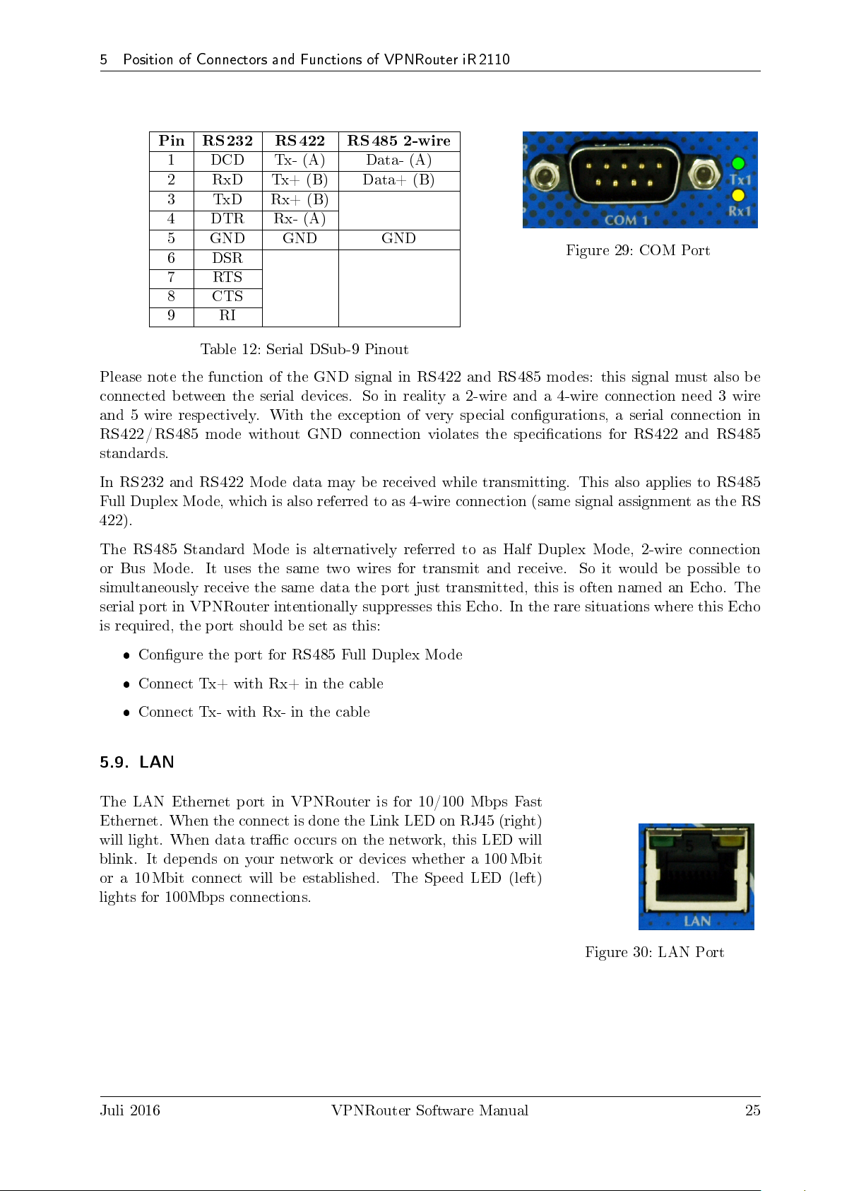
Pin RS232 RS422 RS485 2-wire
1 DCD Tx- (A) Data- (A)
2 RxD Tx+ (B) Data+ (B)
3 TxD Rx+ (B)
4 DTR Rx- (A)
5 GND GND GND
6 DSR
7 RTS
8 CTS
9 RI
Table 12: Serial DSub-9 Pinout
Please note the function of the GND signal in RS422 and RS485 modes: this signal must also be
connected between the serial devices. So in reality a 2-wire and a 4-wire connection need 3 wire
and 5 wire respectively. With the exception of very special congurations, a serial connection in
RS422/RS485 mode without GND connection violates the specications for RS422 and RS485
standards.
Figure 29: COM Port
In RS232 and RS422 Mode data may be received while transmitting. This also applies to RS485
Full Duplex Mode, which is also referred to as 4-wire connection (same signal assignment as the RS
422).
The RS485 Standard Mode is alternatively referred to as Half Duplex Mode, 2-wire connection
or Bus Mode. It uses the same two wires for transmit and receive. So it would be possible to
simultaneously receive the same data the port just transmitted, this is often named an Echo. The
serial port in VPNRouter intentionally suppresses this Echo. In the rare situations where this Echo
is required, the port should be set as this:
Congure the port for RS485 Full Duplex Mode
Connect Tx+ with Rx+ in the cable
Connect Tx- with Rx- in the cable
5.9. LAN
The LAN Ethernet port in VPNRouter is for 10/100 Mbps Fast
Ethernet. When the connect is done the Link LED on RJ45 (right)
will light. When data trac occurs on the network, this LED will
blink. It depends on your network or devices whether a 100 Mbit
or a 10 Mbit connect will be established. The Speed LED (left)
lights for 100Mbps connections.
Figure 30: LAN Port
Juli 2016 VPNRouter Software Manual 25
6 Logon to the Device
5.10. SD-Slot
The VPNRouter provides an SD-Slot on the front side of the case, for cards
in microSD size. The slot supports cards as SD 2.0 or SDHC type, to allow
up to 32 GB of capacity. Class 10 cards are supported as well.
If an operating system is installed on the SD Card, the VPNRouter will boot
this software.
Figure 31: SD Slot
6. Logon to the Device
The Device is congured via an internal web interface. In part this is similar to many SOHO-Routers
on the market. Consequently you need a network connection to the Device, where you then open
your browser to access the web interface. Basically there is one way to get the required access. In
the description here it is assumed the Device is in factory conguration.
6.1. Connect to the Device
6.1.1. Ethernet Cable to LAN Port
That is the option for on-site access, i.e. you are in front of the Device. Plug the Ethernet cable
from your PC into a LAN port (not the WAN port). Your PC uses DHCP to get an IP Address
from the Device. Then open your browser and type the IP Address 192.168.178.1 into the address
bar.
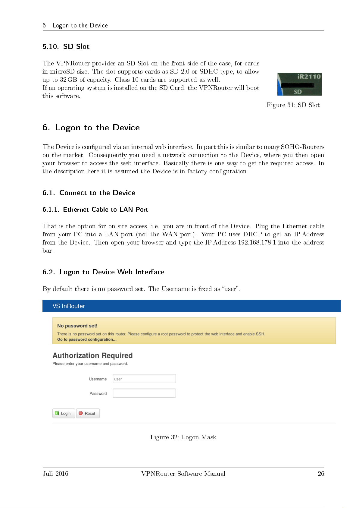
6.2. Logon to Device Web Interface
By default there is no password set. The Username is xed as user.
Figure 32: Logon Mask
Juli 2016 VPNRouter Software Manual 26

6 Logon to the Device
Click on Login to get access to the conguration. On top of the screen is a classic Pull-Down
Menu, but you may also click on the buttons itself. For function of
Logout
this is mandatory.
Figure 33: Pull Down Menu
Note the down-arrow on the buttons
Network,System,Services
and
Logout
. When the mouse
hovers over one of these buttons, the list of menu items opens. Use the mouse to click on one of
the items. There are two views (Administation and Essentials) of the web interface, we only
describe the Essentials view. Use the Administration view if you are experienced and need special
features.
(a) Save and Reset but-
tons
(b) Apply Changes
Figure 34: Save Conguration Changes
The pages use two buttons on the bottom right to apply the parameters, or discard the changes.
Button
a display like gure 34b will appear. The Button
[Save]
will save the new parameters, and apply them automatically. For a short time
[Reset]
will discard any modications in the
conguration forms, back to the last operation of saving or entry to the page.
Juli 2016 VPNRouter Software Manual 27

7 Network
7. Network
Figure 35: Menu Network
The Menu
DHCP.Wi
terface for 3G/UMTS or 4G/LTE communication via mobile com-
munication networks. These two items only appear if the required
interface hardware is available, otherwise they are hidden. A click
on the top button
Network
is for WLAN function and
lists the items of
[Network]
opens the item
General,Wi,3G/4G
3G/4G
congures an in-
General
.
and
Juli 2016 VPNRouter Software Manual 28

7 Network
7.1. General
There are many sections on the web page, explained block by block.
Figure 36: Network General Overview
Save conguration changes using the buttons on the bottom line, see gure 34a on page 27.
Juli 2016 VPNRouter Software Manual 29
7 Network
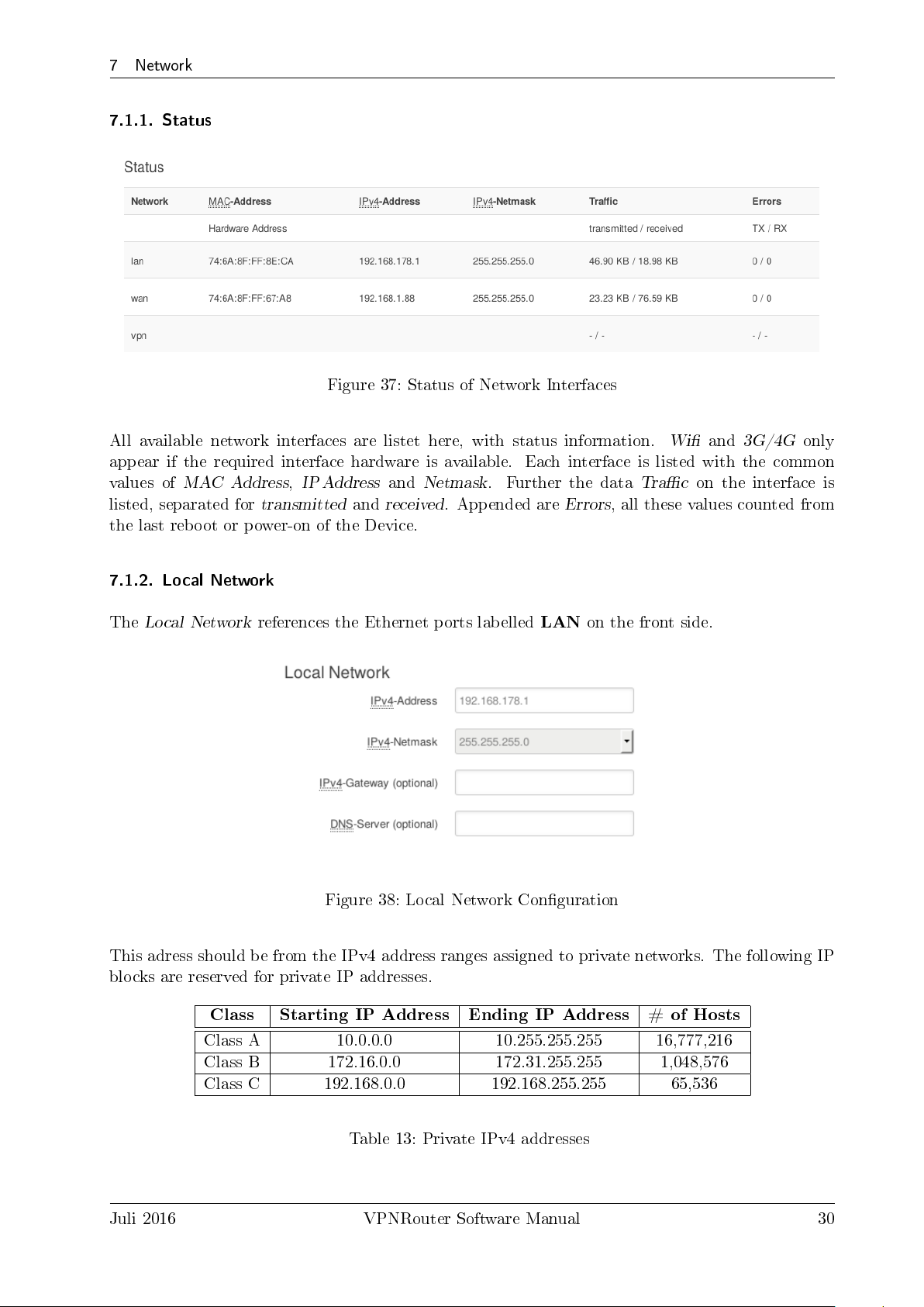
7.1.1. Status
Figure 37: Status of Network Interfaces
All available network interfaces are listet here, with status information.
appear if the required interface hardware is available. Each interface is listed with the common
values of
listed, separated for
the last reboot or power-on of the Device.
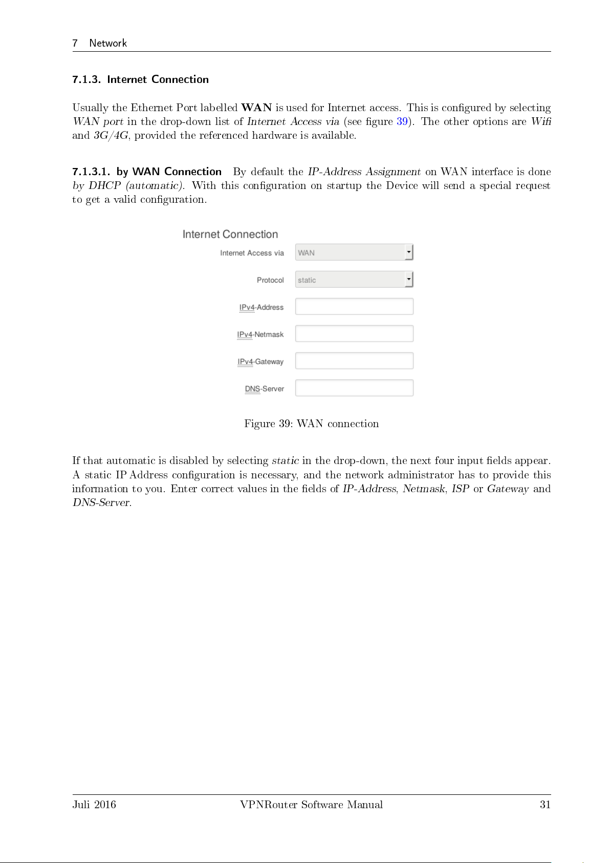
7.1.2. Local Network
The
MAC Address,IP Address
transmitted
Local Network
references the Ethernet ports labelled
and
and
Netmask
received
. Further the data
. Appended are
LAN
Errors
, all these values counted from
on the front side.
Wi
Trac
and
3G/4G
on the interface is
only
Figure 38: Local Network Conguration
This adress should be from the IPv4 address ranges assigned to private networks. The following IP
blocks are reserved for private IP addresses.
Class Starting IP Address Ending IP Address # of Hosts
Class A 10.0.0.0 10.255.255.255 16,777,216
Class B 172.16.0.0 172.31.255.255 1,048,576
Class C 192.168.0.0 192.168.255.255 65,536
Table 13: Private IPv4 addresses
Juli 2016 VPNRouter Software Manual 30
7 Network
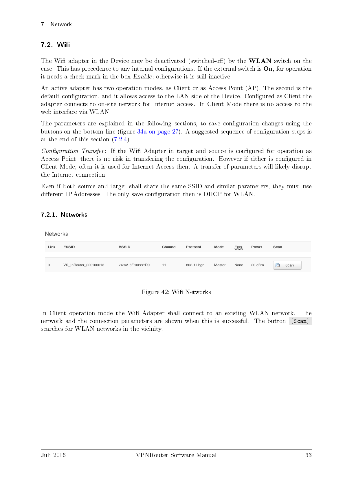
7.1.3. Internet Connection
Usually the Ethernet Port labelled
WAN port
and
3G/4G
7.1.3.1. by WAN Connection
by DHCP (automatic)
to get a valid conguration.
in the drop-down list of
, provided the referenced hardware is available.
. With this conguration on startup the Device will send a special request
WAN
By default the
is used for Internet access. This is congured by selecting
Internet Access via
(see gure 39). The other options are
IP-Address Assignment
Wi
on WAN interface is done
Figure 39: WAN connection
If that automatic is disabled by selecting
A static IP Address conguration is necessary, and the network administrator has to provide this
information to you. Enter correct values in the elds of
DNS-Server
.
static
in the drop-down, the next four input elds appear.
IP-Address,Netmask,ISPorGateway
and
Juli 2016 VPNRouter Software Manual 31

7 Network
7.1.3.2. by 3G/4G Connection
(gure 39), the conguration of the IP Address is done entirely by the provider.
So there is nothing to congure specically, the access parameters are dened in section 7.3 on
page 37.
7.1.3.3. by Wi Connection
this is congured for the Operation Mode as Client (see section 7.2.3 on page 35).
When the Internet access is congured for 3G/4G communication
Figure 40: 3G/4G Conguration
The access to Internet may be done by the WLAN function. Then
Figure 41: Wi Conguration
By default the conguration of the WLAN Client connection is automatic like for the WAN port
(see 7.1.3.1 on the previous page). Then the other parameters are hidden from view. If the eld
Protocol
administrator has to provide this information to you. Enter correct values in the elds of
Netmask,Gateway
Juli 2016 VPNRouter Software Manual 32
has a the value
and
static
, a static IP Address conguration is necessary. Again the network
DNS-Server
IP-Address
.
,
7 Network
7.2. Wi
The Wi adapter in the Device may be deactivated (switched-o) by the
case. This has precedence to any internal congurations. If the external switch isOn, for operation
it needs a check mark in the box
An active adapter has two operation modes, as Client or as Access Point (AP). The second is the
default conguration, and it allows access to the LAN side of the Device. Congured as Client the
adapter connects to on-site network for Internet access. In Client Mode there is no access to the
web interface via WLAN.
The parameters are explained in the following sections, to save conguration changes using the
buttons on the bottom line (gure 34a on page 27). A suggested sequence of conguration steps is
at the end of this section (7.2.4).
Conguration Transfer
Access Point, there is no risk in transfering the conguration. However if either is congured in
Client Mode, often it is used for Internet Access then. A transfer of parameters will likely disrupt
the Internet connection.
Even if both source and target shall share the same SSID and similar parameters, they must use
dierent IP Addresses. The only save conguration then is DHCP for WLAN.
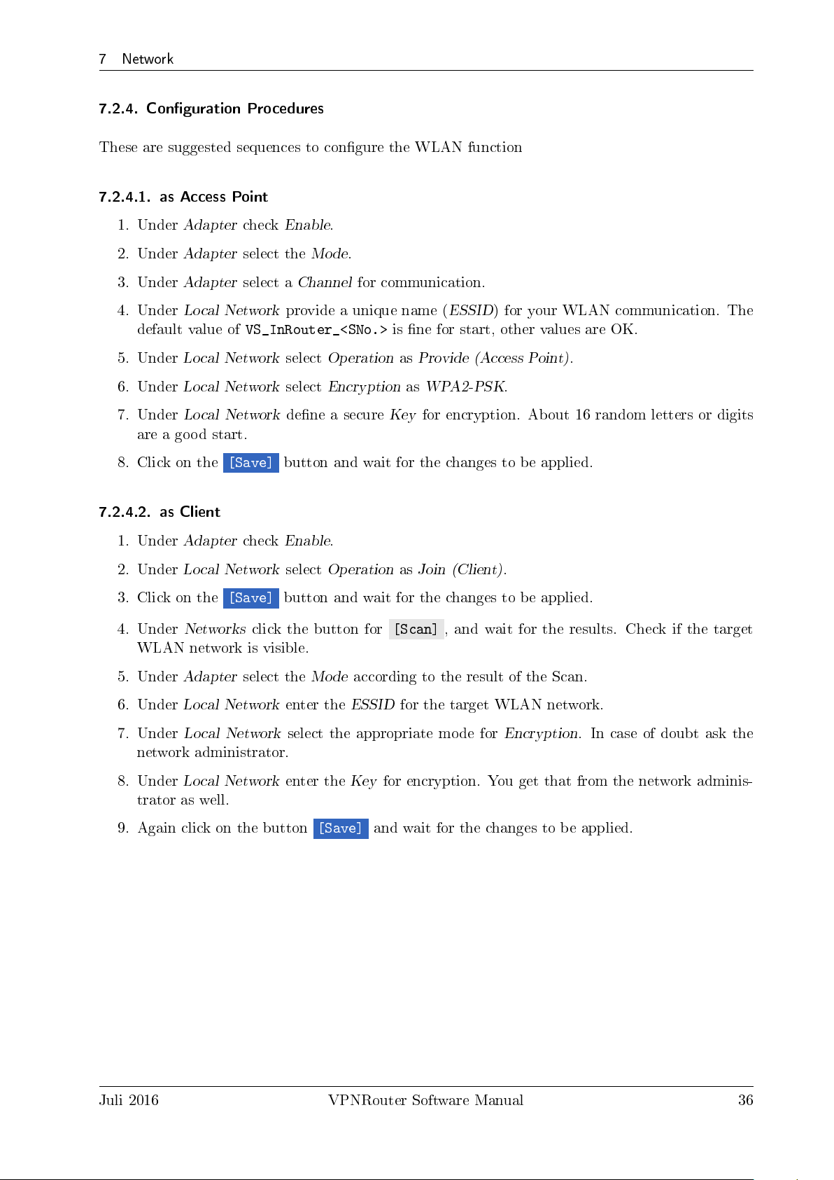
7.2.1. Networks
: If the Wi Adapter in target and source is congured for operation as
Enable
; otherwise it is still inactive.
WLAN
switch on the
Figure 42: Wi Networks
In Client operation mode the Wi Adapter shall connect to an existing WLAN network. The
network and the connection parameters are shown when this is successful. The button
searches for WLAN networks in the vicinity.
Juli 2016 VPNRouter Software Manual 33
[Scan]

7 Network
7.2.1.1. WLAN scanned
connection to the target network.
7.2.2. Adapter
When the Wi
AdapterisEnable
Scanning for WLAN networks may help in select the parameters for a
Figure 43: Wi Scan Results
d, some parameters need selection.
Figure 44: Wi Radio Parameters
The
Mode
Mode choose the value which best matches the conguration provided by the network administra-
tor.
In Client mode you do not need to select the
the Access Point it connects to (gure 43). In AP mode you have to select the channel to operate
on, please check with the network administrator which parameter to use. The selectable values
range from
are forbidden channels, for example in Europe you often are not allowed to use channel 14. The
conguration of
has ve values to select from:
1 (2.4GHz)to14 (2.4GHz)
auto
lets the Adapter search for the best free range.
auto,802.11b,802.11g,802.11a
plus
Channel
auto
. Please also check with local regulations if there
, the Adapter follows the conguration of
and
802.11b+g
. In Client
Juli 2016 VPNRouter Software Manual 34

7 Network
7.2.3. Local Network
Figure 45: Wi Network
These are the nal parameters for WLAN conguration.
WLAN network to connect to. The
Point)
In the eld
ESSID
. The
Encryption
No Encryption
WEP
: This is an old and weak way of security. Only use that in Client Mode, when the
WLAN net does not support better security.
WPA-PSK,WPA2-PSK
encryption. Use this in Access Point Mode, and select a secure Pre-Shared-Key (PSK). WPA2
is the best choice, but WPA is still secure.
WPA-Radius
the Device does not have access to a Radius Server for Authentication.
Key
enter the so-called Passphrase for the Wireless LAN. In combination with the
this denes the PSK for encryption.
mode supports:
: Only use that in Client Mode, when the WLAN net does not support security.
and
and
WPA2-Radius
Operation
WPA-PSK, WPA2-PSK Mixed Mode
: These are usable in Client Mode only, since in AP Mode
mode is either
Network Name (ESSID)
Join (Client)orProvide (Access
: This is state of the art
defnes which
Juli 2016 VPNRouter Software Manual 35
7 Network
7.2.4. Conguration Procedures
These are suggested sequences to congure the WLAN function
7.2.4.1. as Access Point
1. Under
2. Under
3. Under
4. Under
default value of
5. Under
6. Under
7. Under
are a good start.
8. Click on the
7.2.4.2. as Client
1. Under
2. Under
3. Click on the
4. Under
WLAN network is visible.
Adapter
Adapter
Adapter
Local Network
Local Network
Local Network
Local Network
Adapter
Local Network
Networks
check
Enable
select the
select a
provide a unique name (
VS_InRouter_<SNo.>
select
select
dene a secure
[Save]
[Save]
button and wait for the changes to be applied.
check
Enable
select
button and wait for the changes to be applied.
click the button for
.
Mode
Channel
OperationasProvide (Access Point)
EncryptionasWPA2-PSK
.
OperationasJoin (Client)
.
for communication.
ESSID
is ne for start, other values are OK.
Key
for encryption. About 16 random letters or digits
[Scan]
, and wait for the results. Check if the target
) for your WLAN communication. The
.
.
.
5. Under
6. Under
7. Under
network administrator.
8. Under
trator as well.
9. Again click on the button
Adapter
Local Network
Local Network
Local Network
select the
enter the
select the appropriate mode for
enter the
Mode
[Save]
according to the result of the Scan.
ESSID
Key
for the target WLAN network.
Encryption
for encryption. You get that from the network adminis-
and wait for the changes to be applied.
. In case of doubt ask the
Juli 2016 VPNRouter Software Manual 36
7 Network
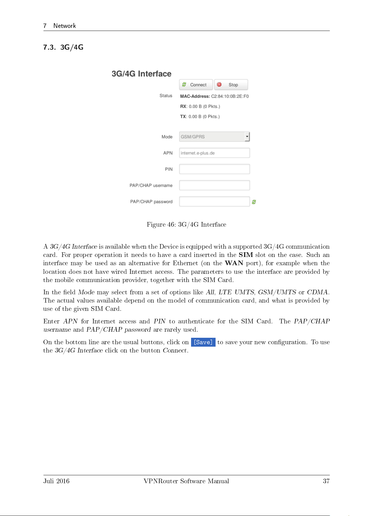
7.3. 3G/4G
Figure 46: 3G/4G Interface
A
3G/4G Interface
card. For proper operation it needs to have a card inserted in the
interface may be used as an alternative for Ethernet (on the
location does not have wired Internet access. The parameters to use the interface are provided by
the mobile communication provider, together with the SIM Card.
In the eld
The actual values available depend on the model of communication card, and what is provided by
use of the given SIM Card.
Enter
username
On the bottom line are the usual buttons, click on
the
3G/4G Interface
Mode
APN
and
is available when the Device is equipped with a supported 3G/4G communication
SIM
slot on the case. Such an
may select from a set of options like
for Internet access and
PAP/CHAP password
click on the button
PIN
are rarely used.
Connect
WAN
All,LTE UMTS,GSM/UMTSorCDMA
to authenticate for the SIM Card. The
[Save]
.
to save your new conguration. To use
port), for example when the
PAP/CHAP
.
Juli 2016 VPNRouter Software Manual 37

7 Network
7.4. DHCP
DHCP is the Dynamic Host Conguration Protocol, the Device has a server component for this
built-in. The protocol is designed to provide correct conguration of IP Address and related pa-
rameters to clients. Clients in this context are any computers/machines/adapters connected to the
LAN
without manually placing parameters into each client.
When the client is started it sends a special request on the network, and it receives an oer from
the server. The server has a range of IP Addresses to choose from. It will attempt to oer the
same IP Address to the client as it did before. If that is not possible for some reason it will oer a
dierent IP Address. An IP Address assigned to a client is named as a Lease in context of DHCP.
The server has a list of known clients, it will identify them by their MAC Address. If the client is on
this list, it gets the pre-dened IP Address reserved for this client as an oer. No other client will
ever get this IPAddress. For clients not on this list on their rst contact to the server they receive
an oer with an IP Address from the range, which does not conict with the IP Addresses of known
clients.
There are some issues to consider with DHCP, see 7.4.4 on page 41.
ports of the Device. The purpose of using DHCP is to have non-conicting congurations
7.4.1. DHCP-Server
Figure 47: DHCP Address Range
The
Start address
addresses are included in the range. The values like
IP Address, the preceeding three numbers are identical to the Device's IP Address (see section 7.1.2
on page 30).
and
End address
dene the available address range for the
100
represent the fourth/last number of an
DHCP-Server
, both
Juli 2016 VPNRouter Software Manual 38

7 Network
7.4.2. Active Leases
Attention!
Figure 48: Active Leases
When a client received an IP Address from the DHCP server, it has a Lease on this address. This
is active for a given time, and the client may request to renew this lease. Clients with a lease are
listed for informational purposes.
To have a
of known clients. Otherwise that eld is just empty. Also listed are
followed by the
7.4.2.1. Automatic Detection of local Devices
uses static IP Address conguration, it will not send a request to the DHCP server. So at rst the
server has no knowledge about that device. But the server monitors certain local network trac,
and will detect static devices when they become active on the network. These are added to the
list of
can't be a name there is a question mark, and the Lease information is
7.4.3. Static Leases
Hostname
Leasetime remaining
Active Leases
appear in the list the client transmits its name, or the client is from the list
IP Address
.
happens under a few restrictions. If a device
for information. Since This page displays many information for reference.there
not DHCP
and
MAC-Address
.
,
Figure 49: Static Leases
The
Static Leases
a new entry in the list, with empty values.
Juli 2016 VPNRouter Software Manual 39
are the methode to congure the list of known clients. The button
[Add]
creates
7 Network
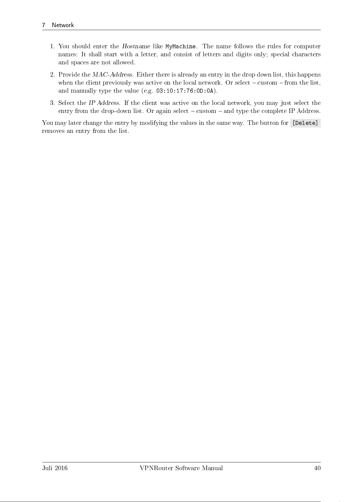
1. You should enter the
names: It shall start with a letter, and consist of letters and digits only; special characters
and spaces are not allowed.
2. Provide the
when the client previously was active on the local network. Or select
and manually type the value (e.g.
3. Select the
entry from the drop-down list. Or again select
You may later change the entry by modifying the values in the same way. The button for
removes an entry from the list.
MAC-Address
IP Address
Hostname
. Either there is already an entry in the drop down list, this happens
. If the client was active on the local network, you may just select the
like
MyMachine
03:10:17:76:0D:0A
. The name follows the rules for computer
custom
custom
).
and type the complete IP Address.
from the list,
[Delete]
Juli 2016 VPNRouter Software Manual 40

8 System
7.4.4. Issues
Startup times: When Device and clients are switched on at the same time, the client may
issue the DHCP request before the DHCP-server in the Device is operating. Then the request
will fail. The client may repeat the request until it gets a sucient oer.
Otherwise the client has to use static IPAddress conguration. Either the IP Address is not
in the Start-to-End range of the server, or better there shall be an entry in the Static Leases
to reserve this address.
Wi: When the Wi adapter is operating in AP mode, connected clients receive their IP Address
conguration from the Device's DHCP-server. In general this is a positive eect.
8. System
Figure 50: Menu System
The Menu
word,Backup/Restore,Flash Firmware
top button
System
[System]
lists the items of
opens the item
General,Language,Admin Pass-
and
Reboot
General
. A click on the
.
Juli 2016 VPNRouter Software Manual 41

8 System
8.1. General
A lot of information is displayed here, but only the
Timezone
is available for conguration.
Figure 51: System General Information
This page displays information for reference. There is the VPNRouter
Hardware Revision
Firmware Version
course.
The
Serial Number
System
Juli 2016 VPNRouter Software Manual 42
Load
, these are xed. The rmware in the Device consists of two components, so the
actually displays two values. With rmware upgrades these values will change of
is printed on the case of the Device. Some statistical parameters like
and usable
Memory
are shown.
Router Model
with its
Uptime
,

8 System
8.2. Language
Figure 52: Select Language
The
Web UI
Deutsch
language your browser uses. In certain congurations this may fail. The other entries do not need
explanation. Save the conguration using the button
(User Interface) supports dierent languages. In the drop-down you may select
and
English
. With
auto
the
Web UI
tries to follow your system conguration, i.e. the
[Save]
as usual.
auto
,
8.3. Admin Password
Figure 53: Set Admin Password
By default there is no password set. On this page you can set a password. Click on the button
[Submit]
against unauthorized access.
and wait for the changes to be applied. A password protects the
Web UI
(User Interface)
8.4. Backup/Restore
The purpose of this functions are given on the web interface. There are some functions on the web
page, explained block by block.
Juli 2016 VPNRouter Software Manual 43

8 System
8.4.1. Download backup
Click
Generate archive
to download a tar archive of the current conguration les.
Figure 54: Backup/Restore
8.4.2. Reset to defaults
Reset this device to factory settings.
may have provided. Also it is possible this operation disconnects the device from the Internet. So
it is recommended to only perform this in person at the device. To discard the conguration in the
Device click on the
8.4.3. Restore backup
To restore conguration les, you can upload a previously generated backup archive.
Perform reset
link.
Attention
: This is not a start conguration your company
8.5. Flash Firmware
Figure 55: Flash Firmware
To ash the rmware upload the new rmware image. The current rmwareimage of the VPNRouter
can be downloaded from ...... . Attention: By default the checkmark is set. Please make sure that
the checkmark in the box is set to keep the current conguration. Otherwise the settings will be
reset to the default conguration when the ash process is done.
Juli 2016 VPNRouter Software Manual 44

8 System
8.6. Reboot
Figure 56: Reboot the Device
In normal circumstances it is not necessary to reboot the Device. If you feel you need to do this,
click on the
Perform reboot
link.
Juli 2016 VPNRouter Software Manual 45
9 Services
9. Services
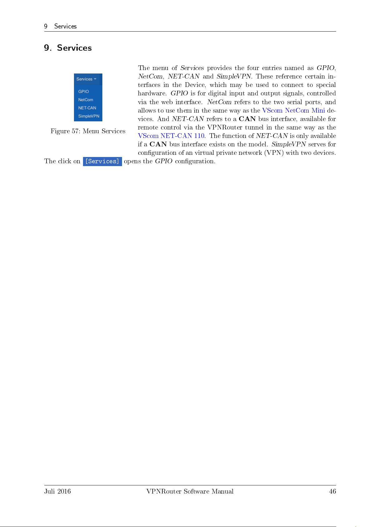
Figure 57: Menu Services
The click on
[Services]
The menu of
NetCom,NET-CAN
terfaces in the Device, which may be used to connect to special
hardware.
via the web interface.
allows to use them in the same way as the VScom NetCom Mini de-
vices. And
remote control via the VPNRouter tunnel in the same way as the
VScom NET-CAN 110. The function of
if a
CAN
conguration of an virtual private network (VPN) with two devices.
opens the
GPIO
Services
GPIO
NET-CAN
bus interface exists on the model.
conguration.
provides the four entries named as
and
SimpleVPN
is for digital input and output signals, controlled
NetCom
refers to a
. These reference certain in-
refers to the two serial ports, and
CAN
bus interface, available for
NET-CAN
is only available
SimpleVPN
GPIO
serves for
,
Juli 2016 VPNRouter Software Manual 46
9 Services
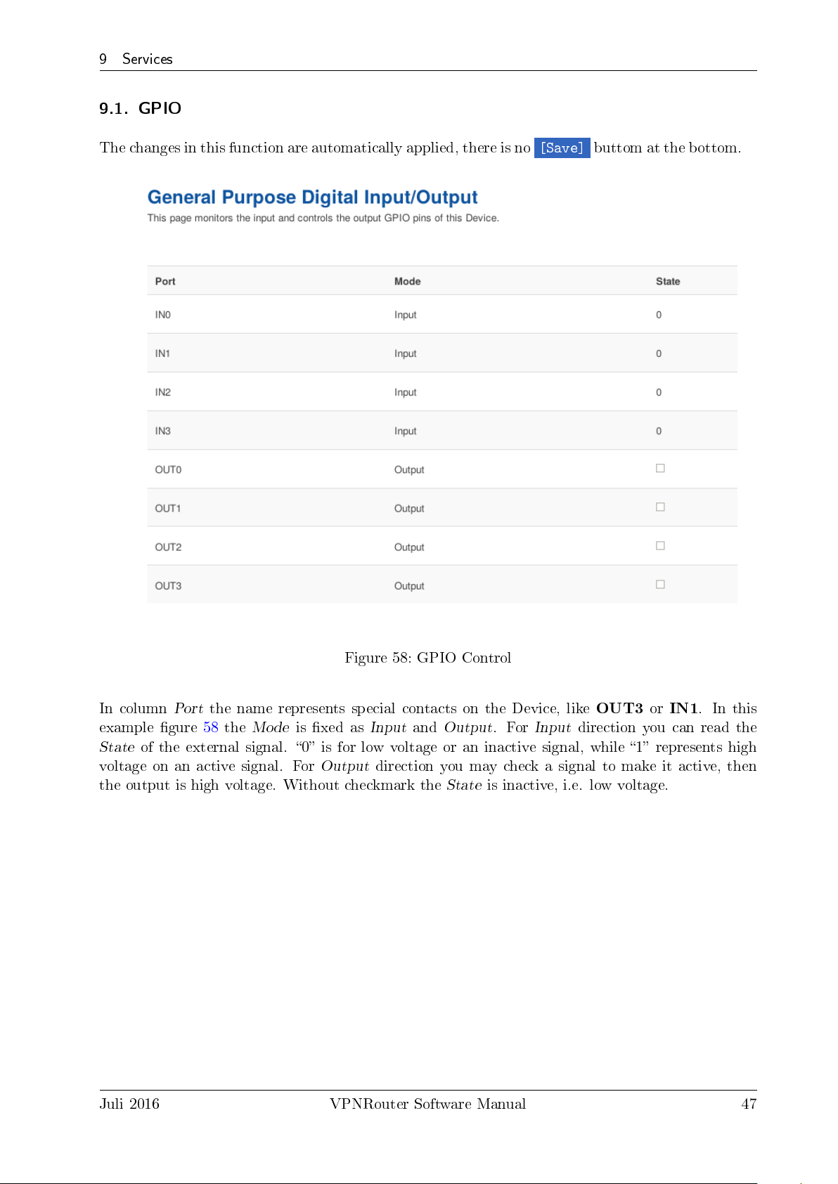
9.1. GPIO
The changes in this function are automatically applied, there is no
[Save]
buttom at the bottom.
Figure 58: GPIO Control
In column
example gure 58 the
State
voltage on an active signal. For
the output is high voltage. Without checkmark the
Port
the name represents special contacts on the Device, like
Mode
of the external signal. 0 is for low voltage or an inactive signal, while 1 represents high
is xed as
Output
Input
and
Output
direction you may check a signal to make it active, then
State
. For
is inactive, i.e. low voltage.
Input
OUT3orIN1
direction you can read the
. In this
Juli 2016 VPNRouter Software Manual 47

9 Services
9.2. NetCom
The Device oers serial ports named as
the protocol known as RFC 2217 is used.
COM1
and
COM2
. For remote control of the serial ports
Figure 59: NetCom Conguration
The upper section
the
COM2
DIP switches are on the underside or back of the device. If the position of the DIP switches is
select by software
supports the modes:
duplex with termination,RS-485 half duplex,RS-485 half duplex with termination,DIP switches
congured mode
The connection for remote control is via TCP/IP, so a
serial port uses
serial ports then operate in the same way as the VScom NetCom Mini Serial Device Servers. There
Juli 2016 VPNRouter Software Manual 48
COM1
port. By default the positions of the DIP switches decisive of the active mode. The
(OFF OFF ON ON) the conguration of the
and
5100
congures operation of serial port
RS-232,RS-422,RS-422 with termination,RS-485 full duplex,RS-485 full
loopback mode
, the next ports use
.
5101
and following (if there are more than two ports). The
COM1
TCP Port
, while section
SW-Mode
is required. By default the rst
COM2
is valid. The
congures
SW-Mode

9 Services
is a driver for Windows operating system, which allows to use the remote serial port like a virtual
local Com Port on your computer. Other drivers or libraries using RFC 2217 are supported in the
same way, and on dierent operating systems.
Figure 60: Conguration RFC2217
The remote control functions are not limited to transmit and receive serial data to a connected
machine. It is also possible to control the status and operation mode of the serial port. The
Protocol
that second choice indeed only transmit and receive with a xed conguration is possible. Let the
Telnet Timeout
extension known as
stay at the value of0.
RFC2217
is used for that purpose, the other choice is
TCP raw
Telnet
. With
Juli 2016 VPNRouter Software Manual 49

9 Services
The following parameters only have an eect when
are fairly common and do not need much explanation.
TCP raw
is selected for communication. They
Figure 61: Conguration TCP raw
The
Baudrate
of
custom
The
DataBit
The
Parity
The
StopBit
Finally the
RTS/CTS
Activate the new conguration using the
is selectable from a drop-down list of common values. At the bottom the entry
let you type the desired rate into the box (e.g.
s are possible as8or7.
is available with the choice of
may have a duration of1or2data bits.
FlowType
(hardware handshake).
is usable as
None
[Save]
None,Even
(no control),
button.
31250
and
Odd
.
XON/XOFF
).
(software ow control) and
Juli 2016 VPNRouter Software Manual 50

9 Services
9.3. NET-CAN
Some models also support an interface to
TCP/IP, from remote locations and the LAN ports. It supports the same VSCAN library as the
VScom NET-CAN CAN Gateways.
Figure 62: NET-CAN Conguration
The conguration for remote control just requires to dene the network parameters. Here only the
TCP Port
is necessary, the default value is
CAN
5030
Bus. This interface is usable via network by
.
Juli 2016 VPNRouter Software Manual 51

9 Services
9.4. SimpleVPN
The service SimpleVPN allows easy conguration of an virtual private network (VPN) connecting
two or more locations with an encrypted tunnel. This service can congure a pair or more industrial
routers; so that all routers have a functional conguration after this dialog. Note: The service
SimpleVPN is only important if you have a set of industrial routers. There are several options on
this web page that will be explained block by block. You can make all relevant settings which are
needed for a virtual private network (VPN) on this page.
Figure 63: Overview SimpleVPN
Juli 2016 VPNRouter Software Manual 52
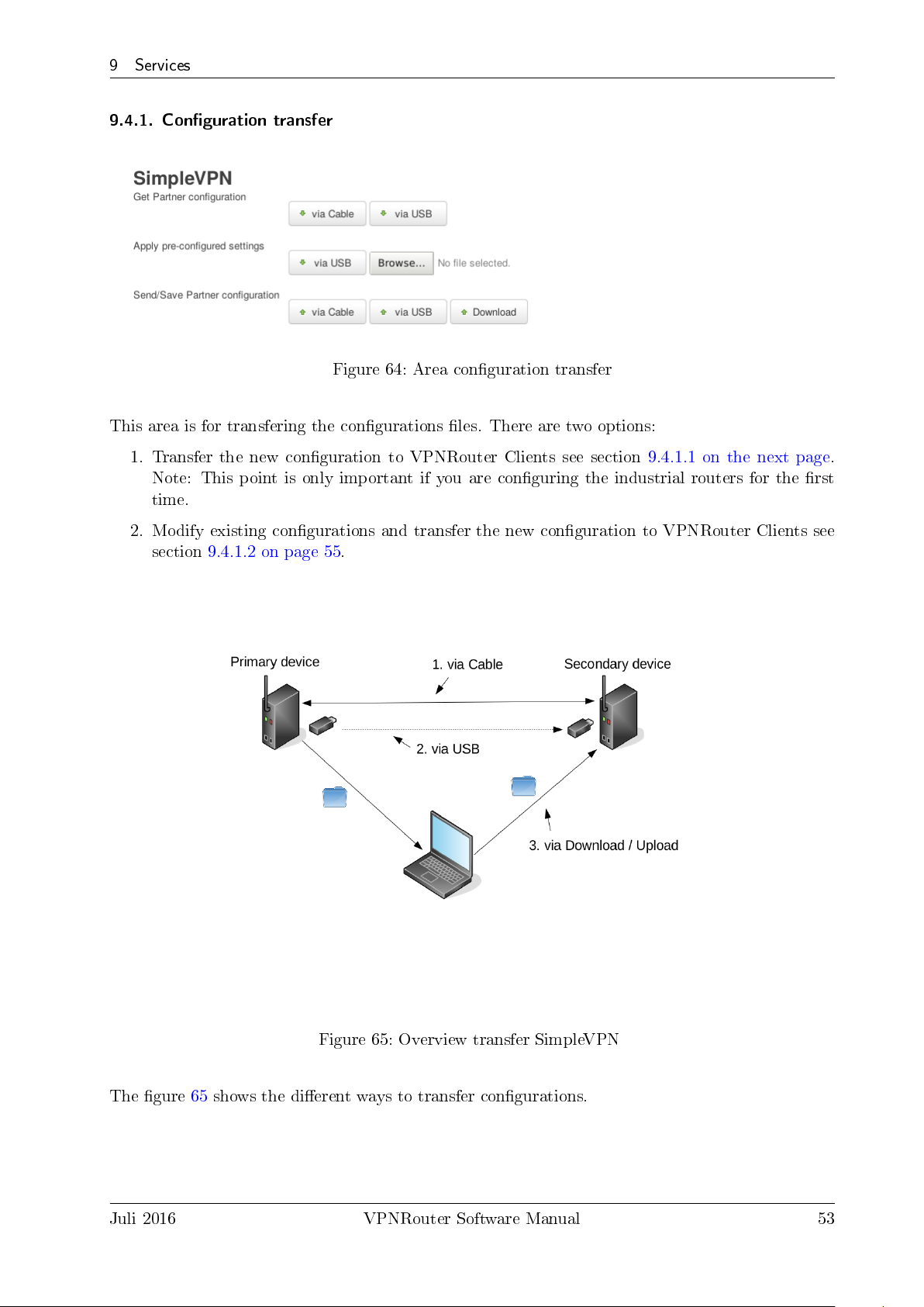
9 Services
9.4.1. Conguration transfer
Figure 64: Area conguration transfer
This area is for transfering the congurations les. There are two options:
1. Transfer the new conguration to VPNRouter Clients see section 9.4.1.1 on the next page.
Note: This point is only important if you are conguring the industrial routers for the rst
time.
2. Modify existing congurations and transfer the new conguration to VPNRouter Clients see
section 9.4.1.2 on page 55.
Figure 65: Overview transfer SimpleVPN
The gure 65 shows the dierent ways to transfer congurations.
Juli 2016 VPNRouter Software Manual 53

9 Services
9.4.1.1. New conguration
There are three dierent options to send the new conguration to a other device.
1.
via Cable
corresponds to point 1 of gure 65 on the preceding page.
:
a) Make sure that the devices are connected together via the
needed to connect all Clients.
b) Check that the conguration is correct and certicates and keys are present.
c) To send the conguration to the partner device use the button
Send/Save Partner conguration.
d) A list of all connected VPNRouters is presented.
e) Choose a VPNRouter by clicking on it. The SimpleVPN page is shown (after authentica-
tion if a password was already set). The APP LED will also light to show which Router
you are conguring.
f) Please choose a Client. Use the button
The button
g) Continue with the remaining Routers at e).
2.
via USB
corresponds to point 2 of gure 65 on the previous page.
a) Make sure that the USB stick is connected to the USB port on the device.
b) Check that the conguration is correct and certicates and keys are present.
:
[Selected]
will be displayed in green.
[Selected]
LAN port
to apply the Client congurations.
. A switch may be
[via Cable]
in the area
c) When you use the button
new folder will be created on the USB Stick with congurations, certicates and keys in
it.
d) Disconnect the USB stick from the USB port.
e) Disconnect the device from the LAN port.
f) Connect a VPNRouter Client to your PC via the LAN port with an Ethernet cable.
g) Connect the USB stick to the Router.
h) Then open your browser and type the IP Address 192.168.178.1 into the address bar.
i) Logon the Web UI (Webinterface) see section 6.2 on page 26.
j) Open the SimpleVPN site.
k) To apply the conguration for the Client use the button
pre-congured settings.
l) Please choose the corresponding Client. Use the button
congurations. The button
m) Disconnect the USB stick from the USB port.
[via USB]
[Selected]
in the area Send/Save Partner conguration a
[via USB]
[Selected]
will be displayed in green.
in the area Apply
to apply the Client
Juli 2016 VPNRouter Software Manual 54

9 Services
n) Continue with the remaining Routers at e).
3.
via Download / Upload
corresponds to point 1 of gure 65 on page 53.
:
a) Use the button
b) Now you can save the tgz le on your own computer.
c) Disconnect the Server from the LAN port.
d) Connect a Client to your PC via the LAN port with an Ethernet cable.
e) Then open your browser and type the IP Address 192.168.178.1 into the address bar.
f) Logon the Web UI (Webinterface) see section 6.2 on page 26.
g) Open the SimpleVPN site.
h) You can upload the generated tgz le in the area Apply pre-congured settings to apply
the conguration to the secondary device. Click on
your computer.
i) Please choose the corresponding Client. Use the button
congurations. The button
j) Continue with the remaining Routers at e).
9.4.1.2. Existing congurations
Attention: Changes in the exsiting VPN network should only be made if it is necessary. There
are two options to modify existing congurations.
[Download]
to generate a tgz le.
[Selected]
will be displayed in green.
[Browse]
[Selected]
and select the tgz le from
to apply the Client
1.
via Cable
a) Make sure that the devices are connected together via the
b) Using the button
c) Now you can modify the conguration.
d) When the necessary settings have been made, click on the button
e) Transfer the conguration see in section 1 on the previous page.
2.
via USB
a) Check that the conguration is available on your USB stick. It is the folder VS-Router
b) Connect the USB stick with the USB port on the device.
c) Using the button
d) Now you can modify the conguration.
:
[via Cable]
guration from the secondary device .
wait for the changes to be applied.
:
with congurations, certicates and keys les.
[via USB]
uration from the secondary device.
in the area Get Partner conguration to get the con-
in the area Get Partner conguration to get the cong-
LAN port
[Save & Apply]
.
and
Juli 2016 VPNRouter Software Manual 55
9 Services
e) When the necessary settings hnd cannot be used. The following table shows the gener-
f) Transfer the conguration see section 2 on page 54.
alave been made, click on the button
applied.
[Save & Apply]
and wait for the changes to be
Juli 2016 VPNRouter Software Manual 56

9 Services
9.4.2. Conguration
In this section you can make all relevant settings which are needed for a virtual private network
(VPN). If all settings are correct and complete click on the button
the changes to be applied. The goal of this service is to build a virtual private network (VPN)
to connect two or more locations with an encrypted tunnel. The advantage of a VPN is that it
expands an existing network over the Internet while ensuring to transmit sensitive data in a way
that protects it from tampering and interception. This service helps to make the necessary settings
step by step. The current device is automatically the
The gure 66 shows an exemplary topology.
Server
. It allows to congure multiple devices.
[Save & Apply]
and wait for
Figure 66: Topology
Juli 2016 VPNRouter Software Manual 57

9 Services
9.4.2.1. Server Settings
9.4.2.1.1. Public Server IPv4 Adress or Domain Name
IPv4 Adress
or the
Domain Name
In this section you can make the necessary settings for the
Please ll in this eld the
.
Server
.
Public Server
Figure 67: SimpleVPN- Public Server IPv4 Address
The must be the public IP address under which the
Server
VPNRouter is or will be accessible
over the Internet. You may use services like https://www.whatismyip.com/. The Internet Service
Provider may (preferibly) assign a static IP address to your Internet access. If only a dynamic IP
address is available, a DynDNS service is necessary. The resulting DNS name belongs in this eld
in that case. To make the Router accessible you may need to do a few more steps explained in the
following section.
9.4.2.1.2. Server Mode and Client Mode
tion. You can use the device as
Internet RouterorVPN Gateway
It is possible to use the devices in two dierent varia-
.
(a) Server Mode (b) Client Mode
Figure 68: Server and Client Mode
Dierence between
Internet Router
Provides its own network on LAN-Ports with DHCP Server
Provides the rewall to protect the local network
Provides access to the other site over an encrypted VPN tunnel
All device on the LAN side have access to the VPN.
The WAN-Port is directly (or possibly indirectly behind a modem) attached to the Internet.
Internet Router
:
and
VPN Gateway
.
Juli 2016 VPNRouter Software Manual 58

9 Services
Figure 69: Internet Router
Juli 2016 VPNRouter Software Manual 59
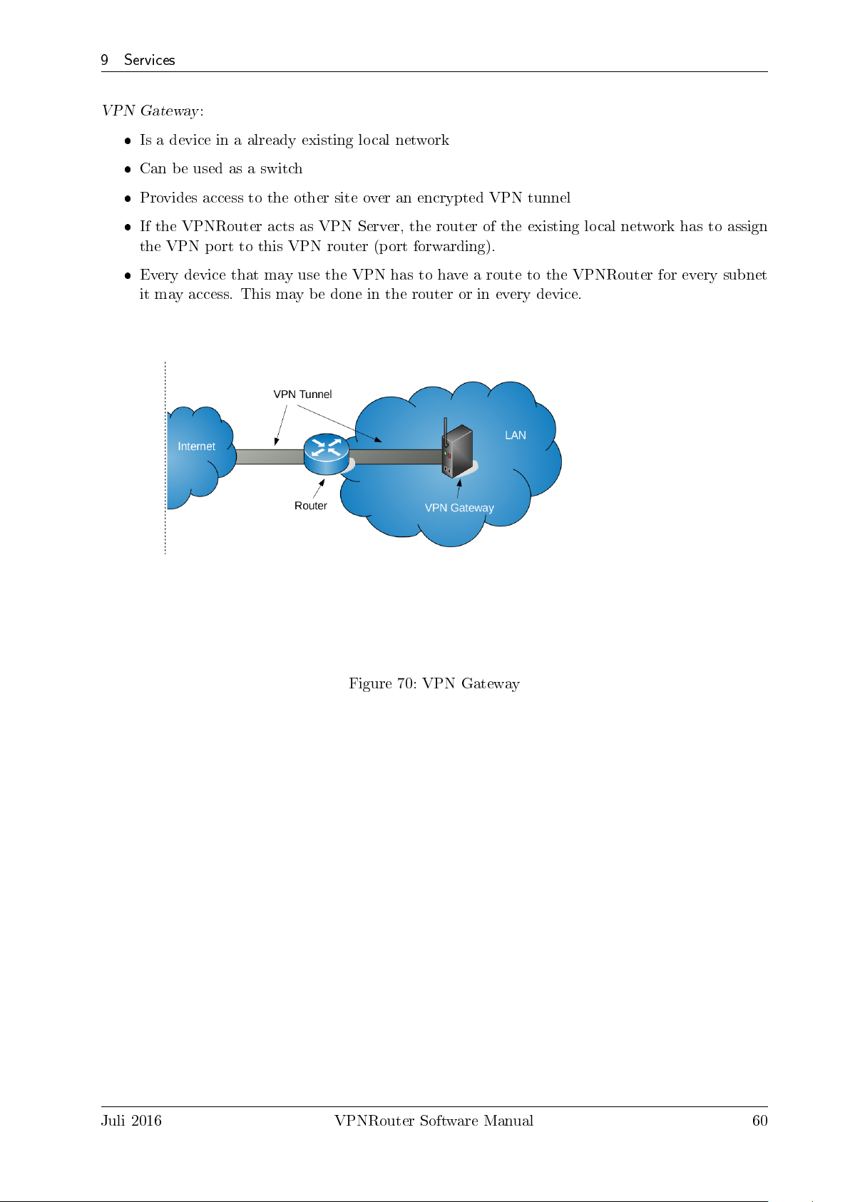
9 Services
VPN Gateway
Is a device in a already existing local network
Can be used as a switch
Provides access to the other site over an encrypted VPN tunnel
If the VPNRouter acts as VPN Server, the router of the existing local network has to assign
the VPN port to this VPN router (port forwarding).
Every device that may use the VPN has to have a route to the VPNRouter for every subnet
it may access. This may be done in the router or in every device.
:
Figure 70: VPN Gateway
Juli 2016 VPNRouter Software Manual 60
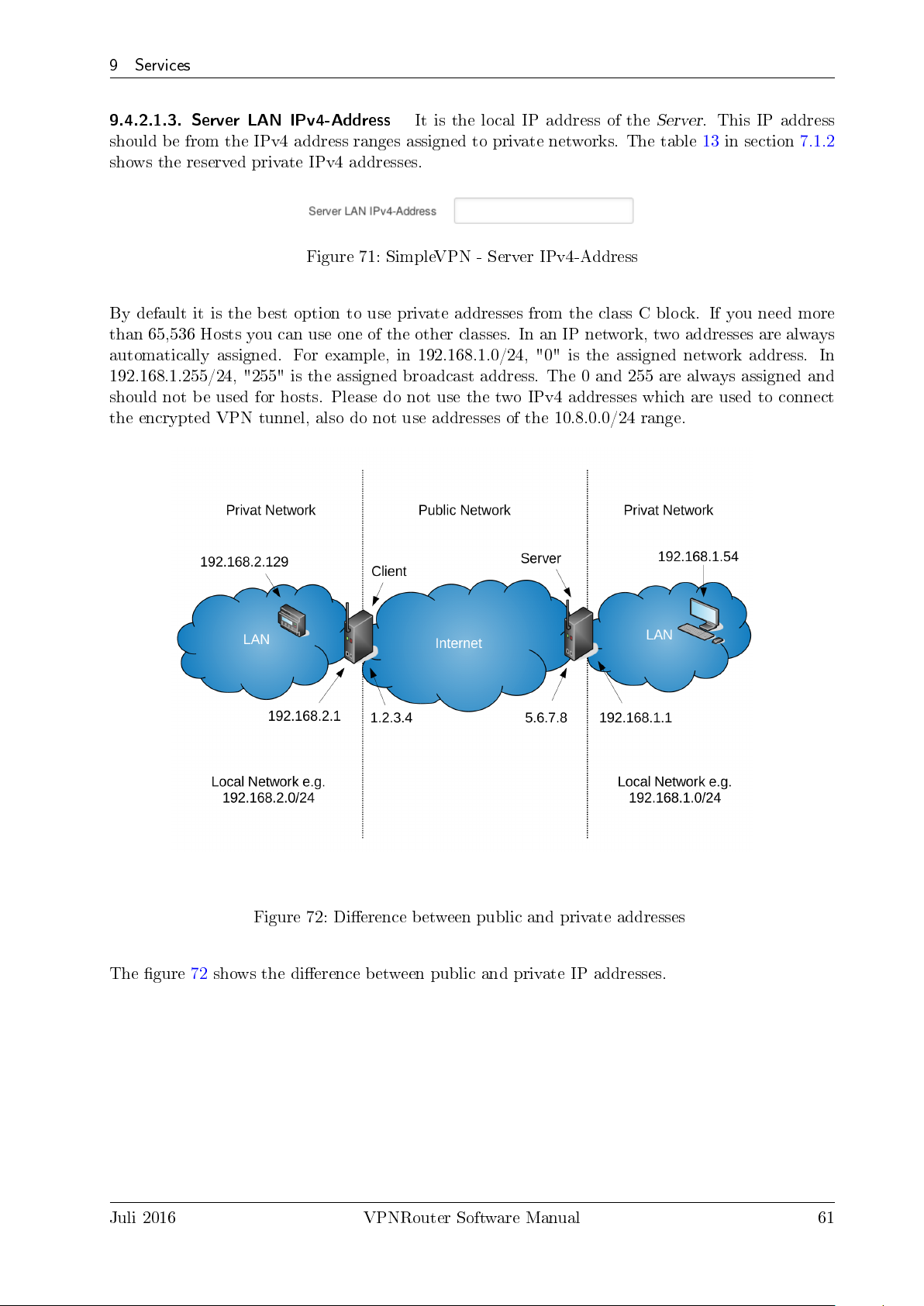
9 Services
9.4.2.1.3. Server LAN IPv4-Address
should be from the IPv4 address ranges assigned to private networks. The table 13 in section 7.1.2
shows the reserved private IPv4 addresses.
Figure 71: SimpleVPN - Server IPv4-Address
By default it is the best option to use private addresses from the class C block. If you need more
than 65,536 Hosts you can use one of the other classes. In an IP network, two addresses are always
automatically assigned. For example, in 192.168.1.0/24, "0" is the assigned network address. In
192.168.1.255/24, "255" is the assigned broadcast address. The 0 and 255 are always assigned and
should not be used for hosts. Please do not use the two IPv4 addresses which are used to connect
the encrypted VPN tunnel, also do not use addresses of the 10.8.0.0/24 range.
It is the local IP address of the
Server
. This IP address
Figure 72: Dierence between public and private addresses
The gure 72 shows the dierence between public and private IP addresses.
Juli 2016 VPNRouter Software Manual 61

9 Services
9.4.2.1.4. Server LAN Netmask
address. A netmask is a 32-bit mask used to divide an IP address into subnets and specify the
networks available hosts.
Figure 73: SimpleVPN - Server LAN Netmask
The following table shows common netmasks
Class Netmask length # of networks # of hosts Netmask
Class A 8 126 16,777,214 255.0.0.0
Class B 16 16,382 65,534 255.255.0.0
Class C 24 2,097,150 254 255.255.255.0
9.4.2.1.5. Transport Protocol
transport protocol UDP is selected.
Please choose the corresponding netmask for the private IPv4
Table 14: Common netmasks
It is possible to change the transport protocol. By default the
Figure 74: SimpleVPN - Transport Protocol
TCP is a connection oriented stream over an IP network. It guarantees that all sent packets will
reach the destination in the correct order. This imply the use of acknowledgement packets sent back
to the sender, and automatic retransmission, causing additional delays and a general less ecient
transmission than UDP. UDP is a connection-less protocol. Communication is datagram oriented.
The integrity is guaranteed only on the single datagram. Datagrams reach destination and can
arrive out of order or don't arrive at all. It is more ecient than TCP because it does not use
ACKs. It's generally used for real time communication, where a little percentage of packet loss rate
is preferable to the overhead of a TCP connection.
Juli 2016 VPNRouter Software Manual 62
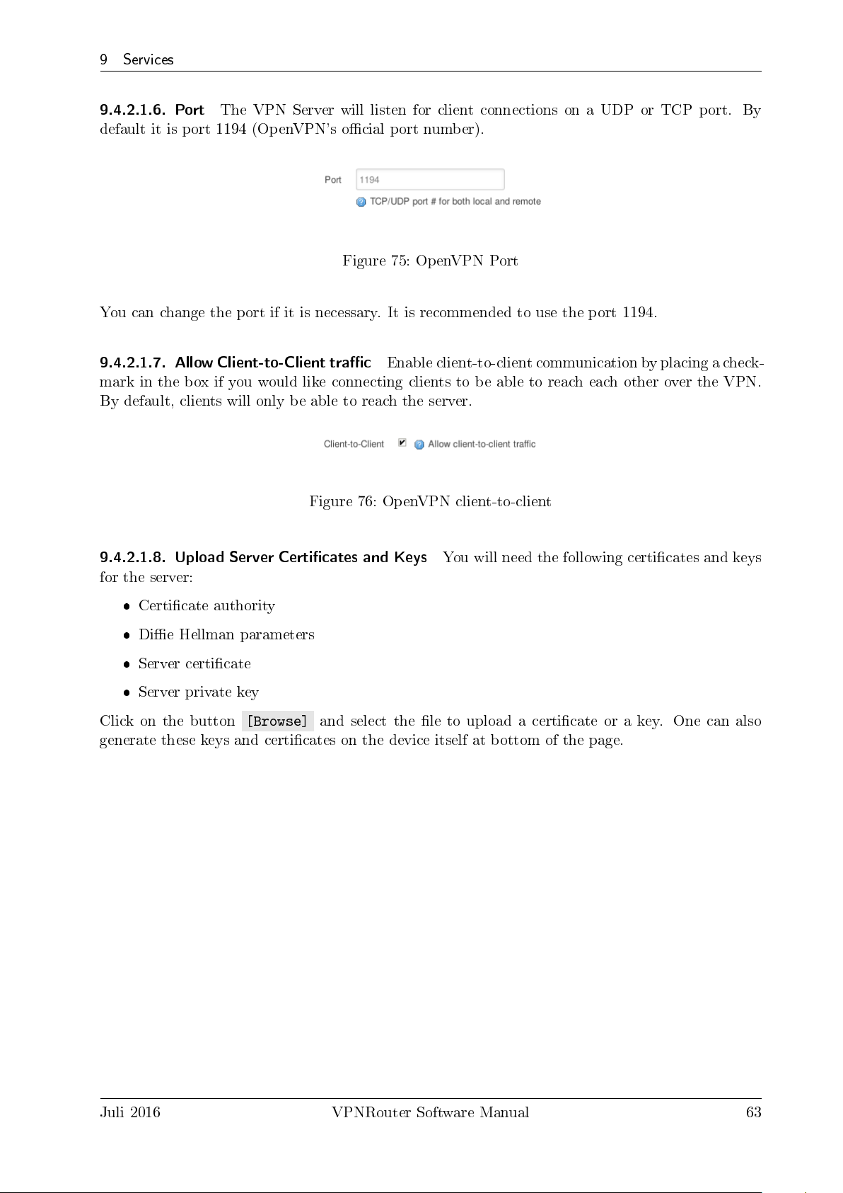
9 Services
9.4.2.1.6. Port
default it is port 1194 (OpenVPN's ocial port number).
You can change the port if it is necessary. It is recommended to use the port 1194.
9.4.2.1.7. Allow Client-to-Client trac
mark in the box if you would like connecting clients to be able to reach each other over the VPN.
By default, clients will only be able to reach the server.
The VPN Server will listen for client connections on a UDP or TCP port. By
Figure 75: OpenVPN Port
Enable client-to-client communication by placing a check-
Figure 76: OpenVPN client-to-client
9.4.2.1.8. Upload Server Certicates and Keys
for the server:
Certicate authority
Die Hellman parameters
Server certicate
Server private key
Click on the button
generate these keys and certicates on the device itself at bottom of the page.
[Browse]
and select the le to upload a certicate or a key. One can also
You will need the following certicates and keys
Juli 2016 VPNRouter Software Manual 63

9 Services
9.4.2.2. Add a Client
Client_1
It appears an area where you can congure the
. To add the client please click on the button
Please enter the name of the client in the appropriate eld. For example
Figure 77: Add a Client
[Add]
Client
. See section 9.4.2.3.
.
Figure 78: Client overview
Juli 2016 VPNRouter Software Manual 64

9 Services
9.4.2.3. Client Settings
9.4.2.3.1. Client LAN IPv4-Address
should be from the IPv4 address ranges assigned to private networks. The table 13 on section 7.1.2
shows the reserved private IPv4 addresses.
By default it is the best option to use private adresses from the class C block. If you need more
than 65,536 Hosts you can use one of the other classes. Please use not the two IPv4 addresses which
are used to connect the encrypted VPN tunnel, also do not use addresses of the 10.8.0.0/24 range.
The gure 72 shows the dierence between public and private IP addresses.
9.4.2.3.2. Client LAN IPv4-Netmask
IPv4 address. A netmask is a 32-bit mask used to divide an IP address into subnets and specify
the networks available hosts.
In this section you can make the necessary settings for each
It is the local network IP address of the
Figure 79: SimpleVPN - Client LAN IPv4-Address
Please choose the corresponding netmask for the private
Client
Client
.
. This adress
Figure 80: SimpleVPN - Client LAN Netmask
The table 14 in section 9.4.2.1.4 shows common netmasks.
9.4.2.3.3. Upload Client Certicates and Keys
for each client:
Client certicate
Client private key
Click on the button
generate these keys and certicates on the device itself at bottom of the page.
[Browse]
and select the le to upload a certicate or a key. One can also
You will need the following certicates and keys
Juli 2016 VPNRouter Software Manual 65

9 Services
9.4.2.4. Delete a Client
the virtual private network (VPN). Use the button
client.
It is possible to delete a created client. The client will be removed from
[Delete]
on the right side to remove a created
Figure 81: Client delete
Juli 2016 VPNRouter Software Manual 66

9 Services
9.4.3. Generate Certicates and Keys
You have the option to generate new certicates and keys on the VPNRouter. The generation
process is very simple.
Figure 82: Generate Certicates and Keys
Please ll in all necessary elds. Click the button
[Generate]
If you click on the button
in the background. A set of DieHellman parameters are already on the Router because the
generation process on the device may take a considerable time. They will become visible after
the generation the other keys and certicates. Use the button
calculate and get new DieHellman parameters. After the generation process the certicates and
keys will be displayed as if they were uploaded. You may need to reload the page.
and
[Generate DH Parameters]
Figure 83: Buttons Generate and Generate DH Parameters
[Generate]
the certicates and keys will automatically be generated
[Save]
will be displayed.
. After the store process the button
[Generate DH Parameters]
to
Juli 2016 VPNRouter Software Manual 67
B License
A. History
Juli 2016
Release Manual
B. License
Figure 66, 69, 70, 65, 72 build upon VRT Network Equipment (Shape Gallery for LibreOce/OpenOce)
by VRT Systems licensed under CC BY-SA 3.0 .
Juli 2016 VPNRouter Software Manual 68
 Loading...