

Page 1
VisionStat®
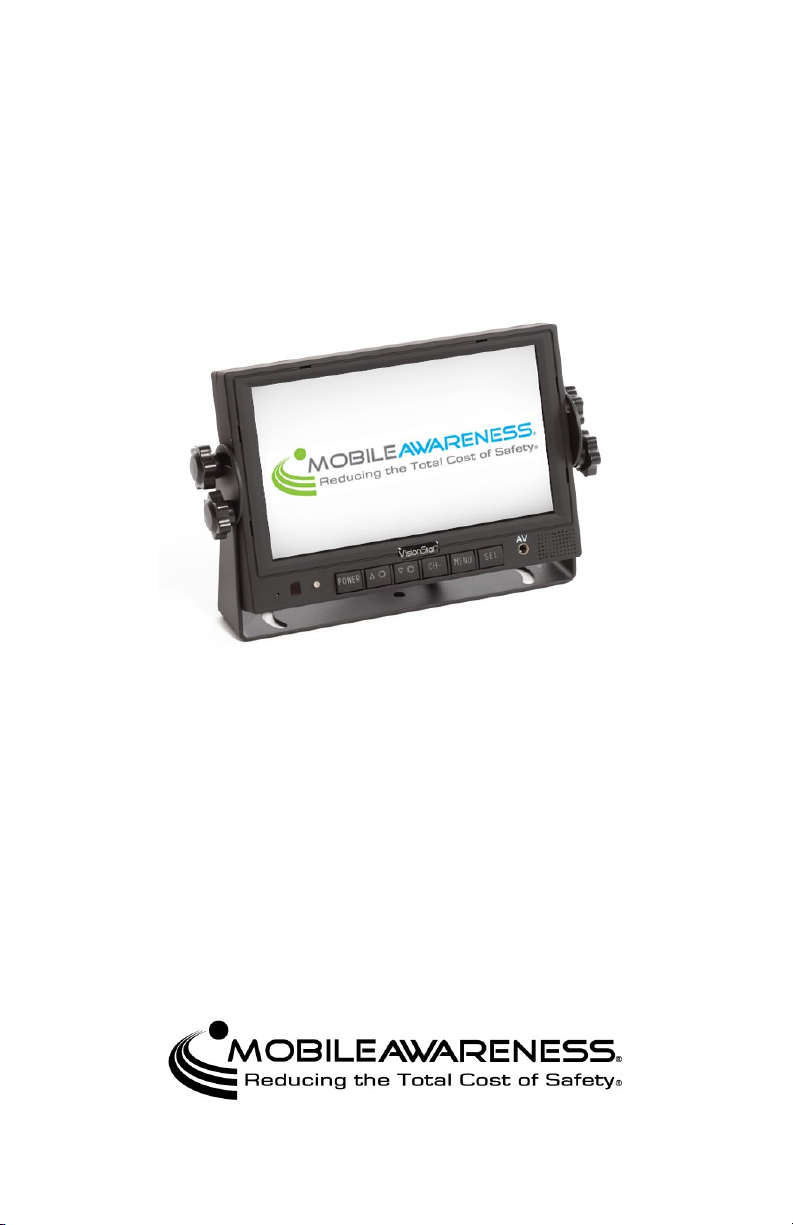
5.6” and 7.0” Wired Video Monitoring Systems
MA-BCKS-5.6 Models
MA-BCKS-7.0 Models
Installation & User Manual
Please read this manual thoroughly before operating the device
and keep this document for future reference
www.mobileawareness.com
Page 2

Mobile Awareness
Mobile Awareness, LLC VisionStat® Manufacturer’s Limited Warranty
1-Year Limited Warranty
(Revised 6/2010)
Limited Warranty
VisionStat™Limited Warranty Mobile Awareness warrants to the original end-user purchaser that
a new VisionStat™ Color Camera System is free from structural defects in material and
workmanship and agrees, without charge, to repair or replace any part(s) which fails in normal use
and service because of structural defects in material and workmanship. The VisionStat™ system is
warranted to the original end-user purchaser for (1) one year from the date of purchase. Proof of
original ownership shall be evidenced by invoice or bill of sale in the name of the original end -user
purchaser. This warranty is not transferable. Warranty Limitations: Mobile Awareness does not
warrant and will not repair or replace or make adjustment with respect to any VisionStat™ system
that has been subjected to misuse or abuse, including the following: a) Not following the guidelines
expressed in the Installation Guide ; b) Intentional mis-use or mis-application; c) Changing the
original condition of the VisionStat™ system by alteration or by subjecting it to any processing such
as welding or straightening; e) Accidents, abnormal or severe operating conditions including,
without limitation, fires, or driving during seizures or with a flat tire; f) Failing to follow maintenance
and other instructions and warnings periodically set forth by Mobile Awareness, Recommended
maintenance includes, without limitation, periodic cleaning and inspection for damage; g) This
warranty is void if the original invoice or sales receipt is not available for verification, or upon
transfer of title on any products by the original purchaser. THERE IS NO WARRANTY THAT THE
VisionStat™ SYSTEM SHALL BE MERCHANTABLE OR SATISFACTORY FOR ANY
PARTICULAR PURPOSE. NOR IS THERE ANY OTHER WARRANTY, EXPRESS OR IMPLIED,
EXCEPT SUCH AS IS EXPRESSLY SET FORTH HEREIN. MOBILE AWARENESS, LLC SHALL
NOT BE LIABLE FOR ANY INCIDENTAL OR CONSEQUENTIAL DAMAGES FOR ANY BREACH
OF W ARRANTY, ITS LIABILITY AND THE PURCHASER’S EXCLUSIVE REMEDY BEING
LIMITED TO REPAIR OR REPLACEMENT OF THE VisionStat™ SYSTEM AS STATED IN THIS
LIMITED W ARRANTY. Please refer to Mobile Awareness standard Terms and Conditions.
Customer must notify Mobile Awareness within 10 days of discovering the defective product or part
and provide a description of the defect and complete information about the manner of its discovery.
Repair or replacement will be handled by a Mobile Awareness representative. This warranty gives
you specific legal rights. You may have additional rights covered under applicable laws.
This limited warranty should be used in conjunction with the VisionStat™ Installation Manual
(“Installation Manual”). The Installation Manual contains important safety information and warnings,
and failure to read and understand this information may result in serious injury or death. If you do
not have copies of the Installation Manual you may obtain copies free of charge along with other
specification literature by contacting Mobile Awareness at (866) 653-5036 or the address below:
Mobile Awareness, LLC
31200 Solon Road, Suite 12
Solon, OH 44139
www.mobileawareness.com
Limitation of Liability.
(a) Seller’s liability and Buyer’s exclusive remedy f or any tender of nonconforming or defective
goods or breach of warranty is expressly limited to Seller’s choice of: (i) the repair of non-
conforming or defective goods; (ii) the replacement of non-conforming or defective goods with
conforming goods at the FOB point of shipment; or (iii) the repayment of that portion of the
purchase price represented by non-conforming or defective goods.
(b) In no event will Seller be liable for any incidental, consequential, indirect, special, contingent, or
punitive damages arising out of or relating to: (i) any breach of contract or warranty, tort (including
negligence and strict liability), or other theories of law with respect to products sold or s ervices
rendered by Seller, or undertakings, acts or omissions relating thereto; (ii) the tender of defective
or non-conforming goods; (iii) breach of any other provision of this agreement; or (iv) any claim of
any kind arising out of or relating to any order or Seller’s performance in connection therewith. In
any event, Seller’s liability will not exceed the purchase price of the goods on which such liability is
based. Buyer assumes all other liability for any loss, damage or injury to persons or property
arising out of, connected with or resulting from the use of Seller’s products, either alone or in
combination with other products.
2
Page 3

VisionStat 5.6” and 7.0” Wired Video Monitoring Systems
Contents of Manual
1. Product Overview, Product Features, Product Specifications………………..….…..5
2. VisionStat Package Contents, Optional Items and Accessories........………............6
3. About the Monitor.....................................................................................................6
4. About the Cameras...............................................................................................…7
5. Installation: Monitor and Wiring Harness..................................................................7
6. Installation: Cameras................................................................................................9
7. Menus.....................................................................................................................11
8. Maintenance & Troubleshooting.............................................................................12
9. Backing Safety Suggestions...................................................................................13
Precautions
GENERAL SAFETY INFORMATION
All Mobile Awareness, LLC products are strictly intended to be installed as a supplement and are not intended for use as substitutes for vehicle side/rear-view mirror de-
vices, or for any other standard motor vehicle equipment required to be installed on
vehicles by law. Objects in Camera/Monitor view are closer than they appear. When
backing up, proceed cautiously and be prepared to stop. This product is no substitute
for proper attention and defensive driving techniques, observances of traffic laws and
motor vehicle safety regulations.
WARNING
It is unlawful in most jurisdictions for any person(s) to drive a motor vehicle equipped
with a television viewer/screen located at any point forward of the back of the driver’s
seat (or in any location that is visible, directly or indirectly), to the driver while operating
the vehicle. In any installations where such products are used to display television
broadcasts or recorded video playback, installation location must adhere to applicable
laws and regulations.
TAMPERING
To prevent electrical shock, DO NOT OPEN THE MONITOR CASE OR ANY OTHER
ENCLOSED ELECTRONIC PRODUCT. There may be potentially harmful voltages
inside these enclosed products. There is no user serviceable parts inside any of the
products provided by Mobile Awareness, LLC. If tampering is detected, the warranty
will become void.
CAUTION
To avoid damage to electronic circuit, stop using this product while doing welding work
to the vehicle and/or trailers. Never immerse any component in water and do not em-
ploy spray cleaners. When cleaning, use a damp lint-free cloth only. Never connect
this unit to other devices that may be incompatible as it may void the warranty if harm
is caused.
LIABILITY DISCLAIMER-USE OF PRODUCT
The system is designed and intended as a warning aid for vehicle backing and parking
and it should only be used as such. No warranty as to operational efficiency is granted.
In no event shall Mobile Awareness, LLC be liable for consequential, incidental or special damages or for installation, adjustment , or other expenses, which may arise from
the use of this product. Mobile Awareness, LLC shall in no event be liable for any direct or indirect damages, including personal injury or death, resulting from errors that
occur in the use of this product, irresponsible acts, unsafe driving or negligence.
3
Page 4
Mobile Awareness
Storage and Keeping
1. Do not expose the Monitor, Cameras or other equipment to excessive heat or cold.
Please read and follow the technical specifications provided in this manual.
2. Never use the device near a bathtub, wash basin, kitchen, damp basement, swim-
ming pool or similar places.
3. Never use the device in environments with excessive moisture, dust or smoke.
4. Avoid dropping or striking the device.
5. Avoid using the device in enclosed spaces, areas with excessive vibration or sub-
ject to severe impacts.
6. Never puncture, scratch or use abrasive cleaning materials on device.
7. Do not place cables where they may be pinched or stepped on.
8. Leave at least a 2” space between the Monitor and walls, cabinets or other objects
to allow adequate air circulation around the device.
9. The Monitor is not designed to be waterproof.
Declaration of Conformity
This device complies with Part 15 of the FCC Rules. Operation is subject to the following two conditions.
1. This device may not cause harmful interference.
2. This device must accept any interference re-
ceived, including interference that may cause
undesired operation.
Design and specifications are subject to change without notice.
Visit www.mobileawareness.com for supplemental information.
4
Page 5

VisionStat 5.6” and 7.0” Wired Video Monitoring Systems
Product Overview
VisionStat is an advanced family of wired and wireless Video Monitoring Systems.
Featuring high-quality 5.6” and 7.0” Digital Color LCD Monitors, VisionStat Video Moni-
toring Systems can be configured for up to four (4) ruggedized infrared night vision
CCD Cameras with multiple mounting options. These infrared, waterproof (IP68 rated)
Cameras were designed specifically for front, side and rear viewing applications producing high-resolution images with a precise field of view. All control electronics are
built into the Digital Color LCD Monitors, making VisionStat systems easy to operate.
All VisionStat Monitors, Cameras and accessories are interchangeable, using the
same rugged interconnect cable system, providing a complete and reliable solution to
help limit vehicle blind spots and avoid costly accidents.
Product Features
The VisionStat Wired Video Monitor System contains a high quality TFT LCD Color
Monitor that is easily installed by mounting on the dash, in the dash or on the windshield (utilizes adjustable universal mounts). For added safety and convenience, the
Monitor contains an audio speaker that can be utilized with the rear and side view
Cameras, when applicable.
Central to this video system is the 18-LED (infrared for night vision) industrial grade
rear view Camera. It can be configured to switch on automatically when the vehicle is
placed in reverse. The LED illumination is automatically controlled by a built in light
sensor. The Camera also contains a built in microphone to further aid the driver with
audio from behind the vehicle. The rugged high-resolution image CCD Camera is constructed of a metal allow shell, designed to be waterproof for vehicle applications.
Side Cameras are available for applications that require clear coverage of side blind
spots. The Side Cameras are low profile, infrared, industrial grade and angle modifiable. They can be adjusted similar to a mirror for best driver visibility and configured so
that the image appears on the screen when the driver uses the Left or Right Turn Signal.
Exclusive capabilities include waterproof interconnects, an integrated control system
and support for up to 4 Cameras.
Product Specifications
Power Input 10~32VDC
Power Consumption
Resolution
Operating Temp -20°C to +70°C
5.6” Model: 416mA
7.0” Model: 500mA
5.6” Model: 640 x 480
7.0” Model: 800 x 480
Storage Temp -30°C to +80°C
5.6” Model: 145mm (W) x 136mm (H) x 31.5mm (D)
Dimensions
Weight
5.7” (W) x 5.35” (H) x 1.24 “ (D)
7.0” Model: 182mm (W) x 122mm (H) x 26mm (D)
7.17” (W) x 4.80” (H) x 1.02” (D)
5.6” Model: 1.6kg (3.5 lbs)
7.0” Model:1.7kg (3.7lbs)
5
Page 6
Mobile Awareness
VisionStat Wired Package Contents (Hardware)
Monitor
5.6” Wired Monitor (P/N: MA-LCDS-5.6)
7.0” Wired Monitor (P/N: MA-LCDS-7.0)
Camera(s) with Mounting Bracket(s)
18IR Wired Camera (P/N: MA-BCS-IR18)
Wired Side Camera (P/N: MA-SMS-IR9)
22-pin Wiring Harness (P/N: MA-AC-22PF)
4-pin Extension Cable(s)
“U-Bracket” Mount and Thumb Screws
Dash Mount Bracket
In Dash Flush Mount and Removal Tool
Sun Shield
Remote Control
Optional Items and Accessories
VisionStat™ Truck & Trailer Interconnect System
One Camera (P/N: MA-BCKS-TTC7)
Up to Four Cameras (P/N: MA-BCKS-4CTTC7)
4-pin Extension Cables
5M (P/N: MA-EC-405)
10M (P/N: MA-EC-410)
20M (P/N: MA-EC-420)
4 Channel DVR (P/N: MA-DVR4-SD)
Quad Touch Screen Monitor (P/N: MA-LCDS-7.0QT)
Various Cameras
VisionStat Plus ECU and Back-Up Sensors Upgrade (P/N: MA-ODSS-4M17V)
Please visit www.mobileawareness.com for all options, accessories and additional information.
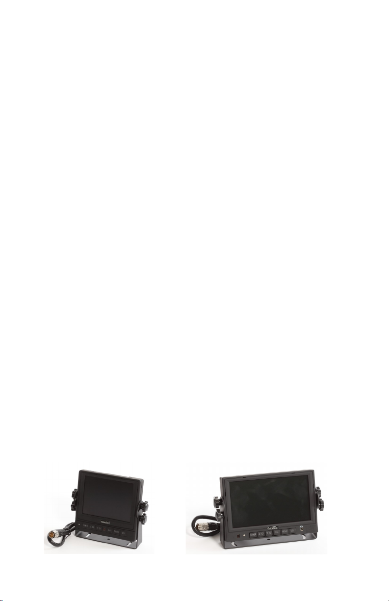
About the Monitor
The VisionStat Wired Monitor is a colored TFT LCD Monitor with a wide angle view and
a high resolution display. It supports both PAL and NTSC formats and the menu is
available in 8 languages. The buttons are equipped with automatic backlighting. The
Monitor can support up to 4 Cameras and can automatically switch to a specific Camera view via the trigger wires. The Monitor also includes a built in speaker and a full
function remote control.
The VisionStat Wired Monitor is available in two sizes, 5.6” and 7.0”.
Fig 1: 5.6” Wired Monitor
Fig 2: 7.0” Wired Monitor
6
Page 7
VisionStat 5.6” and 7.0” Wired Video Monitoring Systems
About the Cameras
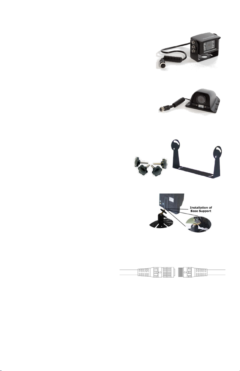
The standard Camera issued with the system is the 18IR
Camera which has a 120 degree viewing angle and is
rated IP68. This Camera comes equipped with 18 infrared
LEDs to provide night vision up to 12 meters. It is
mounted on a “U-Bracket” which allows the user to angle
the Camera up or down.
The Side Camera is typically featured in triple Camera
systems. This Camera comes equipped with 9 infrared
LEDs to provide night vision up to 8 meters. The
mounting bracket and protective cover is included with the
Camera.
For other Camera options and information, please visit
www.mobileawareness.com.
Installation: Monitor and Wiring Harness
Before installing the system, it is recommended to temporarily
connect all components and perform a system
function check. If the system does not operate
properly, see the troubleshooting section of this
manual. If further questions arise, please visit
www.mobileawareness.com or contact Mobile
Awareness directly.
The Monitor can be flush mounted in the dash
(with the included mount), with the “U-Bracket” and
thumb screws (see figure 4) or via the Dash Mount
Bracket (see figure 5). Make sure the mounting
location does not obscure the drivers viewing area.
Note: For other mounting options, please visit
www.mobileawareness.com
Fig 5: U Bracket and Thumb Screws
Fig 6: Dash Mount Bracket
Fig 3: 18IR Camera
Fig 4: Side Camera
The VisionStat system includes a 22-pin wiring harness. This wiring harness will power
the entire system, including the Monitor and up to 4 Cameras. Once the Monitor is
mounted, align the Monitor’s 22-pin
connection with the 22-pin connection of
the wiring harness. Each connector will
have an arrow to assist with the
alignment.
Fig 7: 22-pin Wiring Harness
Once engaged, slowly rotate the metal ring to thread the two connectors together. This
should be done with caution so that the connectors seat and thread together properly.
You may need to continue pressing the connectors together while rotating the metal
ring to facilitate the assembly. Following these steps will ensure the connection has
been made correctly. Failing to do so may cause problems with power, audio and
video connections. Twisting the cable, or the connectors themselves, to tighten the
connection may result in breakage of the pins and their connections, rendering the
wiring harness defective.
7
Page 8
Mobile Awareness
Installation: Monitor and Wiring Harness (Continued)
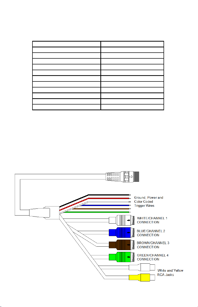
Before applying power to the system; make any Camera and trigger wire connections.
The 22-pin wiring harness’ wiring connections can be seen in the chart below. The
RCA connectors can be used to connect a second Monitor to the system for secondary
viewing.
The trigger wires can be used to achieve hands free operation for the VisionStat
system. For example, wiring the BLUE Trigger Wire to your right turn signal will
automatically toggle the Monitor to Channel 2 once the BLUE Trigger Wire receives
+12VDC. Once power is removed from the trigger wire, in this case the turn signal
being turned off, the Monitor will revert to the previous channel being displayed.
The most common use of the trigger wires, along with the turn signals, is using the
BROWN Trigger Wire to toggle the Monitor to Channel 3 to view the rear back up
Camera while in reverse, typically wiring it to the reverse lights. Keep in mind, the
desired Camera must be connected to the corresponding color.
White 4-pin Male Connection Camera/Channel 1
Blue 4-pin Male Connection Camera/Channel 2
Brown 4-pin Male Connection Camera/Channel 3
Green 4-pin Male Connection Camera/Channel 4
Red Wire +12-32VDC
Black Wire Ground
White Trigger Wire Trigger Wire for Channel 1
Blue Trigger Wire Trigger Wire for Channel 2
Brown Trigger Wire Trigger Wire for Channel 3
Green Trigger Wire Trigger Wire for Channel 4
Yellow RCA Video Output
White RCA Audio Output
Fig 8: 22 Pin Wiring Harness
8
Page 9
VisionStat 5.6” and 7.0” Wired Video Monitoring Systems
Installation: Cameras
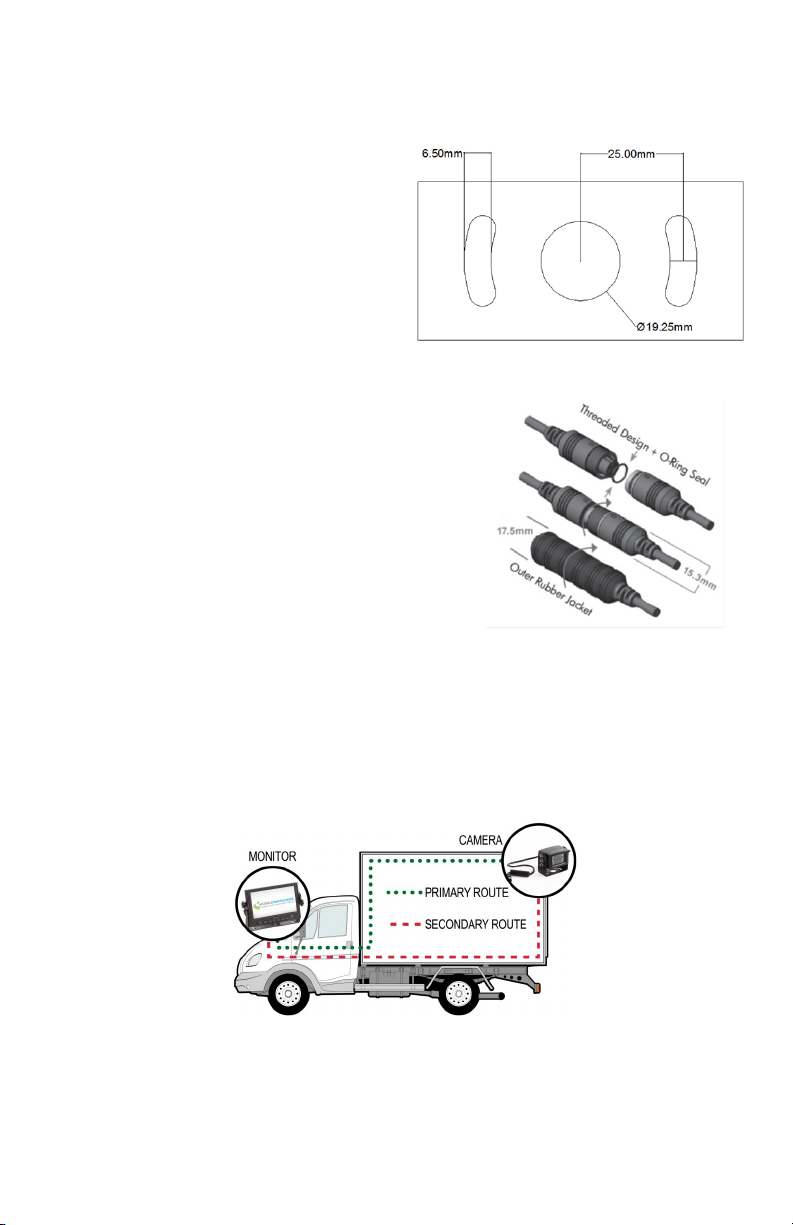
Each Camera will have a 4-pin connection and be connected to the Monitor’s 22-pin
wiring harness via an extension cable. The extension cables come in lengths of 5M,
10M and 20M. The length of the cable used
should be determined by the length of the
vehicle, including any passageway or route
you take through the vehicle’s body to
ensure a safe and secure connection.
Select a location to mount the Camera(s)
that allows for unobstructed viewing of the
area under consideration. It is important to
position the Camera so there is adequate
visibility without creating unrealized blind
spots. To aid in this effort, have an assistant
hold the Camera in the desired mounting
location while temporarily powering the system. This
will help ensure that the desired viewing area is
visible prior to mounting the Camera(s).
Most commercial vehicles are exposed to vibration
and other harsh impacts. Install the Camera in a
location where it will be secure. Take the necessary
measures to reinforce and securely support the
Camera if it will be exposed to uncommon amounts of
stress and/or vibration. It is suggested that the
Camera be mounted as high as possible to prevent
blind spots that result from it being installed too low to
the ground. Cameras installed low to the ground also
expose the lens to more dirt, mud, exhaust gasses,
etc.
The VisionStat wired system uses a series of 4-pin connections to connect the Camera
to the Monitor’s wiring harness. It is important that these connections are aligned
properly, using the arrows printed on the outer shell. Once the connection is pushed
together, the user should tighten the fastener and pull the rubber sleeve over for added
protection and to prevent loose connections.
NOTE: If using a truck and trailer, or
other two vehicle configuration, the
Fig 11: Extension Cable Paths
Truck & Trailer Interconnect will need to be used. This interconnect system is available
in both 1 camera and 4 camera versions. You will need to use the interconnect with
enough connections to support all cameras on the trailer or rear vehicle.
Fig 9: 18IR Mounting Bracket
Fig 10: 4-pin Connection
Fig 11: Examples of running the extension cables
9
Page 10
Mobile Awareness
Installation: Cameras (Continued)
If the Camera cable will run through the
vehicle body (see Figure 12), drill a 20mm
hole in order to pass the 4-pin connection
through. Once this connection is made, it may
be placed inside the vehicle body for
additional protection. The rubber grommet on
the Camera’s cable can be used to plug the
20mm hole. Seal the hole properly with
waterproofing compound, as well as
anywhere cables run through openings in the
vehicle body.
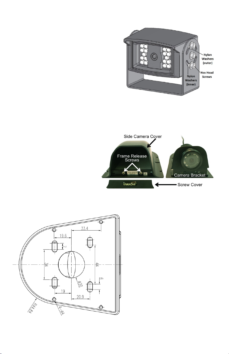
The Camera can be angled by loosening the
6 hex screws, 3 on each side, of the Camera.
Fig 12: Hex Screws on Side Camera
Once the desired angled is achieved,
retighten the 6 hex screws to secure the Camera.
Installation: Side Cameras
Once you have determined the most
effective mounting location, remove
the Frame Release Screws (2 each)
that hold the cover onto the Side
Camera Frame. Place the included
Rubber Insulating Pad in the
location where you plan to mount
the Camera and use it as a template
to mark and drill the (4 each)
mounting holes. Follow by drilling
the hole to pass the 4-pin Camera
cable connector through the vehicle.
Fig 13: Side Camera Mounting Bracket
Connect the included extension cable
(s) prior to mounting the Camera to
the Side Camera Frame. This will
allow you to thread the metal
connectors together, tighten them
securely and then slide the rubber
boot completely over the mated
connectors. This will assure a
watertight and trouble free connection.
When connecting to the Wiring
Harness, the left side Camera should
be connected to the WHITE Channel
One 4-pin Connector and the right
side Camera to the BLUE Channel
Two 4-pin Connector, via the included
extension cables.
Fig 14: Side Camera Mounting Bracket
10
Page 11
VisionStat 5.6” and 7.0” Wired Video Monitoring Systems
Installation: Side Cameras (Continued)
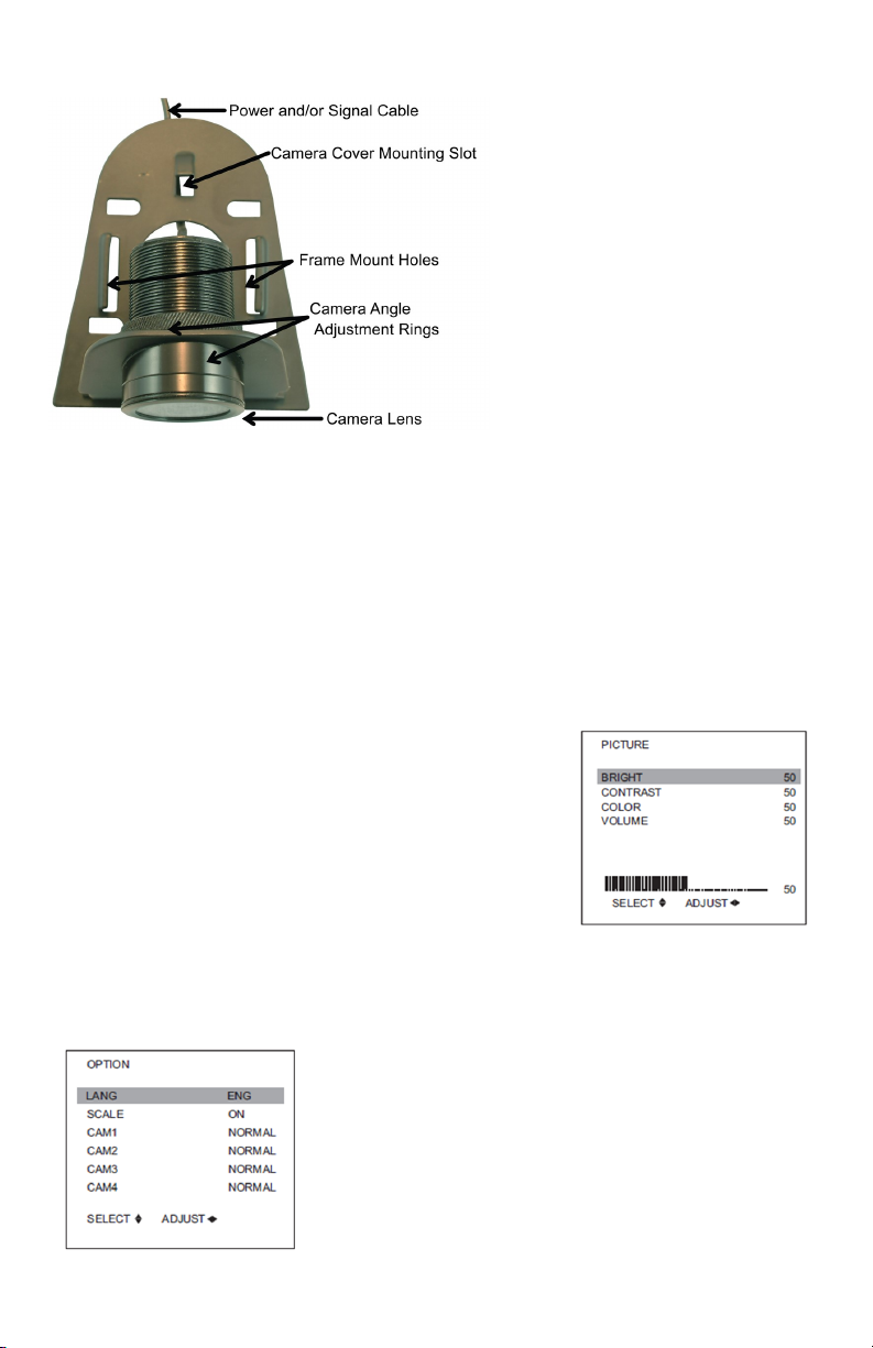
If the viewing angle needs to be
adjusted, loosen the Camera Body
Nut and rotate the Camera Angle
Adjustment Rings until the proper
viewing position is achieved. Once
properly positioned, hand tighten
the Camera body nut securely.
Carefully place the side Camera
cover over the side Camera frame
so that the front lip of the cover
slides under the Camera lens, while
the back portion of the cover slides
under the Camera cover mounting
slot. Once the cover is properly
seated on the frame, where the co-
Fig 15: Side Camera Mounting Bracket
vers edges fit within the lip of the
rubber insulating pad, replace and
secure the (2 each) frame release screws that hold the cover onto the side Camera
frame.
Carefully place the VisionStat logo clip on the lower front area of the side Camera assembly by snapping the two (2) prongs into the open slots to the right and left of the
frame release screws.
Menus
The Wired Monitors menu will consist of three screens:
1) Picture
2) Option
3) System
1) Picture: The Pict ure m enu wil l giv e you the option
of adjusting Brightness, Contrast, Color and Volume.
Press the CH– button on the Monitor to scroll up and
down to select your desired function. Press the ▲☼/▼☼
buttons on the Monitor in order to adjust the level of each
setting.
2) Option: The Option menu will give you the option of selecting Language, turn-
ing the backing scale on or off and turning any of the (up to 4) Cameras on or off.
Press the CH– button on the Monitor to scroll up and
down to select your desired function. Press the ▲☼/▼☼
buttons on the Monitor in order to adjust the level of each
setting.
11
Page 12
Mobile Awareness
Menu (Continued)
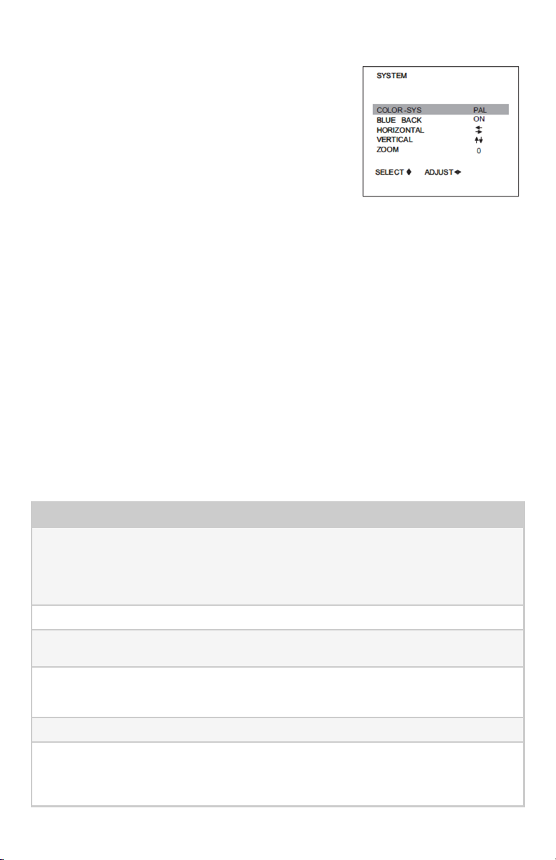
3) System: The System m enu will gi ve you the option
of which type of Color-System to use, turning the blue
Back Screen on or off, the horizontal and vertical adjust-
ments, as well as zoom.
Press the CH– button on the Monitor to scroll up and
down to select your desired function. Press the ▲☼/▼☼
buttons on the Monitor in order to adjust the level of each
setting.
Color System: Select between PAL/AUTO/NTSC
Blue Back: Select between turning the Blue Back Screen on or off. If turned off, the
screen will be black when a Camera feed is not present. If turned on, the screen will
be blue.
Horizontal: Adjusts the hor i zon tal alignment of the im age on the Monit or.
Vertical: Adjusts the vertical alignment of the image on the Monitor.
Zoom: Select between 16:9 (represented by a 0) and 4:3 (represented by a 1).
Maintenance & Troubleshooting
If the unit is not working properly, please review the following suggestions, prior to
contacting Mobile Awareness:
1) Double check all connections, including all 4-pin Camera and extension cable
connections, as well as the 22 pin wiring harness.
2) Check your power and ground connections. If utilizing a back-up Camera, be sure
the Brown Trigger Wire (from the 22-pin wiring harness) is connected to the vehi-
cle reversing light power source.
Symptom Possible Causes and Solution
No Picture or Sound Does the Monitor Power LED light up? If not, the
No Picture Ensure that Cameras are connected properly.
No Sound Ensure the volume is turned up to a desired level
Dark Picture Ensure brightness and contrast are adjusted cor-
No Color Adjust color settings.
Upside down or inverted picture Use the remote control horizontal/vertical selection
Monitor does not have power. This could be due to
using an improper power supply or a loose connection. If it is RED, the Monitor has power but is not
turned on. GREEN indicates the Monitor is on.
and not muted.
rectly. Check whether the environment temperature
is too low.
switch to set proper orientation. This can also be
done using the Menu button on the Monitor and
going to System settings.
12
Page 13

VisionStat 5.6” and 7.0” Wired Video Monitoring Systems
Maintenance & Troubleshooting (Continued)
Symptom Possible Causes and Solution
No reversing function Check that the correct corresponding color coded
trigger wire is connected properly. For example,
the rear Camera is typically connected to the
BROWN 4-pin connector, so the BROWN trigger
wire would need to be used to toggle the Monitor to
that channel, in this case, Channel 3.
Backing Safety Suggestions
A commercial truck has extremely limited visibility. A large area behind the truck is
invisible even with rear view mirrors properly adjusted. The larger the truck, the larger
the blind spot areas. The driver must become familiar with the trucks blind spot area(s)
so that precautions can be taken to avoid backing accidents. The best assurance to
avoid an accident is by paying close attention to your surroundings. In order to increase your chances of preventing a mishap, increase your level of awareness by considering the following:
(1) Stationary & Moving Objects: The driver sees Stationar y Object s i n t he r ear
view mirror before backing. However, as the truck backs, the objects may suddenly
disappear as the driver turns, or as these objects enter into the vehicles blind spot. No
matter how careful a driver may be by checking behind before backing, a moving ob-
ject such as a child, car or crewmember can move into the trucks blind spot unnoticed
by the driver. This is an extreme hazard; consider this whenever a truck is placed in
reverse.
(2) Never Backup without Concentrating: Backi ng i s ri sk y and requires the full
attention and skill of the driver. If a driver is unsure or does not know where crewmem-
bers are or where objects are behind the truck, do not back. STOP! Get out of the cab
and physically check the area.
(3) Walk the Vehicle before Backing: Walk around the vehic le to check the clearances and search for hidden obstacles before backing. Be aware of objects that ap-
pear above, in back and to the sides of the truck. Stop the vehicle and physically check
the area if in doubt of a safe clearance.
(4) Plan for Safety: Plan ahead t o circumvent backing situations whenever possible. Assign a helper to guide and signal in backing situations. Always keep the signal
person in view while backing to prevent hitting that person.
(5) Proceed Slowly: Always back slowly so that t he truck can be stopped immediately, if necessary. Slow backing will minimize damage if a backing accident occurs.
(6) Alert Pedestrians: Consider est ablishing the pr acti ce of honki ng your t ruck ’s
horn 2 times before backing. This signal will alert pedestrians, as well as crewmem-
bers to stay clear of your truck.
(7) Ultimate Responsibility: The driver of the vehicle has the f i nal responsibili ty
for safe backing. If you the driver are not sure whether the area behind the truck is
clear, stop the vehicle and get out to check.
13
Page 14

Mobile Awareness
Notes
14
Page 15
VisionStat 5.6” and 7.0” Wired Video Monitoring Systems
Complete Tire Management Solution
Obstacle Detection Sensor System
Vehicle Video System
Vehicle Video System with integrated Obstacle Detection
www.mobileawareness.com
1.866.653.5036
Specifications subject to change without notice.
Copyright © 2014 Mobile Awareness, LLC.
15
Page 16

www.mobileawareness.com BCKS-2102-INS-R2.1
 Loading...