

Vision Sensing ULVIPS series Operation Manuals
Operation Manual
Check
Y.Mito
Author
F.Ogawa
2012/7/2
1/19 .
SPD
-
1207
001 Visi
on Sens
i
ng Co. Ltd
ULVIPS series
Operation Manual
For up to Ver3.0
株式会社ビジョンセンシング
検 印 照 査 作 成
Vision
2010/11/24
水戸
Sensing
Vision
2010/11/24
大久保
Sensing
Vision
2010/11/24
嵯峨
Sensing

Operation Manual
Check
Y.Mito
Author
F.Ogawa
2012/7/2
2/19 .
SPD
-
1207
001 Visi
on Sens
i
ng Co. Ltd
Contents
ContentsContents
Contents
1: Application
1: Application1: Application
1: Application ................................................................................................................................ 3
2: UL
2: UL2: UL
2: ULVIPS camera overview
VIPS camera overviewVIPS camera overview
VIPS camera overview ............................................................................................................ 3
2.1: Mountable detector
2.1: Mountable detector2.1: Mountable detector
2.1: Mountable detector ............................................................................................................ 3
2.2: Video Signal Output
2.2: Video Signal Output2.2: Video Signal Output
2.2: Video Signal Output .......................................................................................................... 4
3: Detector
3: Detector3: Detector
3: Detector ...................................................................................................................................... 6
3.1 The careful point which is at the time of detector attachment
3.1 The careful point which is at the time of detector attachment3.1 The careful point which is at the time of detector attachment
3.1 The careful point which is at the time of detector attachment ......................................... 6
3.2 Cleaning method of the window
3.2 Cleaning method of the window 3.2 Cleaning method of the window
3.2 Cleaning method of the window of the detector
of the detectorof the detector
of the detector ............................................................ 6
4: Connection method with the camera connector
4: Connection method with the camera connector4: Connection method with the camera connector
4: Connection method with the camera connector ..................................................................... 7
4.1 Connector location
4.1 Connector location4.1 Connector location
4.1 Connector location .............................................................................................................. 7
4.2 Connector pin assignment
4.2 Connector pin assignment4.2 Connector pin assignment
4.2 Connector pin assignment ................................................................................................... 8
4.3: About a trigger input pin outside the 4.3: and the outside control pulsed output pin.
4.3: About a trigger input pin outside the 4.3: and the outside control pulsed output pin.4.3: About a trigger input pin outside the 4.3: and the outside control pulsed output pin.
4.3: About a trigger input pin outside the 4.3: and the outside control pulsed output pin. .. 9
4.4: Camera connecting
4.4: Camera connecting4.4: Camera connecting
4.4: Camera connecting ............................................................................................................ 10
4.5: Camera connecting when using external trigger and digital output.
4.5: Camera connecting when using external trigger and digital output.4.5: Camera connecting when using external trigger and digital output.
4.5: Camera connecting when using external trigger and digital output. ............................ 10
5: H
5: H5: H
5: How to operate ShutterlessViewer
ow to operate ShutterlessViewerow to operate ShutterlessViewer
ow to operate ShutterlessViewer ......................................................................................... 11
5.1: Display overview
5.1: Display overview5.1: Display overview
5.1: Display overview ............................................................................................................... 11
5.2: Capturing image
5.2: Capturing image5.2: Capturing image
5.2: Capturing image................................................................................................................. 12
5.3: Select shutterless table
5.3: Select shutterless table5.3: Select shutterless table
5.3: Select shutterless table ...................................................................................................... 13
5.4: Measurement temperature range
5.4: Measurement temperature range5.4: Measurement temperature range
5.4: Measurement temperature range ..................................................................................... 13
5.5: Display window
5.5: Display window5.5: Display window
5.5: Display window ................................................................................................................. 15
5.6: Sampling function
5.6: Sampling function5.6: Sampling function
5.6: Sampling function ............................................................................................................ 16
5.6.1: Sampling window
5.6.1: Sampling window5.6.1: Sampling window
5.6.1: Sampling window ........................................................................................................ 16
5.7: Save current display
5.7: Save current display 5.7: Save current display
5.7: Save current display image
imageimage
image ............................................................................................... 18
Update records. ............................................................................................................................. 19

Operation Manual
Check
Y.Mito
Author
F.Ogawa
2012/7/2
3/19 .
SPD
-
1207
001 Visi
on Sens
i
ng Co. Ltd
1111:::: Application
ApplicationApplication
Application
This document is applied about standard shutterless camera application when estimating a
ULVIPS camera.
* When the
* When the * When the
* When the camera version isn't more than 3.0, it's necessary to do an update.
camera version isn't more than 3.0, it's necessary to do an update.camera version isn't more than 3.0, it's necessary to do an update.
camera version isn't more than 3.0, it's necessary to do an update.
* CameraVervion3.0 and a written sticker are stuck on an applied camera.
* CameraVervion3.0 and a written sticker are stuck on an applied camera.* CameraVervion3.0 and a written sticker are stuck on an applied camera.
* CameraVervion3.0 and a written sticker are stuck on an applied camera.
2:
2: 2:
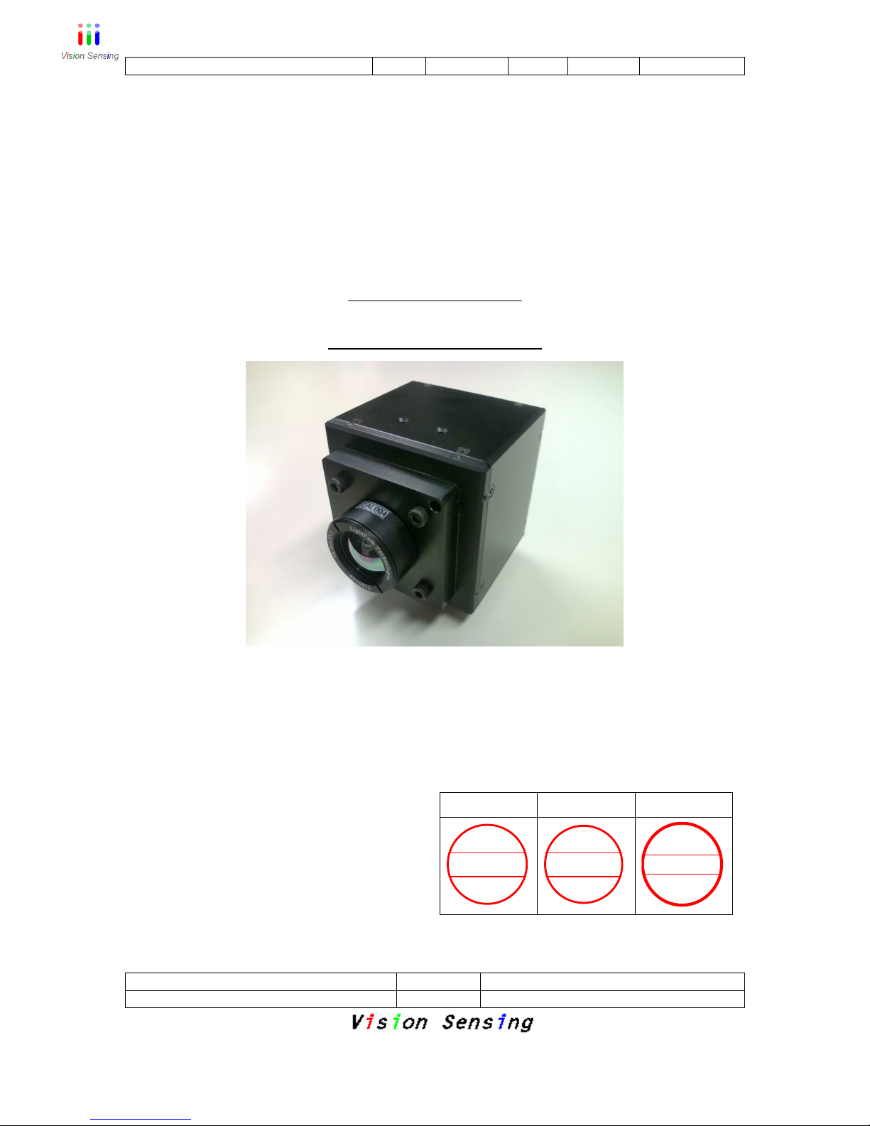
2: ULVIPS
ULVIPSULVIPS
ULVIPS camera overview
camera overviewcamera overview
camera overview
2.1: Mountable detector
2.1: Mountable detector2.1: Mountable detector
2.1: Mountable detector
UL02 152 (Pixel number: 160 x 120)
UL03 162 (Pixel number: 384 x 288)
UL03 262 (Pixel number: 384 x 288)
UL04 171 (Pixel number: 640 x 480)
UL04 272 (Pixel number: 640 x 480)
UL05 251 (Pixel number: 1024 x 768)
Operation Manual
Check
Y.Mito
Author
F.Ogawa
2012/7/2
4/19 .
SPD
-
1207
001 Visi
on Sens
i
ng Co. Ltd
2.2: Video Signal Output
2.2: Video Signal Output2.2: Video Signal Output
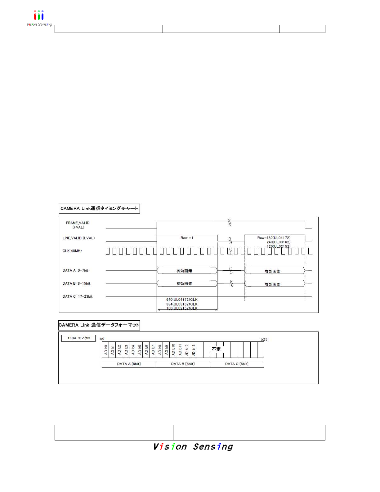
2.2: Video Signal Output
1.
1. 1.
1. Cameralin
CameralinCameralin
Cameralink Output
k Outputk Output
k Output
Pixel clock: 48MHz
Image bit size: Maximum 14bits
Maximum frame rate
UL03 162/262: 50fps
UL02 152: 60fps
UL04 171: 60fps
UL04 272: 50fps
UL05 251: 60fps
Cameralink Signal Format
It is synchronized with FVAL of the cameralink standard and send a frame
of picture. It is synchronized with LVAL and send a line of picture.
DVAL isn't used.
* Applied grabber board
DALSA:X64-CL/X64-CL iPro/X64 Xcelera-CL LX1
You can get image through cameralink, by using “Sapera Cam

Operation Manual
Check
Y.Mito
Author
F.Ogawa
2012/7/2
5/19 .
SPD
-
1207
001 Visi
on Sens
i
ng Co. Ltd
Export” which attached this grabber board.
*Camera configuration file
A setting file of a grubber board is different in CameraLink
output depending on the sensor sizes.When doing picture
confirmation in Sapera Cam Export, please use the following
camera setting file "*.ccf".
UL02 152 ULVIPS02152.ccf
UL03 162/262 ULVIPS03162.ccf
UL04 171 ULVIPS04171.ccf
UL04 272 ULVIPS04272.ccf
UL05 251 ULVIPS05251.ccf
These files are in Installation CD.
2. USB Output
2. USB Output2. USB Output
2. USB Output
It's possible to get image through USB. It corresponds to only this application.
The frame ratio when getting image is depend on PC specification.
Operation Manual
Check
Y.Mito
Author
F.Ogawa
2012/7/2
6/19 .
SPD
-
1207
001 Visi
on Sens
i
ng Co. Ltd
3: Detector
3: Detector3: Detector
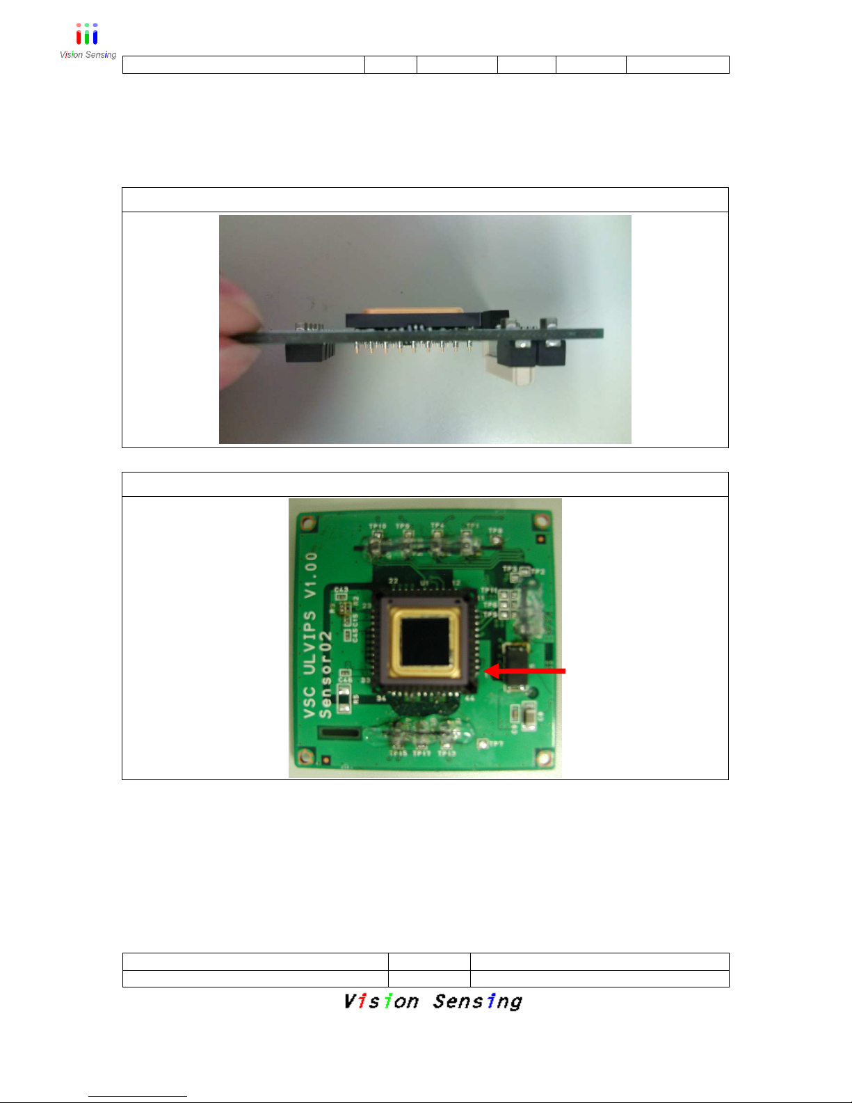
3: Detector
3.1 The careful point which is at the time of detector attachment
Please put a detector in tight like the following picture.
For UL03 162/262,UL04 272
For UL02 152
*
* *
* When exc
When excWhen exc
When exchanging a sensor, please be sure to remove after the powersupply is
hanging a sensor, please be sure to remove after the powersupply is hanging a sensor, please be sure to remove after the powersupply is
hanging a sensor, please be sure to remove after the powersupply is
cut.
cut.cut.
cut. When exchanging the kind of sensors, all set values which were being
When exchanging the kind of sensors, all set values which were being When exchanging the kind of sensors, all set values which were being
When exchanging the kind of sensors, all set values which were being
preserved inside the camera return to defaults.
preserved inside the camera return to defaults.preserved inside the camera return to defaults.
preserved inside the camera return to defaults.
3.2
3.2 3.2
3.2 Cleaning method of the window of the detector
Cleaning method of the window of the detectorCleaning method of the window of the detector
Cleaning method of the window of the detector
Please wipe up isopropyl alcohol and deionized water by soft cloth using the one
divided by 1:1.
Of a sensor, please
adjust a pin to this
point.
 Loading...