

Vision Research Phantom VEO 340, Phantom VEO 640, Phantom VEO 410, Phantom VEO 710 User guide
VEO & VEO4K CAMERAS
340 | 640 | 410 | 710 | 590 | 990 | PL | S and L Models
VEO MANUAL
When it’s too fast to see, and too important not to.
®

w w w . p h a n t o m h i g h s p e e d . c o m
Phantom VEO Manual
PN: ZDOC-64109-MA-0001 Rev B
Last Updated: January 2018

when it’s too fast to see, and too important not to.
Phantom VEO
MANUAL
®
VEO 340, 640, 410, 710
S and L body styles
100 Dey Road
Wayne, NJ 07470 USA
+1.973.696.4500
www.phantomhighspeed.com
Including models
VEO4K 590, PL, 990

w w w . p h a n t o m h i g h s p e e d . c o m
Phantom VEO Manual
Written and produced by the Marketing Department at Vision Research.
The contents of this manual may be subject to change without notification.
PN: ZDOC-64109-MA-0001 Rev B
Last Updated: January 2018

Contents
Camera Overview
1
Connectors
2
Network Setup & Quick Start Guide; Includes 10Gb
3
Ethernet instructions
On-Camera Controls and On-Screen Displays
4
Working with CFast 2.0 Cards
5
Phantom PCC Software: Camera Operation,
6
Download and File Conversion
Programmable I/O Signal Architecture
7
Measurements with PCC
8
Accessories
9
FAQs & Support
10
1
5
9
15
27
31
45
51
57
67

VEO 710
VEO 410
VEO 640
VEO 340
VEO4K 990 & PL
VEO4K 590
Max. Resolution
FPS @ Max Res
Throughput
Sensor Size
@ Full Res
Pixel Pitch
CAR
Min. Exposure
Straddle Time
Native ISO
(12232 SAT Method)
Recommended
Exposure Index (E.I.)
Memory
Power
Size/ Weight
specifications
Operational Temp
Shock Rating
1280 x 800 2560 x 1600 4096 x 2304
7400 fps (710);
5200 fps (410)
7Gpx/sec (710);
5Gpx/sec (410)
25.6 x 16 mm (super 35mm) 27.6 x 15.6 mm
20 micron 10 micron 6.75 micron
64 x 8 128 x 4 4096 x 4
1 μs standard, 300ns optional on 710 models only 5.6 μs
395 ns (710);
480 ns (410)
Mono: 6400
Color: 2000
Mono: 6400 - 40,000;
Color: 2000 - 10,000
18GB, 36GB or 72GB RAM 36GB or 72GB RAM
16-32 VDC primary power, power supply included. Secondary 12V input on S-models only
Approx. 5 x 5.5 x 5 in (12.7 x 12.7 x 12.7 cm)
5.6 lbs (2.5 kg)
Rated 30G (standard); 100G without shutter (optional)
1400 fps (640);
800 fps (340)
6Gpx/sec (640);
3Gpx/sec (340)
1.73 μs (640);
1.71 μs (340)
Mono: 6400
Color: 1250
Mono: 6400 - 40,000;
Color: 1250 - 6400
-10° - +50° C
938 fps (990);
530 fps (590)
9Gpx/sec (990);
5Gpx/sec (590)
7.5 μs (typical)
3.7 μs w/ GS & PIV mode
Mono: 2500 (GS); 1000 (RS)
Color: 640 (GS); 320 (RS)
Mono: 4000 - 8000 (RS/GS)
Color: 800 - 1000 (RS/GS)
Approx. 5 x 5.5 x 6 in
(12.7 x 14 x 15 cm) 6.5 lbs (2.9 kg)
‘L’ style
‘S’ style
Phantom VEO Manual
Ethernet Video
1 GbE with
10GbE option,
RJ45 port
1 GbE with
10GbE option,
Fischer port
Front 3G SDI
Din & HDMI
Same as L
w/ additional
3G SDI BNC
OCC/
Buttons
None None 2 Ports None
Full OCC menu
+ Trigger &
Play buttons
CFast
Media
Supports CFast
2.0 cards up
to 256G
Programmable
I/O
4 Ports
Range
Data
Yes,
Dedicated
Fischer port
1
Camera Overview
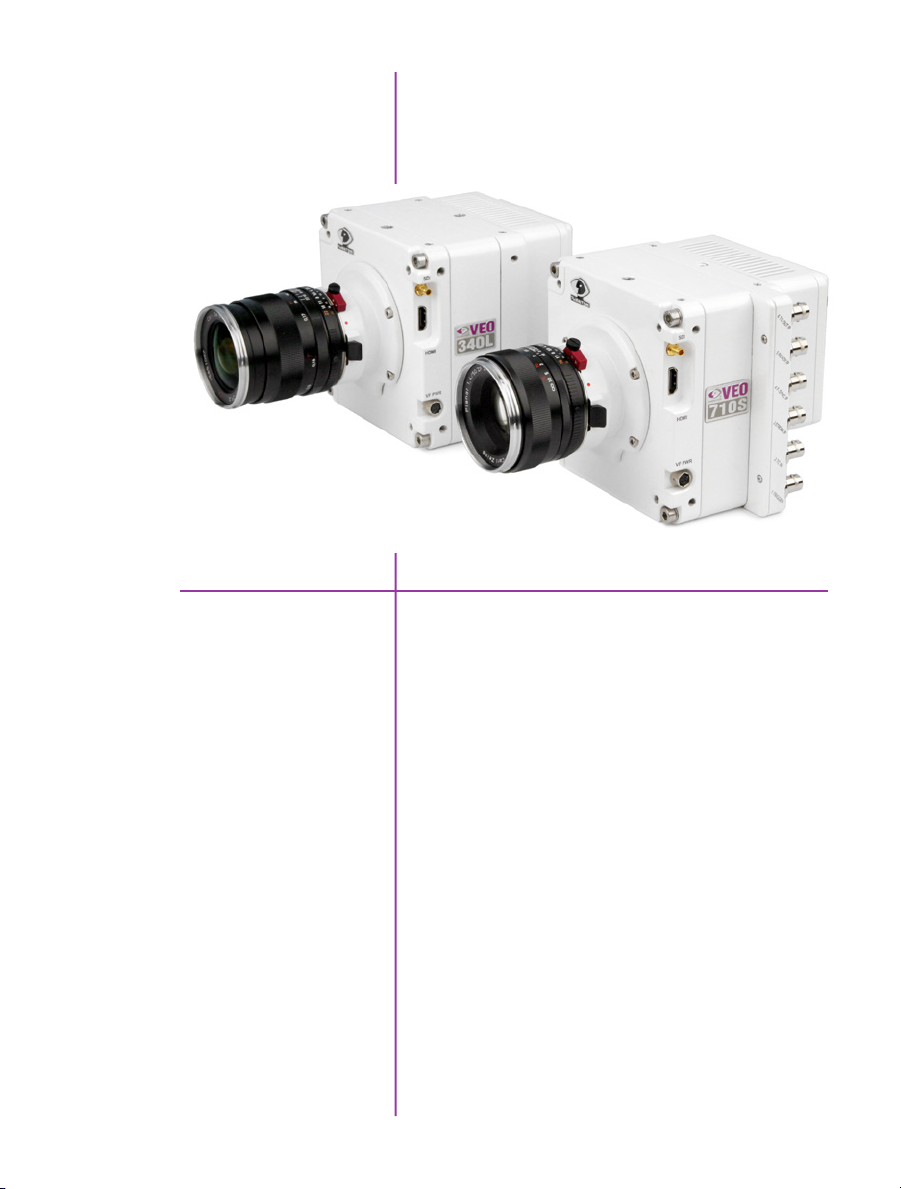
Phantom VEO 340L and 710S
Introduction
Phantom VEO high-speed cameras are small, rugged,
packed full of features and available in several
performance levels and two body styles (L and S).
VEO 410 and 710 models use a one-megapixel sensor.
At 1280 x 800 the VEO 410 captures over 5,000 frames
per second (fps) and the VEO 710 goes over 7,000 fps.
Like all Phantom cameras, the lower the resolution the
faster the camera can record. At 720p the VEO 710
reaches 8,000 fps. With the fast option installed the VEO
710 records over 1,000,000 fps at a reduced resolution.
The Phantom VEO 340 and 640 use a four-megapixel
sensor. The VEO 640 goes over 1,400 fps at full resolution
and over 2,500 fps at 1920 x 1080.
VEO4K cameras utilize a 9.4-megapixel sensor. PL and
990 models will capture up to 1,000 fps at 4K resolution.
1
Chapter 1: Camera Overview

Sensitivity & Exposure Index
VEO cameras use proprietary 12-bit CMOS sensors
designed for optimal image quality and light sensitivity.
The camera’s Exposure index function allows for the
effective ISO to be dialed in either on the camera body
or in PCC software.
This function applies pre-defined tone curves to the
image, providing an apparent boost to the ISO while
maintaining image integrity across the full tonal range.
VEO4K models are configured to capture images using
either a Rolling Shutter or Global Shutter. Global Shutter
mode has a higher base-ISO than Rolling Shutter (640
vs 320). By using the Exposure Index function both
modes can capture at the same ISO level, and the factory
recommendation is between 800-1000 EI for color
cameras in both modes.
Lens Mounts
Camera Control
CFast 2.0 Workflow
All models have a super 35mm field of view at full
resolution and are compatible with common SLR lenses
when equipped with the standard Nikon or optional Canon
EF lens mount. The Canon mount allows for electronic and
remote control of aperture and focus. A PL mount and
C-mount are also available for VEO cameras.
All Phantom VEO cameras come with PCC software for
setup and control over an Ethernet network. VEO S-model
cameras also have an On-Camera Control (OCC) menu
system for use with an attached video monitor. The
OCC menu can adjust both basic and advanced camera
settings. Capture, Play and Save-to-CFast functions are
also available via the camera’s OCC menu.
VEO S-model cameras are compatible with standard CFast
2.0 cards. CFast cards are non-volatile, hot-swappable
recording media and they enable remote, un-tethered
recording. The cards must be formatted with the NTFS file
system - this can be done either in-camera or in a CFast
2.0 card reader on a PC or Mac.
Once images have been captured in RAM they can be
played back immediately, in/out points set and then saved
to the CFast card at speeds of approximately 90 MB/
second.
2
Phantom VEO Manual

File Formats
Like all Phantom cameras, Phantom VEO utilizes Vision
Research’s proprietary Cine Raw format. These files are
captured in 12-bit and efficiently saved to the CFast 2.0
card in a 10-bit ‘packed’ format.
Cine Raw files can be viewed and edited in PCC software,
where basic motion analysis measurement tools are
available. An SDK and file format documentation are
available for users who require Phantom Cine file
compatibility in independent software.
Cine Raw files are compatible with many of the video
industry’s top editing programs, or they can be converted
to a variety of formats (h264 .mp4, Apple ProRes .mov,
.avi, tiff, etc) using software provided with the camera.
Image Monitoring & Video Outputs
Additional Features
All Phantom VEO camera models have a 3G HD-SDI,
HDMI and 12V power output from the side of the camera.
These make it easy to use a small on-camera monitor or
viewfinder for composing the shot and watching a smooth
playback without being tethered to a computer.
VEO S-models have a second 3G HD-SDI BNC port on
the back of the camera. The feed from all video outputs is
identical and can show either live video or playback.
10Gb Ethernet Option: The fastest way to download data
from from RAM
Programmable I/O: Assign and Define signal
parameters. See Progammable I/O section for more info.
Image-Based Auto-Trigger (IBAT): Trigger camera from
change in image
Multi-Cine: Support for up-to 63 partitions
Burst Mode: Generate a precise number of frames with
every frame sync pulse. This feature is not available with
VEO4K models.
Continuous Recording: Automatically and continuously
save Cines to external storage
Chapter 1: Camera Overview
3

A
B
VEO-L
C
4
Phantom VEO Manual
D I
E
F G H
Phantom VEO-L Models - Side and Rear Views
Connectors
2
SDI
HDMI
VF PWR
2 TC In
5 I/O
+16 - 32 VDC
Ethernet
1 Trigger
3 I/O
VEO-L Models
Din (mini-bnc) connector outputs SDI video at 1.5G
A
and 3G video rates.
Standard HDMI connector - outputs identical digital
B
video signal as SDI.
C
4-pin Hirose port. +12V power output for small
monitors and viewfinders, rated up to 10W.
Timecode-in BNC - fixed port.
D
Programmable I/O BNC port. Port ID = P5 Default signal
E
is Strobe.
6-pin Fischer port for main power input, accepts +16
F
- 32 VDC.
RJ45 port for Gb Ethernet, for control and data transfer.
G
Trigger-in BNC - fixed port.
H
Programmable I/O BNC port. Port ID = P3 Default signal
I
is F-Sync.
Assign and define Programmable I/O
ports using PCC.
Instructions can be found in the
Progammable I/O section of this manual.
A complete cable connector reference and
pin-out guide is available in the last section
of this manual
Chapter 2: Connectors
5

J
K
VEO-S
L
M
N
6
Phantom VEO Manual
O
P
Q
R
S
T
U
V
W
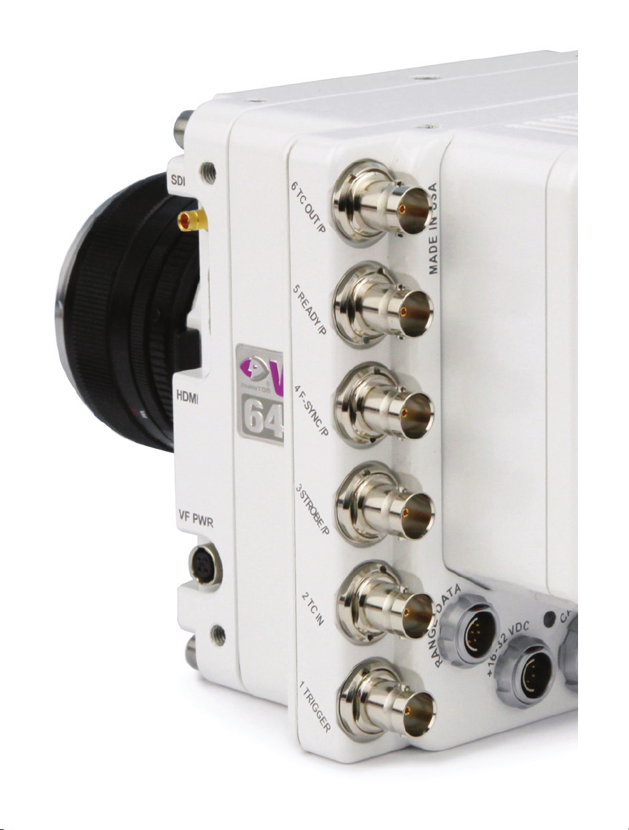
Phantom VEO-S Models - Side and Rear Views
X
Y

VEO-S Models
SDI
HDMI
VF PWR
6 TC Out /P
5 Ready /P
4 F-Sync /P
3 Strobe /P
2 TC In
1 Trigger
CFast Port
Range Data
Din (mini-bnc) connector outputs SDI video at 1.5G
J
and 3G video rates.
HDMI video output.
K
4-pin Hirose port. +12V power output for small
L
monitors and viewfinders, rated up to 10W.
Programmable I/O BNC port. Port ID = P6 Default signal
M
is Timecode Out.
Programmable I/O BNC port. Port ID = P5 Default signal
N
is Ready.
Programmable I/O BNC port. Port ID = P4 Default signal
O
is F-Sync.
Programmable I/O BNC port. Port ID = P3 Default signal
P
is Strobe.
Timecode-in BNC - fixed port.
Q
Trigger-in BNC - fixed port.
R
CFast 2.0 Card slot.
S
8-pin Fischer port for Range data input.
T
+16 - 32 VDC
Capture / +12VDC In
Ethernet
SDI
USB Port
6-pin Fischer port for main power input, accepts +16
U
- 32 VDC.
12-pin Fischer port for capture cable or mini-bob
V
accessories, or use as a secondary +12V power input
for battery adapters.
8-pin Fischer port for Gb Ethernet, for control and data
W
transfer.
BNC port for 1.5G and 3G SDI video output.
X
USB port - For WiFi dongle (Requires chipset RT5370)
Y
7
Chapter 2: Connectors

8
Phantom VEO ManualPhantom VEO Manual
This section shows basic setup and camera control using
Phantom PCC software. More in depth instructions can
be found later in this manual. Please note there are other
methods of camera control including on-camera controls,
the Phantom Remote Control unit (RCU) and various 3rd
party solutions.

Network Setup &
3
Gb & 10Gb Ethernet
Quick Start Guide
Phantom cameras are typically controlled with PCC
software through a dedicated Ethernet network. PCC is
compatible with the 32 and 64-bit versions of Windows
7 Pro, Windows 8.1 and Windows 10 operating systems.
The latest version can be downloaded at:
www.phantomhighspeed.com/pcc
All VEO cameras come with standard Gigabit (Gb) Ethernet
and have the option to be configured with 10-Gigabit
(10Gb) Ethernet as a secondary means of connection.
With 10Gb Ethernet, the VEO can achieve significantly
higher download speeds which makes it a great option for
saving large files quickly out of RAM.
VEO cameras have one Ethernet port which handles both
protocols. The camera will auto-negotiate the connection
speed based on the computer’s network card and its IP
configuration as described later in this section.
First, check to see if your VEO has the 10Gb Ethernet
option installed by looking at the Serial Number and IP
Address label on top of the camera. If installed, ‘10G’ will
be printed on the label, in addition to an ‘XIP’ address that
begins with 172.16 as pictured.
Assigning a Gb Camera Network
Connecting the VEO with standard Gb Ethernet is straight
forward, as virtually all computers will be compatible with
no special equipment or drivers involved. The main thing
that needs to be done is to re-assign the network settings
of the Ethernet port to detect the IP address range of
Phantom cameras.
9
Chapter 3: Quick Start Guide

1. In the Windows ‘Network and Sharing Center’
select the camera network, this opens the ‘Ethernet
Status’ window (Note: For Laptops without a built-in
RJ45 port the adapter may have to be physically
connected before selecting the network)
2. Change the Ethernet IP settings by selecting
‘Properties’, then ‘TCP/IPv4’ ‘Properties’, then
select ‘Use the following IP address,’
3. Enter:
• IP address: 100.100.100.1
• Subnet mask: 255.255.0.0
All other settings should be empty
Click ‘OK’
4. Ensure the Windows Firewall is disabled for this
connection
You can now start PCC, which should recognize the
connected camera in the Manager tab. If you are not
working with 10Gb, skip to the ‘Capturing a Cine’ section
below.
Step 1: Identify network adapter
10
Phantom VEO ManualPhantom VEO Manual
10Gb Ethernet
On cameras with the 10Gb Ethernet option, the first step
to working with this feature is to identify a 10GBase-T
network card or adapter for the computer itself.
For desktop (tower) PCs Vision Research specifically
recommends the Intel X540-T2 PCIE card.
Laptop computers must have a Thunderbolt connection
available in order to take advantage of one of the many
Thunderbolt →10Gbase-T converters on the market.
At the time of writing, the recommended converter is
the Promise Sanlink2 10Gbase-T converter (part #
SLE2002TNAA). This device has 2 Thunderbolt 2 ports.
This means if your computer has a newer Thunderbolt
3 connection a secondary adapter is required to convert
the Thunderbolt 2 to a Thunderbolt 3 port. For this, the
StarTech Thunderbolt 3 to 2 adapter is recommended
(part # TBT3TBTADAP).
Note: At the time of writing, the newer Sanlink 3 is not fully compatible with
Phantom products. Other devices have tested well, including the Sonnet Twin 10G
Thunderbolt 3 converter (part # SOTWIN10TB3), however the Sanlink 2 is physically
smaller.

Step 2: Install device driver
Once the network card or converter is connected, the
next step is to install the latest device driver from the
manufacturer’s website. The camera should be powered
on and connected during the driver installation. After the
driver is installed, reboot the PC.
A new, unidentified camera network should now be
available in the Windows Network and Sharing Center.
Step 3: Install PCC with 10Gb
Phantom driver
Step 4: Assigning a 10Gb
Camera Network
The latest version of PCC software should now be installed
from the disk that came with the camera or by running
the setup.exe file within the package downloaded (and
extracted) from www.phantomhighspeed.com/pcc
Click through the prompts, and be careful to click ‘YES’
when the program prompts you to install the 10 Gigabit
Ethernet Driver.
Just like assigning the 100.100 IP range for standard Gb
Ethernet, the Phantom 10Gb Ethernet network needs to
be assigned to work in the 172.16 IP range. The camera
should be powered on and physically connected to the
10Gb network card or Thunderbolt adapter.
1. In the Windows ‘Network and Sharing Center’
select the camera network. This opens the ‘Ethernet
Status’ window.
2. Change the Ethernet IP settings by selecting
‘Properties’, then ‘TCP/IPv4’ ‘Properties’, then
select ‘Use the following IP address,’
3. Enter:
• IP address: 172.16.0.1
• Subnet mask: 255.255.0.0
All other settings should be empty
Click ‘OK’
4. Ensure the Windows Firewall is disabled for this
connection
Capturing a Cine
Now that the camera network is set up (via Gb or 10Gb
Ethernet), the following steps will guide you through a
simple capture and save process.
11
Chapter 3: Quick Start Guide

Launch PCC Software
Double-click the PCC icon located on the desktop. Camera
should be recognized immediately if connected and
network settings are correct.
Select Camera for Use
Define Recording
Parameters
In the ‘Manager’ tab, double-click the Phantom camera to
be used from the ‘Cameras’ group folder.
Click the ‘Live’ tab.
Click ‘Cine Settings’ and define the following parameters
by either selecting the value from the pull-down selection
list, or type a value into the respective data entry field.
1. Set ‘Resolution’ to the required Width x Height
2. Choose the required ‘Sample Rate’, ‘Exposure Time’
and ‘Exposure Index’
3. Ensure the EDR (Extreme Dynamic Range) is set to
zero (0).
4. Set Post Trigger to zero (0) by:
a. Moving the ‘T’ (Trigger Position) slider to the right,
or
b. Enter zero (0) into the ‘Last’ data entry field.
Click on the CSR button to perform a Current Session
Reference.
With color cameras, perform a White Balance by rightclicking an area of the image that is neutral gray or white,
as long as it is not 100% saturated.
12
Phantom VEO ManualPhantom VEO Manual
Fine-tune Settings
‘Arm’ Camera
Trigger
After CSR and White balance are performed, adjust
settings, aperture and/or lighting to get a good exposure.
A CSR must be performed after any camera settings are
adjusted.
Click the ‘Capture’ button to start recording to the
camera’s internal RAM memory (circular buffer).
At the end of the action, click the ‘Trigger’ button at the
bottom of the ‘Live’ panel, or provide a switch closure
or an external trigger signal (TTL pulse) via the Trigger
connector.

Playback and Edit Cine
Click the ‘Play’ tab.
Scrub through the timeline or use the Video Control
Buttons to locate the first image to be saved.
Click the ‘Mark-in’ button.
Locate the last image of the cine to be saved.
Click the ‘Mark-Out’ button.
Review Edited Cine
Save to Computer
Save to CFast
(optional)
Select ‘Play, Speed & Options’ and enable (check) ‘Limit
to Range’.
Under the Video Control Buttons, click the ‘Jump to Start’
button and review the edited cine using the Video Control
Buttons.
Click the big ‘Save Cine...’ button on the bottom of the
‘Play’ panel.
In the ‘Save Cine’ window:
1. Navigate to the folder where you want to save the
cine file.
2. Enter a file name for the cine file in the ‘File name:’
data entry field.
3. From the ‘Save as type’ pull-down selection list,
select the ‘Cine Raw, *.cine’ file format.
4. Click the Save button to begin downloading the cine
file from the camera.
Click the down-arrow of the ‘Save Cine...’ button.
Select ‘Save RAM Cine to Flash’ (in popup window).
Click the Save button to save the cine file onto the CFast
2.0 card
Confirm Computer Save
Confirm Flash Cine Save before deleting from internal
memory. Select the new Flash Cine from the top Play/Cine
drop-down list and scrub through cine file to review.
Click the ‘Open File’ button
Navigate to the folder and open saved cine file. Review
the playback by scrubbing through the file and viewing the
playback.
13
Chapter 3: Quick Start Guide
A
VEO-S OCC
B
C
D
E
14
Phantom VEO Manual
Use of the VEO-S on-camera control menu requires
a video monitor to be connected to the camera. VEO
cameras are compatible with HDSDI and HDMI monitors.
The combination of a VEO battery mount, a small
camera-powered on-camera monitor and CFast cards
creates a fully portable, un-tethered camera system.
More details can be found in the accessories section
of this manual or at www.phantomhighspeed.com

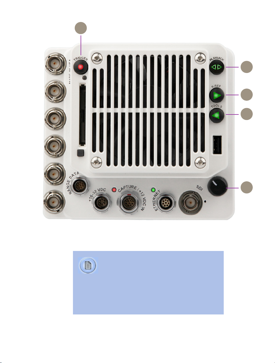
On-Camera
4
Trigger
Playback
B-Ref
Controls
When camera is in capture mode (writing to internal
A
RAM), button glows red. Trigger is used to trigger the
camera with a single tap. When a Cine is captured,
button glows green.
When in video playback mode, tap the trigger button to
return to a live video output.
When menu is active, tap the trigger button to exit the
menu.
To clear previous recording from RAM and re-enter
capture mode, hold down the trigger button for 4
seconds.
Tap to enter playback mode when a cine is stored in
B
RAM. Playback buttons will glow green when camera is
in playback mode.
In live mode, a long press of the B-Ref button will
C
perform a Current Session Reference (CSR). When in
playback mode, the play-forward symbol is illuminated
and this button is used to play forward. A long press will
do a fast-forward. Tap to pause.
Tools
Menu Knob
In live mode, a tap of the Tools button will cycle through
D
video zoom levels (for focus assist) and threshold
(exposure assist) mode. When in playback mode, the
play-backward symbol is illuminated and this button is
used to play reverse. A long press will do a fast-reverse.
Tap to pause.
Tap the menu button to activate the camera’s menu
E
system as described on the following pages. Turn the
knob to navigate through the menu, and tap to select.
Exit the menu by waiting 10 seconds or tapping the
trigger button.
Chapter 4: On-Camera Controls
15
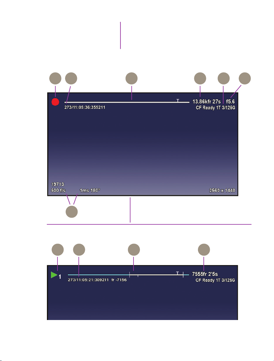
OSD Overview
Video display, Live mode
F G H KJI
The On-Screen Display (OSD) provides valuable
information about the camera’s current status over the
video outputs along with the live or playback images.
on-screen displays
16
Phantom VEO Manual
L
Video display, Playback mode
M N O P

Camera State
The symbol changes based on camera’s state:
F
Live: The camera is not recording and a live image is
displayed from all SDI ports.
Capture: The camera is recording to internal memory
(RAM), and awaiting a trigger signal.
Triggered: The camera has been triggered, and is
filling RAM memory (‘Post-Trigger’ frames).
Cine Stored: Recording has ended, and a Cine is
stored in RAM memory. This Cine must be erased from
the RAM to begin recording again.
Playback: The camera is in PLAYBACK mode. RAM
Cines can be reviewed, edited and saved to flash.
Timecode
Buffer Bar w/ Trigger Point
Frame Count and Duration
Flash Memory Status
EF Lens Aperture Data
Capture Settings
RAM Cine Indicator
Playback bar
Playback Timecode
Indicates the IRIG time code stamped to each frame.
G
Format is day of year/hour:minute:second:ns.
This ‘time line’ represents all frames available in
H
camera RAM (Loop mode) The ‘T’ indicator represents
the user-defined trigger point.
Displays the frame count and recording time based on
I
the current camera settings.
Indicates the memory size of the CFast card (if present)
J
and the total recording time available.
Displays the F-Stop (aperture) of the lens (valid for
K
Canon EF mount only).
Bottom section of display shows camera name, frame
L
rate, exposure time (displayed in degrees and microseconds) and the acquisition resolution.
Indicates RAM Cine number selected for playback.
M
Playback bar is a visual representation of the Cine
N
timeline with the trigger point (T), mark-in and mark-out
(I) points and play head indicated.
Playback timecode shows the timestamp of each frame
O
in IRIG format and the current frame number.
Playback
Frame count and playback duration based on current
P
video settings - within the mark-in and mark-out points.
Chapter 4: On-Camera Controls
17
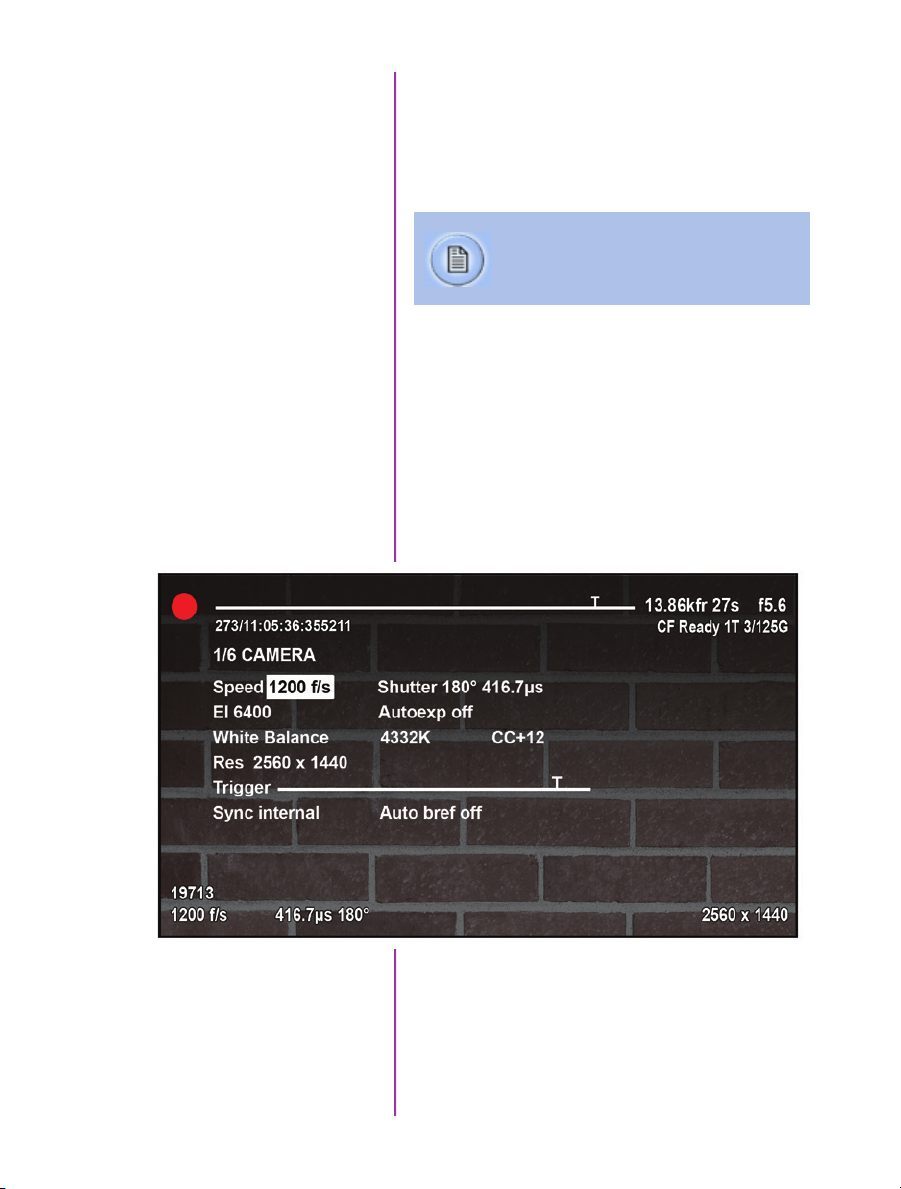
Menu Overview
The VEO-S On-Camera Control menu provides access
to basic and advanced camera settings. The menu is
activated with a press of the menu knob and displayed
through the camera’s video outputs (SDI and HDMI) as
a video overlay, on top of the live image.
The menu is subject to change, and functionality may differ based on camera model and
firmware level.
Navigation
Activate the menu by pressing the menu knob on the back
of the VEO-S camera. Turn the knob to scroll through each
menu item and press to select. The six menu pages can
be quickly jumped between by selecting the page title
(1/6 CAMERA in this example) and scrolling through them.
To exit the menu tap the trigger button. The menu will also
turn itself off after a period of time with no interaction.
menu system
18
Phantom VEO Manual
Six Menu Pages
1/6 CAMERA
2/ 6 IMAGE
3/ 6 SETTINGS
4/ 6 INFO
5/ 6 AUTO
6/ 6 ADVANCED
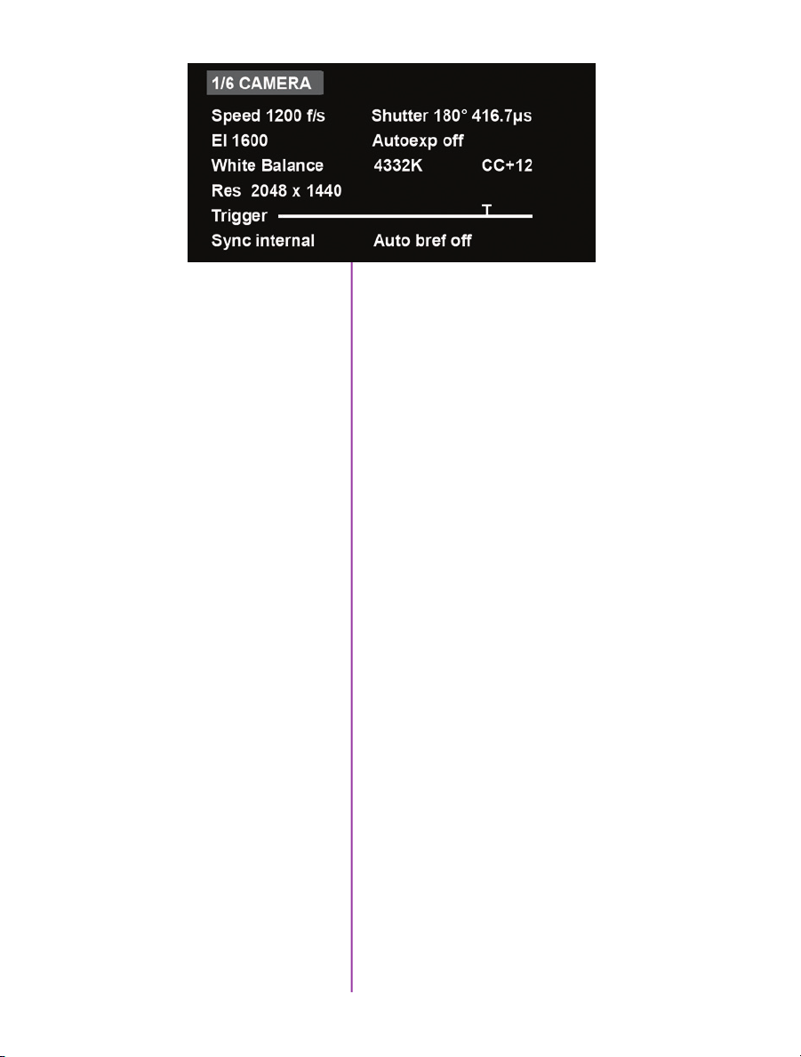
1/6 CAMERA
The CAMERA menu page includes control for the
fundamental settings of a high speed camera.
Speed
Shutter
El
Autoexp
White Balance
Res
Trigger
Sync
Set the acquisition frame rate in frames-per-second.
Set the exposure time, which is displayed in degrees and
time (microseconds in this example).
Set the Exposure Index (EI), also known as the “effective
ISO”. The lowest setting is the base ISO of the camera.
Enable autoexposure, which can be useful in the case of
changing lighting conditions.
For color cameras, set the white balance by placing a
white or neutral gray object in front of the camera. Ensure
that the white subject is not fully saturated. Select the
word ‘White Balance’ and rotate to select “OK”. The color
temperature (K) and color compensation (CC) values can
be further manually adjusted if required.
Set the acquisition resolution of the sensor.
Set the trigger point. The time line represents all frames
available in RAM. Frames before the ‘T’ are pre-trigger
frames and frames after the ‘T’ are post-trigger frames.
Changes the frame sync from internal to an external
source.
Auto bref
When enabled a black reference will be automatically
done every time the camera enters capture mode.
19
Chapter 4: On-Camera Controls

2 /6 IMAGE
The IMAGE page allows for control of image processing
and video settings. These image settings are adjustments
applied to Cine Raw files as metadata. Note: When the
camera is set to a LOG output, these adjustments do not
apply.
Master gamma
Master gain
Master black
PA and PAO
Zoom
Sets the master gamma, which is the relationship between
signal level and brightness output of the image. A linear
gamma would have the value of 1.0. The camera’s default
setting is 2.2 which represents a standard Rec709
gamma curve.
Adjusts the overall signal level of the image. Increasing
Gain will further increase the Exposure Index of the
camera. Vision Research recommends keeping this close
to the default setting of 1 for best image quality.
Adjust the baseline black level. The default of 0 should
produce images with black at 0 on a waveform monitor.
The camera will add a Production Area (PA) with the
specified frame size as an overlay on the video image.
PAO is the Production Area Offset which will move the
Production area from the center of the image both
vertically and horizontally. 0 , 0 is the default.
Change the zoom level of the video output. Fit will scale
a larger or smaller resolution image and optimize it to the
size of the video output. A zoom setting of 1 will show the
image pixel-to-pixel and a setting of 2 will zoom up 2:1.
20
Phantom VEO Manual

Color Bars
Displays SMPTE HD Color bars on video outputs
Video System
Anamorphic
3/6 SETTINGS
Sets the video output to one of the valid video systems.
All the common 720p, 1080p, psf and i settings are
available. The video outputs will change right away,
however the new video system must be confirmed to take
effect. If not confirmed it will switch back to its previous
setting in a few seconds.
VEO4K cameras can output 2.0x or 1.33x de-squeezed
video compensation for anamorphic lenses. 23.98p, 24p,
25p, 29.9p and 30p video systems are supported.
The SETTINGS page allows for user setups to be saved
and recalled.
0-5
Factory Settings
There are six available entries. By selecting one of the
slots users can save or recall that particular set-up to
quickly change all parameters of the camera at a later
date. The values in parentheses are meant as a quick
reminder of camera settings.
Please note that all camera settings, including video
mode, sync mode, image and advanced settings are
included. These settings are saved after the camera
powers down.
Recall the factory defaults to bring the camera back to
the original settings from the last time it left the Vision
Research factory. This includes all capture, calibration,
image processing and video parameters.
This is an important troubleshooting step.
21
Chapter 4: On-Camera Controls

Mode
VEO4K camera models only. This camera can be switched
from Global Shutter to Rolling Shutter. Once the desired
mode is selected, it must be confirmed twice before the
change takes place.
The camera will change modes (the process takes about
20 seconds) and revert to its factory default settings. It is
recommended to use the user setup slots (above) to save
and recall the previous setup to make mode switching
faster.
22
Phantom VEO Manual
4/6 INFO
The INFO page displays unique information of the camera
including:
Model name, memory size and serial number
Firmware level
Current temperature of the Sensor and Camera, and the
power of the Fan and the TEC (thermoelectric cooler) of
the senor. This is for monitoring purposes.
Factory-assigned IP, and optional 10Gb IP address of the
camera
User-defined IP address (secondary IP) which can be
used with an IP range outside of the Phantom 100.100
network. This is set using Phantom PCC software.

5/6 AUTO
The AUTO menu allows for control of some of the
camera’s automatic functions.
Auto trigger
Auto save
From & To
From & To
Enable the camera’s image-based auto-trigger function.
When on, the settings for Speed and Sensitivity determine
the threshold for the trigger’s response time. Vision
Research recommends to experiment with these settings
before determining what works best for your subject.
The settings for Size and Position define the area in which
a change in motion will activate the trigger. A change
outside that window will have no effect.
Auto-trigger is not compatible with VEO4K camera models.
When auto save is enabled, the camera will automatically
save the Cine once triggered to an installed CFast card.
Used to define the first frame and last frame for the auto
save function. By default these are set to the first frame
and last frame of the recorded cine.
When Acquisition Restart is enabled, the camera will
automatically start recording again after the auto-save
or auto-play functions are complete. This is particularly
useful when using multi-cine memory partitions. Be
careful to only use this with auto-save (or auto-play with a
video recorder), and pay attention to remaining space on
the CFast card.
23
Chapter 4: On-Camera Controls

6/ 6 ADVANCED
The ADVANCED page includes settings for either less-used
settings or features which should be used with caution.
R G B Gain, Pedestal
and Gamma
Color Space
OSD On
CF Format
Memory partitions
Set the Red, Green and Blue channels separately for the
Gain, Pedestal and Gamma image processing settings.
These settings can be used with color cameras to fine-tune
the color output. The overall gain, pedestal and gamma
functions can be found on the IMAGE page of the menu.
Rec709 is the standard gamma curve of all Phantom
cameras. The video can switch from Rec709 to Phantom
Log 1 and Log 2 curves. This is useful to see the full
dynamic range of the image over SDI. Log modes will
override all image adjustments including Exposure Index.
Turns off (and on) the On-Screen Display video overlay for
a clean video feed
Erase the entire contents of an installed CFast 2.0
card. VEO cameras employ the NTFS file system. CFast
cards that are currently in a different format will not be
recognized, however they can be formatted for use with
VEO with this function.
Set the amount of partitions to segment the RAM for multicine recording. The RAM is divided evenly, and the same
frame rate and recording parameters will apply for each
partition.
24
Phantom VEO Manual
Frame Burst & Period
Set the number of frames in a burst, which are frames that
captured to RAM with every f-sync pulse. ‘off’ disables
burst mode. The period sets the interval between frames in
a burst (defined in microseconds).
VEO4K camera models are not compatible with burst mode.

Capture a Cine
Capture a Cine file to RAM
1. Ensure camera is in capture mode (trigger button
glows red)
2. Tap the trigger button to trigger the camera once the
event happens. Remember, the position of the trigger
will depend on the post-trigger setting. With a post
trigger set at the end, or ‘0’, the trigger should be
applied after the action occurs.
Enter Playback mode
playback and save
With Cine in RAM, tap the Playback button. The video
output will switch to playback view, where you must
select the Cine for playback. In the case of multi-cine or
partitioned RAM, there will be more than one RAM cine
present, as shown here.
Once the take is selected, there are options to Play,
Delete, Delete all, or go back. Clicking play will close the
menu and the video begins to play forward.
Use the play forward and play backward buttons, and the
menu knob to scrub through the Cine. A long press on the
forward and reverse buttons will start a fast-forward and
fast-reverse playback.
Chapter 4: On-Camera Controls
25
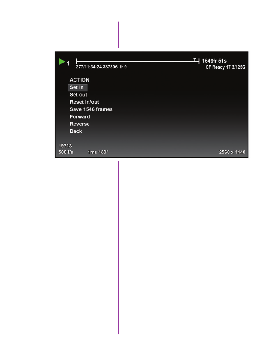
Edit the Cine
Tap the menu knob to further edit and save the Cine to
CFast. An action menu appears with more options.
There are a few ways to go through the playback. A
preferred way is usually to use the scroll knob to go
through the cine.
26
Phantom VEO Manual
Save the Cine
Set an in-point by selecting “Set in”. This will be the first
frame of the cine saved to RAM. Scroll to the last frame
you want to save and select “Set out”.
Now, select “Save” to save the Cine to the CFast 2.0 card.
The OSD will report the save progress with a countdown.
It is important not to interrupt this saving process,
otherwise the card may need to be re-formatted prior
to continued use.
Once saved, the RAM can be cleared and the camera can
go back into Capture mode. The fastest way to do this is
to hold down the trigger button for 4 seconds.
Working with
5
Introduction
Important Workflow Notes
CFast 2.0 Cards
Phantom VEO-S camera models are compatible with
industry standard CFast 2.0 cards. These solid-state
cards are a common form of media for professional video
cameras.
Working with CFast 2.0 cards enables footage to be
quickly transferred from the camera’s RAM to safe,nonvolatile storage which can then be later downloaded using
Phantom PCC software or a CFast 2.0 reader connected
to a PC or Mac. There are several benefits to using these
cards:
• Security. Using CFast is a secure way to get the
recorded Cine Raw files out of volatile RAM.
• Quality. Files saved to CFast cards are always saved
in the Cine Raw format, which maximizes image
quality and workflow options.
• Portability. Using a CFast card means there is no
need to connect the camera to a PC.
A CFast 2.0 card installed in a Phantom VEO camera can
not be used for video playback. Video playback is from
camera RAM only. CFast takes can be reviewed over
Ethernet, in Phantom PCC software.
VEO cameras only support Loop mode recording. Images
must be captured to RAM first, then reviewed and saved
to the CFast card. The transfer rate from RAM to the card
is approximately 90 MB/second.
VEO cameras do not support Run/Stop mode (longer
record times at lower frame rates) like cameras with
CineMag compatibility.
Chapter 5: Working with CFast 2.0
27
Choosing a card
The only requirement is that the card is specified as
“CFast 2.0”. Vision Research has verified various
Angelbird and Lexar branded cards, however any CFast
2.0 is expected to work.
CFast 2.0 Card Format
VEO cameras require the card to be formatted with the
NTFS file system. The NTFS format allows CFast 2.0 cards
to be mounted to a Windows (read/write) or Mac (readonly) without the need for special drivers.
CFast cards purchased from Vision Research will be
pre-formatted, however it is likely that cards purchased
elsewhere will have a different file system. When cards
are in a different file system, the card will show a “CF
Error” on the on-screen display, and PCC software will not
recognize that there is a card installed.
There are three ways to format a CFast 2.0 card:
1. Installed in the camera, using the on-camera control
menu. The camera will count down 3-2-1 and then it
will be ready. It takes a few seconds.
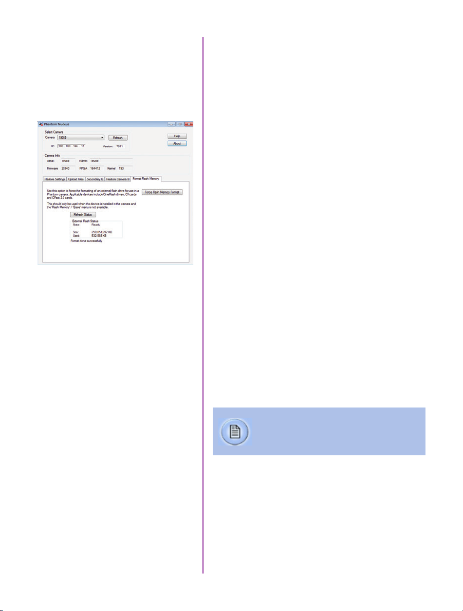
2. Installed in the camera, using the Nucleus utility in
Phantom PCC (pictured at left). The Format Flash
Memory tab and “Force Flash Memory Format”
function should be selected.
3. Installed in a CFast 2.0 reader (typically USB or
Thunderbolt) connected to a Mac or Windows PC,
using the disk format utility. Choose NTFS while
doing the format.
Installing and Removing a
28
Phantom VEO Manual
CFast 2.0 card
Formatting erases all files on the card.
Ensure takes are saved to a secure location
before using any of the format options.
Insert the card into the camera’s CFast card slot on the
rear of VEO-S camera models. The card will be available
immediately, as long as it is formatted NTFS as described
above.
To remove the card, press the plastic lever under the
card slot. Wait approximately 10 seconds before installing
another card. During this time “CF Disconnecting” will
appear on the on-screen display.
Saving to and from
a CFast 2.0 card
First, a Cine must be saved to the RAM of the camera:
Start in capture mode, trigger the camera once the event
happens (depending on the post-trigger position)
Review the Cine in RAM, set in and out points as
described in the previous section, and save to the CFast
2.0 card. Once the card is full, there are two ways to save
the files.
1. Drag and drop the files using a CFast 2.0 card
reader - these are typically available with USB or
Thunderbolt interfaces (or both).
2. Use PCC software to save the files from the card.
The following goes over the PCC procedure:
Saving an Individual Cine
Saving ALL Cine files
Saving Selected Cine files
From the ‘Play’ tab in PCC, select the cine you want to
save from the ‘Cine:’ pull-down menu. You will see all clips
in the RAM as well as the CFast in this list. Once you’ve
selected a clip, you can mark an in and out point if desired
by clicking the ‘[‘ and ‘]’ buttons respectively.
Then click the green ‘Save Cine…’ button. In the ‘Save
Cine’ dialog box, choose ‘Cine Raw’ as the file format,
navigate to the folder where you wish to save the clip and
click ‘Save.’
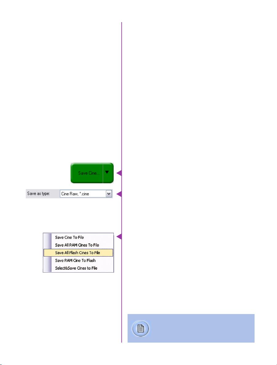
In the Play Tab, click the triangle to the right of the ‘Save
Cine…’ button, and from the popup menu select ‘Save All
Flash Cines To File.’
In the subsequent save dialog window, navigate to the
folder where you wish to save the clips, and select the
‘Cine Raw’ file format. Choose a name for the group of
Cine files and click the ‘Save’ button. Each Cine’s file
name will start with the name you choose, and end with
the cine number.
In the Play Tab, click the triangle to the right of the
‘Save Cine…’ button, and from the popup menu select
‘Select&Save Cines to File.’
“_Flashcine#” will be appended to the file name
of all batch-saved clips, where “#” represents
the number of each take.
Chapter 5: Working with CFast 2.0
29

In the popup window, select the cines you wish to save.
Use the shift key to select a range of clips, or the control
key to add individual clips.
When you’ve selected the cines you want to save,
click “OK.” In the subsequent save dialog, choose the
destination folder and select the Cine Raw file format.
Choose a name for the clips and click the “Save” button.
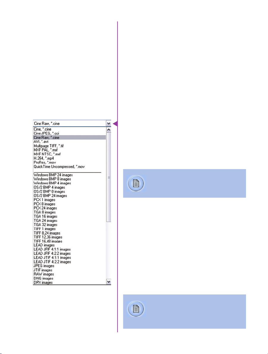
Selecting a file format
(choose Cine Raw)
Erasing a CFast 2.0 card
Vision Research recommends that you save the clips from
a CFast card as Cine Raw files, even though it is possible
to save them in a number of file formats. Cine Raw files
not only preserve all the metadata of the clip (such as
frame rate, shutter speed, timestamps, etc), it is the
fastest and best-quality format. Cine Raw files can easily
be converted to other formats later.
The 10-bit ‘Packed’ format is the default when saving
Cine Raw files. This results in smaller, more manageable
files than the 12-bit ‘unpacked’ format, and with no
quality loss. If you are using 3rd party post production
software to read the Cine Raw files, please ensure they
are compatible with this ‘packed’ format. To save the Cine
Raw in an unpacked format, simply un-check the ‘Packed’
box prior to saving.
A CFast 2.0 card can be erased using the CF Format
function of the VEO menu system, or in Phantom PCC
software. PCC will let you delete individual cines,
otherwise the format will always erase all Cines.
In PCC software, navigate to the “Live>Flash Memory”
menu and click the “Erase” button. Delete individual clips,
delete all, or Format the card. Confirm that you wish to
delete all clips.
30
Phantom VEO Manual
Once complete, all data on the CFast card will be erased,
and the card will be ready for recording again right away.
Phantom PCC
6
Pre-Installation
PCC Application Overview
Software
The latest version of Phantom PCC software can
always be downloaded from the Vision Research
website: www.phantomhighspeed.com/pcc
Phantom control software is certified to operate with the
following Microsoft Windows operating systems: Windows
7 Pro, Windows 8.1 and 10.
The computer and camera must be associated with the
same sub-network to communicate with one another.
Please refer to Chapter 3: Network Settings in this
manual for instructions how to set the Gb Ethernet and/
or 10Gb Ethernet network adapters to communicate with
Phantom cameras.
When multiple computers or network cards are used
together, each port requires a unique IP address, for
example, 100.100.100.1 (255.255.0.0), 100.100.100.2
(255.255.0.0), and so on.
Phantom Camera Control (PCC) software is built around a
multi-layered work area that includes the following work
areas:
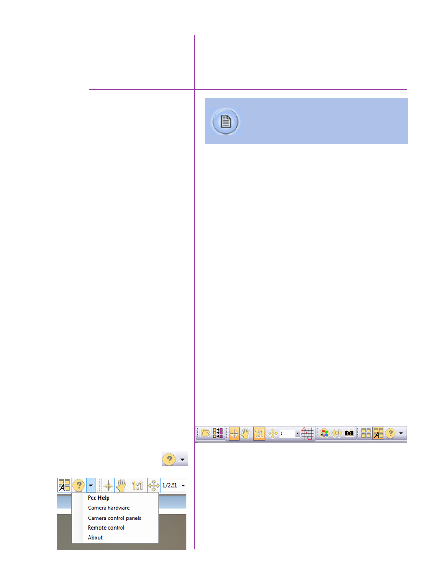
Toolbar
Provides quick access to the most frequently used
functions. Position the mouse over a button and wait for a
second to display a text box describing what it is.
Note the ‘Help’ section. This provides valuable reference
information on the software, including extensive
documentation.
31
Chapter 6: Phantom Software
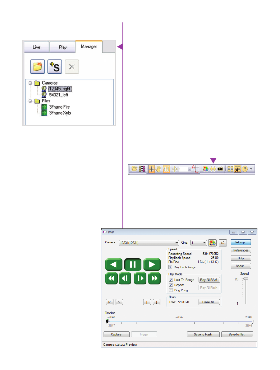
Control Tabs
The main window of PCC is divided into three tabs: Live,
Play and Manager.
When first opened, the ‘Manager’ tab is selected. This is
where connected cameras are displayed, selected for use,
and renamed. It is also used to manage saved Cine files.
To rename, highlight then click the name of a camera.
This can be useful when working with multiple cameras.
All camera control and setting of shooting parameters
(frame rate, shutter, etc.) is performed in the ‘Live’ tab.
The ‘Play’ tab is used to review, edit, and save Cine files,
(either from the camera or from files on the local hard
drive).
PVP (Phantom Video Player)
Application Overview
PVP can be launched directly from the desktop, or by
clicking the ‘Video Out’ toolbar button in PCC.
PVP controls only the camera’s video outputs (HD-SDI
and HDMI) as connected to a compatible monitor.
It provides streamlined control for playback and basic
capture, trigger and save commands.
32
Phantom VEO Manual
PVP provides the ability to view, capture, review, edit, and/
or save a Cine recorded into the camera’s RAM to a hard
drive, or installed CFast card. PVP is extremely effective
when used with high-resolution cameras since most
computers are not powerful enough to view the live or
captured raw files smoothly over Ethernet.
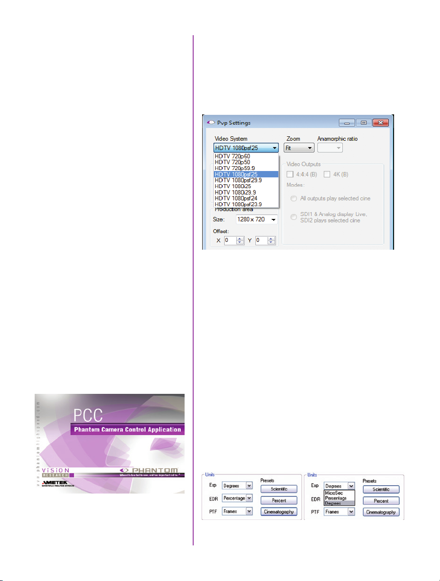
The camera’s video mode and display settings are also
pcc and pvp
set through PVP. The best video system for the camera
or project will vary based on the country you are in, what
kind of video monitor used, and the required display
resolution.
Camera Control via PCC
All available video systems for the connected camera
can be found in the ‘Settings’ menu of PVP along with
production area and other video overlay controls.
The first time PCC is launched it is important to set
up user preferences. PCC provides the ability to select
various units for specific camera parameters by clicking
the ‘Preference’ button at the bottom Manager tab.
Units can be set to commonly used values (‘Presets’) or
they can be customized using the pull-down selections.
First time users should use one of the three ‘Presets’.
33
Chapter 6: Phantom Software
The ‘Exp’ unit is probably the most important unit
to be set. It specifies what unit to use for displaying
the exposure time. This can be displayed in degrees,
microseconds or percentage.
360 degrees = 100% = the maximum exposure time
The other units to set are PTF (Post Trigger Frames) and
EDR which are covered later in this section.
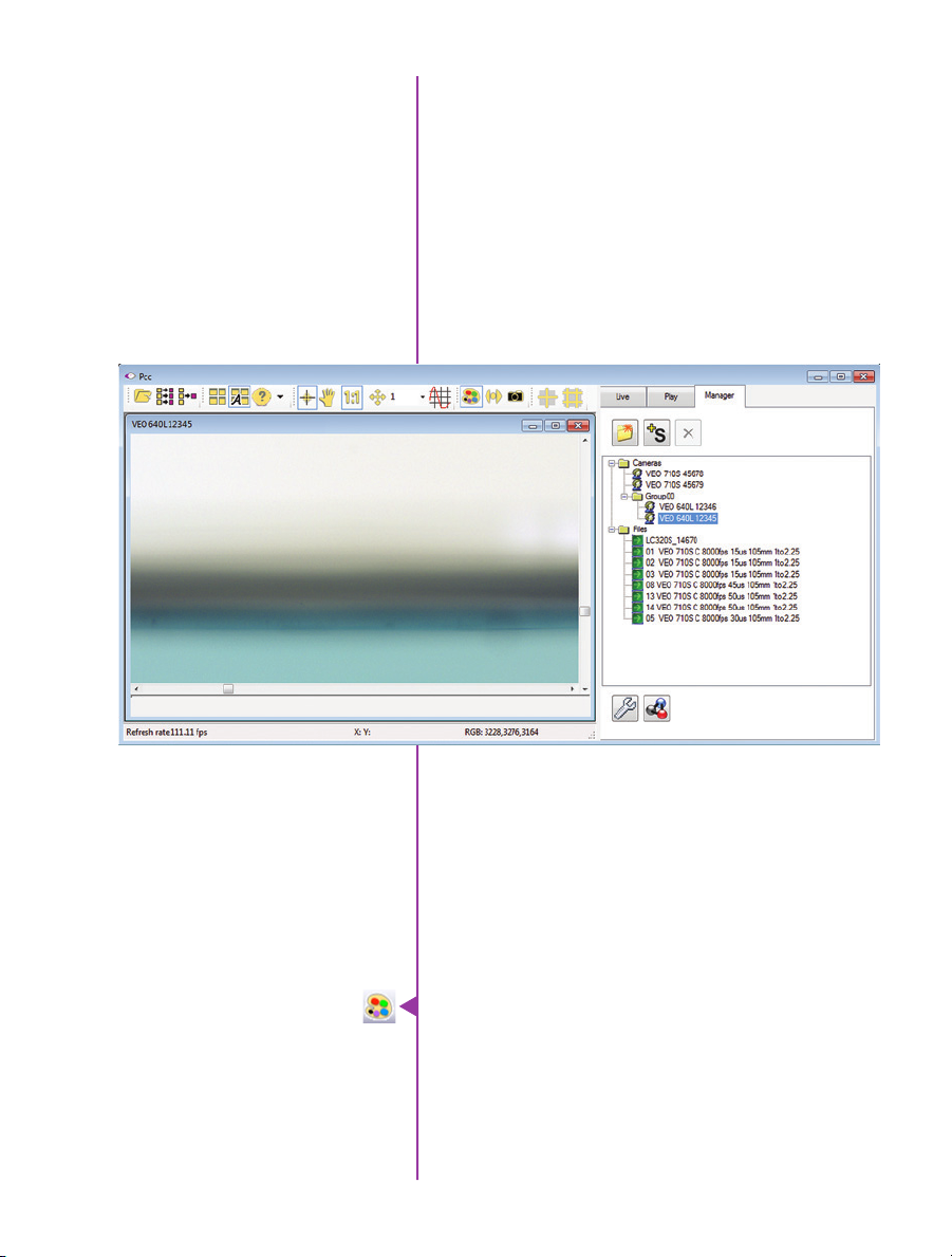
Selecting a Camera
Double-click the camera(s) to be controlled listed in the
‘Manager’ tab, or select the camera(s) from the ‘Camera’
pull-down list in the ‘Live’ tab.
Once a camera is selected a ‘Preview’ panel will display
to the left of the control tabs showing the current
image being captured by the camera. This image may
differ slightly to that of the image being output over the
camera’s 3G HD-SDI port due to display differences in the
video monitor and computer screens.
34
Phantom VEO Manual
Image Processing
Image Tools provides extensive controls over the look of
the image, from color and contrast settings, to image
orientation and crop settings. The menu is accessed by
clicking on the ‘Image Tools’ toolbar button (the one that
looks like an artist’s palette).
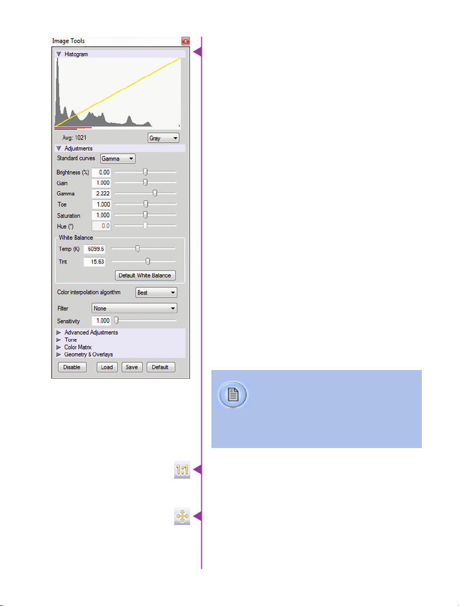
The top of the ‘Image Tools’ window displays a
‘Histogram’. This is a graphic representation of the
pixel brightness levels of the displayed image. The left
represents black, the right represents white and the
height represents the proportionate number of pixels at
that particular value. Unlike a waveform, the histogram’s
shape is not representative of the content - it is simply an
averaging of the brightness values.
Below the histogram are controls which change image
settings of the live images, recorded images and the video
output of the camera.
Some of the variables include; brightness, gain, gamma,
saturation, hue, white balance adjustments (Temp (K) and
Tint), individual red, green and blue pedestal, gain and
gamma values, tone control, and more.
At the bottom of the window is a ‘Default’ button that
restores all parameters except white balance, tone, and
color matrix to their default values.
The ‘Default White Balance’ button restores white balance
to the factory defaults on color cameras.
The Tone ‘Reset’ button restores the image tone to the
default values, and the Color Matrix ‘Restore’ button return
the color matrix values to their default values.
Changes made here only affect the meta
data of the Cine raw file. They are applied in
software, but not “baked in.” If you are saving
to a different format or recording the video
output ensure everything is set to values that
produce the image you wish to record.
The ‘Zoom Actual Size’ toolbar button resizes the images
being displayed in the Preview/Playback panel to their
actual size.
The ‘Zoom Fit’ toolbar button resizes the images to
fit panel. Images can also be zoomed to a specific
magnification ratio by selecting a number from the pulldown list to right of the Zoom Fit button.
Chapter 6: Phantom Software
35

Automatic White Balance
Performing a White Balance should be the first step
in color adjustment (White Balance not applicable to
monochrome cameras).
Right click on an area that resembles white in the image
in the ‘Preview’ or Playback’ panel, then click on the
‘White Balance’ pop-up window. It is not necessary to fill
the frame with white – a small target can be used.
It is recommended to perform the White Balance after
a CSR and on a white or gray object that is not fully
saturated.
36
Phantom VEO Manual
Capture Setup
Just below the ‘Camera’ selector in the ‘Live’ tab are a
series of expandable headers, which contain groups of
related camera settings.
This manual covers the most commonly used
settings, see the ‘PCC Help’ file for details of
other settings.
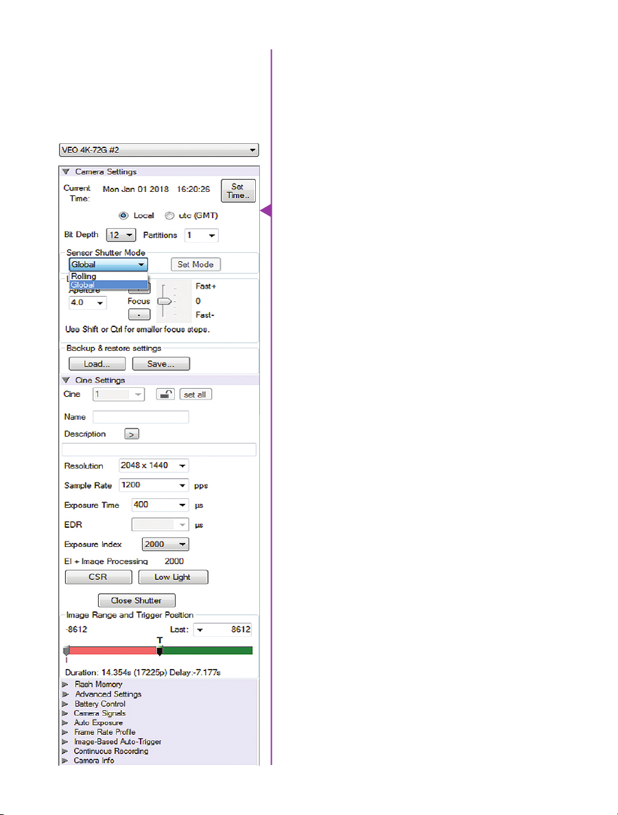
Camera Settings
& Cine Settings
Set Time: Synchronizes the time stamps embedded in the
recorded image data to the computer’s clock.
Bit Depth: VEO cameras operate in 12-bit mode only.
Shutter Mode: For VEO4K models only. Switch the camera
between operating with a Global or Rolling Shutter. Once
set, click ‘OK’ to confirm. See FAQ on this topic for more
information.
Partitions: Select the number of desired partitions (evenly
divided memory segments) from the ‘Partitions’ pull-down
menu. For basic camera setups, this should be set to one.
Lens Control: Available for Canon EF lenses only, for
control of aperture and focus.
Backup & Restore: Allows for user and factory settings to
be saved and recalled from the camera’s memory.
Resolution: Set the camera’s acquisition resolution. There
are several options in the pull-down menu, alternatively
type in a value and the closest valid resolution will be set.
Sample Rate: Set the acquisition frame rate in framesper-second (FPS).
Exposure Time (shutter): Set the exposure time in degrees,
microseconds, or percentage (this depends on how the
PCC preferences are set).
EDR (Extreme Dynamic Range): Set a secondary exposure
time to pixels that may become fully saturated or
overexposed. This is valuable for monochrome cameras,
but be careful with color cameras as a color cast will
occur on the areas of the image which EDR is applied.
VEO4K models are not compatible with EDR.
Exposure Index: Set the exposure index (Effective ISO)
of the image, by loading preset tone curves. Adjusting
gamma, gain and other settings will contribute to the
overall EI value, and this combined value is what should
be used to determine lighting.
CSR (Current Session Reference): Closes the camera’s
internal shutter and resets the black point of every pixel
for optimal image quality.
Chapter 6: Phantom Software
37

Image Range and Trigger Position: The slider represents
the memory buffer, with the ‘Duration’ indicated in
seconds and the total number of frames available.
The trigger position is indicated in the ‘Last’ pull-down
menu and as the ‘T’ slider along the timeline. The trigger
position is exactly when the trigger signal will be detected
in the Cine.
Key Advanced Settings
The first of these key features is the option to enable
the ‘Start/End of recording actions’ to be performed
automatically at the beginning or end of a shot. The most
common ones are:
• ‘Auto save to CineFlash/CardFlash’ this feature saves
a user-specified portion of a clip to the CFast card
immediately after recording.
• ‘Auto play Video Out’ begins playback after record-
ing. The range marked under ‘Auto play Video Out’
affects both playback and saving to the CFast 2.0
card.
• ‘Restart Recording,’ when enabled, automatically
restarts the recording process after the ‘Auto’
actions have been performed.
When ‘Restart Recording’ is enabled PCC does
not provide any user confirmation before the clip
is erased from RAM and starts recording again.
This feature should be used with care!
‘External Sync’ instructs the camera to utilize one of the
following three frame sync clock sources:
• Internal - The camera uses its internal crystal
oscillator to drive the camera’s frame rate.
• External - should be selected when an externally
supplied frame sync clock pulse is supplied to drive
the frame rate. This can be used to synchronize two
cameras together via F-Sync.
38
Phantom VEO Manual

• IRIG - should be selected when an IRIG-B signal is
supplied to drive the camera’s frame rate. When
using IRIG, frame rate can only be set in multiples of
100.
• LockToVideo - Frame rate is driven by the camera’s
current video rate. FPS will jump to the closest
multiple of the current video rate (23.98, 24, 25,
29.97 or 30).
Flash Memory
Recording a Cine
Triggering the Camera
Displays the amount of ‘Free’ space and size (in Gigabytes) of an installed CFast card. Direct recording is not an
option for VEO cameras. By clicking ‘Erase’ a secondary
menu pops up which allows you to delete individual files
or format the card.
To begin recording to the camera’s RAM click the red
‘Capture’ button.
The red ‘Capture’ button changes to ‘Abort Recording’ and
the green ‘Trigger’ button is enabled when the camera is
recording. The Abort Recording button instructs the camera to stop recording, leaving the camera’s RAM empty.
Selecting the ‘Trigger’ button instructs the camera to
immediately stop recording when the ‘Trigger Position’ is
set to zero. If a value greater than zero is set, the camera
will continue to record ‘post-trigger’ frames until the
user-specified value is met.
If a clip exists in the camera’s memory, you will
be asked if you are sure you wish to delete it
before continuing. If yes, click ‘Delete cine(s)
and start new recording’.
For a precise trigger timing use the trigger button on the camera body or an external switch
connected to the trigger input.
Chapter 6: Phantom Software
39

Reviewing a Cine
A
B
Once the camera has completed recording a Cine in the
camera’s RAM it can be reviewed by selecting it from the
‘Cine’ pull-down selection list in the PCC ‘Play’ tab.
A previously saved Cine stored on the
computer’s hard drive can be opened using
the ‘Open File’ toolbar button (This also places
the file under the ‘Cines’ group folder in the
Manager tab).
Playback options can be changed via the ‘Play Speed &
Options’ and the Cines’ metadata can be viewed in the
‘Frame Info’ and ‘Cine Info’ sections.
Use the ‘Video Control’ buttons to review the cine.
C
A Reverse Play
B Pause
C Play
D Fast Reverse
E Reverse 1-Frame
Performing a Quick Search
40
Phantom VEO Manual
E
D
F G
F Advance 1-Frame
G Fast Forward
Through a Cine
Quickly search through cine file to find the points of
interest:
‘Scroll’ (scrub) through the clip using the ‘Image Location’
slider or click anywhere on the timeline to jump to points
in the cine quickly.
‘Jump’ to the trigger frame by clicking on the ‘T’ button,
or jump to specific frames by entering the frame number
into the jump “#” data entry field, then hit the enter key.
‘Image Search’. The goal is to search or find an image
change in the recording, based on the difference between
image content. Right-Click on the ‘Play’ button to begin
the image search. Besides image content changes, Image
Search can also look for images that are tagged as ‘Event’
images.

Editing a Cine
Using the following ‘Video Control’ buttons locate the first
image of the cine to be saved and click the ‘Mark-In’
button.
Locate the last image of the cine to be saved and click the
‘Mark-Out’ button.
Click ‘Play, Speed, & Options” and enable (check) ‘Limit to
Range’.
Under the ‘Video Control’ buttons click the ‘Jump to Start’
button, then review the edited cine.
Saving a Cine
Working with Cine files
Click the ‘Save Cine...’ button to save the edited cine to
the computer’s hard drive.
If you wish to save the clip to a CFast 2.0 card, click the
down-arrow to the right of the ‘Save Cine...’ button and
select ‘Save RAM Cine to Flash’.
The images recorded on the camera’s RAM or CFast
card are stored in a Vision Research proprietary RAW
(uncompressed) file structure called a ‘Cine’ file.
These Cine files can be converted to industry standard
formats (ProRes, H264, DPX, DNG, TIFF, JPEG, and more)
with PCC software provided by Vision Research.
Phantom PCC and PVP software are only compatible with
Windows operating systems, however there are third party
solutions available for working with Phantom cameras in
Mac OSX.
Glue Tools™ offers the most versatile solution, called the
‘Phantom Cine Toolkit’. The Toolkit allows for cine raw files
to be viewed on the Mac in a quicktime .mov wrapper.
This enables many popular editing programs to work with
cine files, such as Final Cut Pro and Avid Media Composer.
41
Chapter 6: Phantom Software
Compatibility with Video
Editing Programs
Several popular video editing programs, such as DaVinci
Resolve and Adobe Premiere, have incorporated the
Phantom Cine Raw file format into their software. This
means Cine files do not have to be converted and no
additional software is required.
Please test the footage with the program you choose
before committing, as updates to the program or Cine file
format can sometimes break compatibility. For this reason,
it is important to know how to properly convert Cine Raw
files using PCC.
Converting Cine Raw Files
Single cine files can be converted by selecting the desired
format from the ‘Save as Type’ selection list in the ‘Save
Cine’ dialogue window.
The file formats above the separator line in the ‘Save as
Type’ selection list are ‘movie-like’ formats (meaning the
entire clip will be saved as a single file) while the formats
below the line are image formats (meaning each frame of
cine will be saved as a sequence of images.
Re-saving a clip in the ‘Cine RAW’ format
can be useful for creating sub-clips with no
loss in image quality or metadata.
To convert a cine to a ‘movie-like’ format select the
desired format from the list, navigate to the destination
folder, assign a file name to the clip and save.
Some valuable parameters can be found in the ‘advanced
settings’ window, such as the particular codec. In the case
of ProRes, the default is 4:2:2 HQ, however other options
are available.
Other formats, like .avi and .mp4 allow the compression
ratio to be entered. The lowest compression (highest
quality) is the default.
42
Phantom VEO Manual
Ensure all image adjustments have been
applied prior to initiating the conversion
process. All metadata will be embedded into
the converted images.
Converting to a Series
or Stack of Images
To convert a cine clip into a sequence of images (frames)
you must add one of the following annotations to the end
of the file name: ‘!n’ or ‘+n (where n is a number between
1 to 8, corresponding to the Cine’s frame count). If a cine
has up to 999 frames, the number 3 can be used. If it
has 9999 frames then 4 can be used. This will assign the
sequential frame numbers to the file name for each new
image.
Example: image_!5.tif
The ‘!’ annotator instructs the software to append the
cine’s image number (relative to the trigger point) to the
file name. If the first frame in the clip is - 100, then the
first converted frame will have the name: image_-00100.
tif.
The ‘+’ annotator adds frame numbers starting from 1.
Example: image_+5.tif
This will cause the first converted frame to have the name:
image_00001.tif
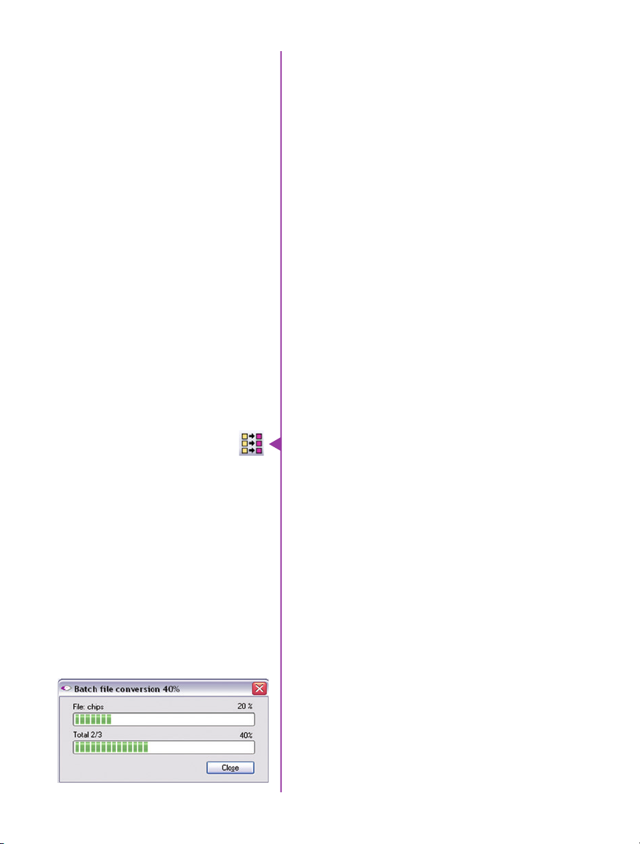
Batch Convert
file conversion
The ‘Batch Convert Files’ toolbar button can be used
to convert multiple saved cine files into any one of the
supported file formats. Use the shift and/or control keys to
select the cine files you wish to convert in the ‘Open Cine’
dialogue window, then click the ‘Open’ button.
Navigate to the destination folder and select the file
format. The ‘File Name’ will depend on the type of file
format you are converting to.
If you are converting the cine file into a ‘movie-like’
formats leave the file name as ‘All selected file.’ The
software automatically assigns the original file name to
the converted file.
If converting each Cine into a sequence of images, then
the ‘+’ or ‘!’ annotators must be used, followed by the
specified number (example: image_+5)
PCC creates a separate folder for each file, assigns the
original file name and appends the appropriate image
number and extension to each image.
Once the ‘Convert’ button is clicked a progress window
appears for the duration of the conversion process.
Chapter 6: Phantom Software
43
44
Phantom VEO Manual

Programmable I/O
7
“Programmable” vs
“Assignable”
Phantom VEO and
Programmable I/O
Signal Architecture
Phantom cameras have long employed the use of Auxiliary
ports where one BNC port, whether on the camera body,
capture cable or break-out box, can be assigned to one
of a few different signals. This has been necessary due
to an increasing number of signals and a limited amount
of physical space on the camera and pins on the capture
connector.
On those cameras the port is labeled “Aux” and the
‘Camera Signals’ menu in PCC is used to select the
signal. This feature can be referred to as “Assignable” I/O.
With the introduction of the Phantom VEO the camera
incorporates a pulse processor, which contributes to
a new powerful feature called “Programmable I/O”. In
addition to assigning different signals, now the signal
characteristics can be modified to interface with external
devices not before possible.
In most cases the signal polarity, filter time, delay, pulse
width and edge (rising vs falling) can be set. Setting these
characteristics is referred to as “pulse processor control”.
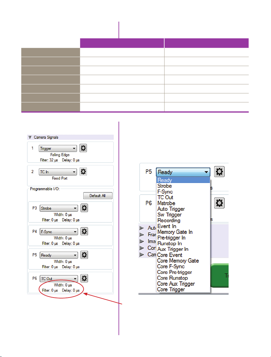
Programmable I/O ports can be identified on the camera
body with a ‘/P’. Both models have a fixed trigger
and Timecode-in port, and then VEO S-models have
four Programmable I/O ports (P3, P4, P5 and P6) and
L-models have two (P3 and P5)
Each port is to be identified in the PCC ‘Camera Signals’
menu by using the port number. Each Programmable I/O
signal has a default which will be set after a factory reset
or by using the “signal defaults” function in PCC.
Chapter 7: Programmable I/O Signal Architecture
45
VEO Signals with Default
Assignments
Port 1
Port 2
Port 3 (P3)
Port 4 (P4)
Port 5 (P5)
Port 6 (P6)
Range Data
VEO L-models VEO S-models
Trigger (fixed) Trigger (fixed)
Timecode-in (fixed) Timecode-in (fixed)
Prog I/O - Default: F-Sync Prog I/O - Default: Strobe
N/A Prog I/O - Default: F-Sync
Prog I/O - Default: Strobe Prog I/O - Default: Ready
N/A Prog I/O - Default: Timecode out
None Yes, dedicated Fischer port
PCC interface
Beginning with Phantom PCC 2.8 the Camera Signals
menu, located in the Live Tab, provides access to and
control over these Programmable I/O signals. All listed
signals are not necessarily active with VEO, including
Runstop and Mstrobe.
46
Phantom VEO Manual
A summary of the current signal settings is found under
the pull-down associated with each port. By clicking
“Default All” PCC will re-assign the factory-assigned
defaults for the Programmable I/O signals.

Pulse Processor Control
After selecting the signal assignment, further configuration
is possible by clicking the gear symbol next to each port.
The Pulse Control menu is opened, as shown below.
A graphic representation of the signal behavior is also
displayed, however this is not to scale and should just
be used as a reference. Use of this feature requires
an oscilloscope to truly visualize the signals and the
subsequent changes with each adjustment.
Summary of Pulse
Processor Settings
*Input: When a signal is generated
by the camera it serves as an input
to the “pulse processor”, so in this
context the term ‘input’ does
not represent an externally
generated signal.
Invert: Inverts the signal at the output of the pulse
processor.
Falling: Selects ‘Falling Edge’ mode for the pulse
processor. This mode is only relevant if the ‘Width’ is also
specified. When the ‘Falling’ token is present together
with ‘Width’, the pulse processor will generate a negative
pulse, triggered from the negative edge of the input signal.
Delay: Delays the output pulse by the specified time in ms,
μs, ns or camera clock multiples. If the ‘Width’ token is
not present, both edges of the signal are delayed by the
same amount. If present, the delay is measured from the
rising edge of the input* signal unless the ‘Falling’ token
is present, in which case the delay is measured from
the falling edge of the ‘input’. The delay time is specified
in microseconds (as a floating point number), and is
internally converted and rounded to pixel clock units.
Chapter 7: Programmable I/O Signal Architecture
47

Pulse Processor
Settings (cntd.)
Width (Pulse Width): When a ‘Width’ token is present, a
defined-length pulse is generated, which starts after the
specified ‘Delay’, after the active edge of the ‘input’ signal.
The length of the pulse is specified in microseconds
(as a floating point number) and internally converted to
pixel clock units. The maximum pulse width is at least
10 seconds. However, if the period of the ‘input’ signal
is lower than the selected width, the latter is dynamically
clamped to the signal period. The minimum pulse width is
one pixel clock.
Filter (Filter Time): When a filter token is present, the ‘input’
of the pulse processor is filtered through an edge filter of
the specified time. The time of the filter can be between
0 and 1 second. In order for the output of the filter to
be asserted, the ‘input’ signal must be continuously
asserted for the specified duration. In order for the output
of the filter to be de-asserted, the ‘input’ signal must
be continuously de-asserted for the same duration. The
edges of the ‘input’ are thus delayed by the specified
filter time (for a ‘clean’ input pulse). Filtering is applied
before and independently of the delay and duration. The
filter time is specified in microseconds (as a floating point
number), and is internally converted and rounded to pixel
clock units.
programmable i/o
48
Phantom VEO Manual
Pixel Clock
Programmable Signals
and Descriptions
The period of the pixel clock is the basic time interval for
all camera timing.
Please note that pulse processors can sometimes
generate pulses that are too short for the output drivers to
switch properly, and as such the processed signal should
be verified with an oscilloscope before use.
Ready: An isolated open collector output with 1k pull-up
signal (active high). Ready is asserted when the camera
goes into capture mode and is de-asserted either when
the Cine is triggered, or when the Cine recording is
completed. Ready changes synchronously with frame
capture (at the end of each exposure), so in external sync
mode it will not change until F-Sync pulses are received.
Strobe: An isolated open collector output signal, with 1k
pull-up. When asserted (low) Strobe indicates that the
camera integrates (the electronic shutter is open). Strobe
is low for the duration of the exposure.

Programmable Signals
and Descriptions (cntd.)
Note: All descriptions are the
signal’s default state prior to
processing.
F-Sync: Is the only signal which can be set as an output
or input. By default it is output (sync-internal). Output
signal is a frame sync pulse from the camera’s frame rate
generator. A short (few hundred ns depending on camera
model) negative pulse, with the falling edge used as timing
reference. Input signal is active on falling edge (default
state is high).
TC Out: A positive polarity time code signal. Normally
an unmodulated (dc-shifted) IRIG-B (at RS-232 levels),
which follows the internal time base of the camera. It
is recommended not to process the TC-Out, since a
processed signal may no longer represent a standard or
accurate time code.
Auto Trigger: Used to output a hardware trigger signal or
pulse with the duration.
Software Trigger: An active high output signal (pulse)
generated as a result of the trigger protocol command.
Recording: An active high output signal. When active,
indicates the camera is recording into a RAM partition.
Event In: If the input is sampled low at the end of an
exposure, an ’E’ (Event) bit in the frame’s time stamp is
set.
Memory Gate In: If the input is sampled low at the end
of an exposure, the corresponding frame is skipped from
storage to RAM.
Pre-trigger: An active low input (default high) signal.
Keeping this signal low for enough time (10-500ms, or
until the ‘Ready’ signal goes high) will make the camera
start recording if it has an available RAM partition.
Aux Trigger: An input signal active on rising edge
(default high). This is an alternative trigger input that
can be processed through the programmable port pulse
processors and assigned to different ports.
Chapter 7: Programmable I/O Signal Architecture
49

Programmable Signals
and Descriptions:
The Core Signals
core signals
Core signals are copies of externally generated signals,
routed through the camera and output to assigned ports.
Core signals can be pulse-processed before being output.
The current list of signals is:
Core Event: Feedback output from the Event In signal. The
feedback is taken after any pulse processor for the input.
Core Memory Gate: Feedback output from the Memory
Gate In signal. The feedback is taken after any pulse
processor for the input.
Core Frame Sync: Feedback output from the F-Sync In
input. The feedback is taken after any pulse processor for
the input, but before the delay element.
Core Pretrigger: Feedback output from the Pre-Trigger
signal. The feedback is taken after any pulse processor for
the input.
Core Auxtrigger: Feedback output from the Aux Tigger In
signal. The feedback is taken after any pulse processor for
the input.
Core Trigger: Feedback output from the main Trigger input.
The feedback is taken before the trigger signal is affected
by the trigger polarity, filter or delay settings. “Core
Trigger” can be used like a “Trigger Out” signal.
50
Phantom VEO Manual

8
Measurements
Introduction
Units of Measurement
Included in PCC software is a set of 2D motion analysis
tools which go a step beyond the visual when it comes to
providing valuable data about the subject. Analysts can
perform timing, position, distance, velocity, angle and
angular speed measurements as well as track multiple
points to compute and graph in their XY-coordinates,
speed or acceleration. The interface can also harmonize
this measured data with images.
This section reviews various PCC measurement
capabilities. Further documentation, including Step-byStep procedures can be found in the PCC help
documentation available within the software.
Units of Measurement specify the computing and
reporting unit for distance, speed, acceleration, angle
and angular speed measurements. Establishing a
measurement scale is an important first step to using the
measurement functions.
Define the Measurement Units in the Preferences menu,
accessible by clicking the wrench icon from the Manager
tab.
PCC display automatically tracks golf club head to calculate swing speed, path and acceleration.
51
Chapter 8: Measurements

“Other options” in Measurement Preferences:
Unique Scale per Application: When enabled the same
scale will be applied to all subsequently opened Cines.
Auto Advance to Next Image during Collect Points: the
Cine advances to the next image automatically once
all the collect points have been manually specified on
the displayed image. This option should be disabled
(unchecked) if auto tracking points is to be used.
Auto Update Graphics During Collect Points: A graphical
display of the tracked points will overlay the images during
the collect point process.
Measurement Tab
PCC’s measurement functions are found in the Play tab
and will work with saved files (Cine Raw or converted files)
or directly from the camera’s RAM playback.
To define a measurement scale, the first step is to use the
‘Calibrate’ function in the image with a known scale, then
specify that scale size. Once created all measurements
are computed and displayed using the scale unit.
Coordinate measurements are calculated from an origin
point pixel. By default this is the top-left corner of the
image however it can be changed when performing
measurements. Each coordinate consists of 2 numbers
(x,y) indicating the position of a pixel in the image on the
two-dimensional plane from the origin point.
Your choice of origin will be largely dependent on the
subject and the type of motion being studied.
The ‘Default Origin’ and ‘Set Origin’ buttons will
be disabled if any of the ‘Instant Measurement’
or ‘Collect Points’ options are active.
Once the origin point is set, activate ‘Instant
Measurements’ and select one of the available options for
Distance, Angle and Speed or Angle and Angular Speed.
52
Phantom VEO Manual
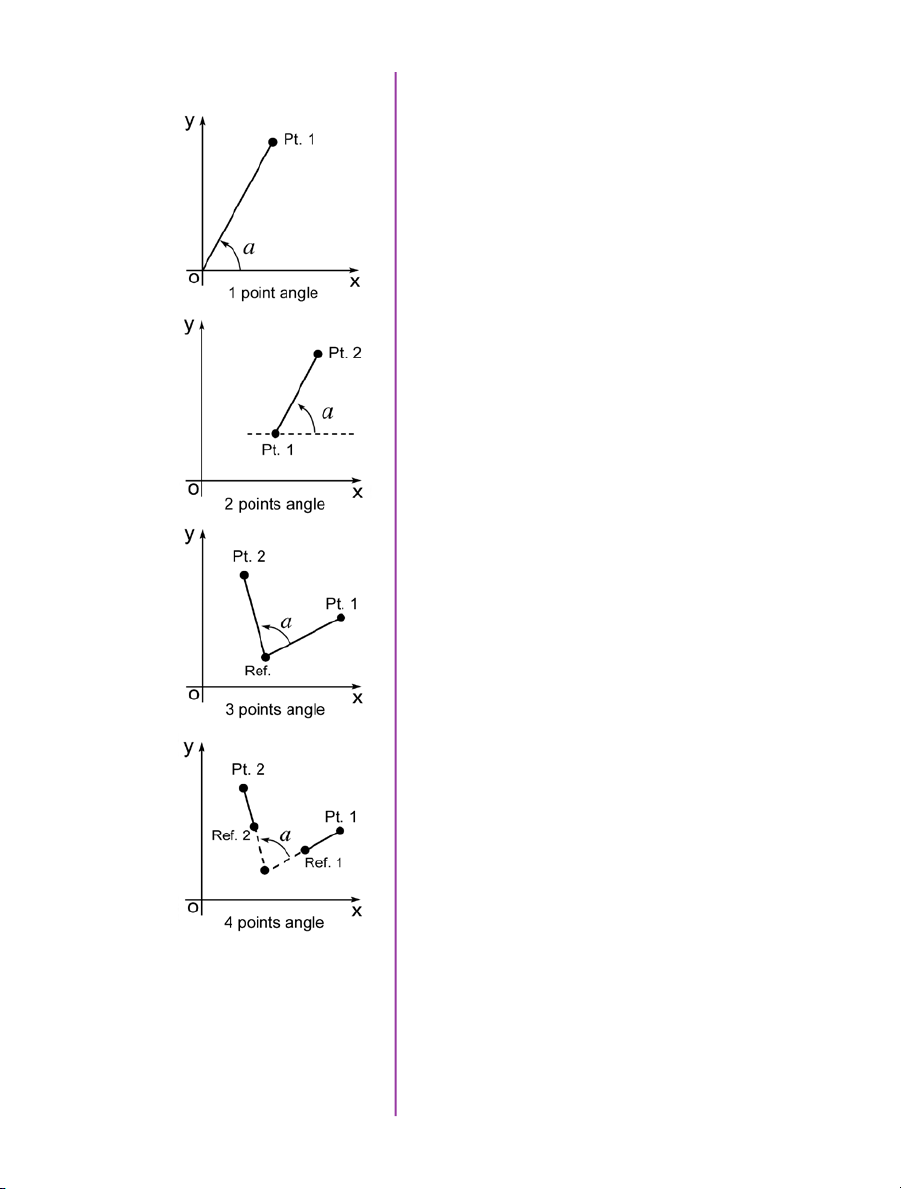
Instant Measurements
Instant Measurements consists of four unique motion
analysis tasks, including:
1. Distance & Angle & Speed: Origin + 1Point. Used to
measure the distance and speed of linear motions
with respect to a fixed point of origin, the angle
formed with respect to the x-axis, or the speed of
a rotational motion (computed with respect to the
horizontal axis of the picture screen), when only one
point is known.
2. Distance & Angle & Speed: 2Points. Used to
measure the dimensions of an object or space, the
displacement and speed of an object in one image
with respect to its new position in any subsequent
image, angular speed (computed with respect to a
horizontal axis), or the speed of a rotational motion
when two points are known.
3. Angle & Angular Speed: 3Points. Used to measure
angles when the vertex and the two end points of the
angle are visible.
4. Angle & Angular Speed: 4Points. Used when the
vertex or the center point of rotation is unknown or
lay outside the image area, the angular speed can be
found by comparing the position of an object in one
image to its position in the next image.
Collect Points
Each of these are calculated by selecting a point (or
points) in one frame, then forwarding the video and
selecting the same point (or points) in the subsequent
frame. Results are posted in the ‘Results’ area.
All Instant Measurements can be used in conjunction
with a Report File or without. With a report file opened,
the image number, elapsed time from trigger, unit of
measurement, distance, dimension, speed and comments
are automatically saved in the file.
Point data (for up to 99 points-per-image) can be
collected, tracked within PCC software and imported by
third party programs. This feature creates a separate data
file for point coordinates, speed and / or acceleration.
53
Chapter 8: Measurements

Collect Point Data
for Tracking
The point data can be collected two ways:
1. Manual Track. Used to track point positions
(coordinates) from one image to the next once its
starting point is defined.
2. Auto Track. Used to track point positions from one
image to the next once its starting point is defined.
Auto Tracking is done during the play of the Cine (step
forward, step backward, play forward, play reverse). It is
very important that the images be in succession; Auto
tracking will self-disable if they are not. To avoid this from
occurring ‘Play Speed & Options>Play each image’ is
forced on. It will also disable itself when jumping from
the last image to the first. However, the points will remain
attached to those areas in the image as they are stored
in the user-specified ‘.ppf’ (pictures-per-frame) file. This
allows the end-user to reopened Cine and / or picturesper-frame file to overlay the points, or export the file to a
spreadsheet.
54
Phantom VEO Manual
Autotracking,
Step-by-Step
After the measurement units, calibration scale, and origin
point have been defined:
1. Locate the first frame with the points to be tracked.
2. Create a .ppf (picture-per-frame) file by clicking the
‘...’ button near the ‘File path’ box under ‘Collect
Points’
3. Navigate to the folder to save the ‘.ppf’ file; enter a
name and click on the ‘Open’ button.
4. Specify the number of points to be collected (tracked)
in the ‘PPF’ field (99 maximum).
5. Enable the ‘Active’ enable box.
6. Click the center of the point(s) to be tracked. Ideally,
the selected points should be a small target or the
edge of an object that will be in motion. Do this until
all points have been manually specified. If the ‘Auto
Advance to Next Image During Collect Points’ has not
been enabled in the ‘Preferences>Measurement tab
you will need to advance the file to the next image.

Define Point Parameters
Once the points are selected, click the ‘Current Point/
Options’ button to further define each point:
Autotrack Active - turns on and off the autotracking of the
selected point.
Show Rectangles - displays the ‘Target Area’ and ‘Search
Area’ rectangles for the point. The region sizes are
defined by the ‘Template Area Size’ and ‘Search Area Size’
parameters.
Draw Point Trajectory - turns on and off the ability to graph
and display the path over the image area.
Template Area Size - defines the width and height (in
pixels) of the of the ‘Template Image’ to search for and
track. The center of the ‘Template Image’ was determined
when the point was specified.
Search Area Size - defines how large of an area in relation
to the ‘Template Area’ to search, in the next image, for
point matches. A value equal to the ‘Template Area Size’
indicates that the tracking algorithm should search in a
region the same size. Larger values will result in larger
search areas, which will take a longer time to search.
Typically these values are set to 2-3 times the size of the
initial image template.
Points used for autotracking can
be dedicated markers (crosses,
quarter of circles in opposition
black-white, white-black) or
any objects in image that has
something different on two
orthogonal directions. The middle
of a straight line is not good but
an isolated spot, such as the end
of a line or a corner are okay.
Tracking Sensitivity - defines the acceptable level of
difference between the template and the occurrence in the
new image. A strict matching algorithm is used to avoid
false matches; however this may lead to more frequent
loss of targets during tracking. To compensate for this, you
can adjust the ‘Tracking Sensitivity’ to be more tolerant.
Template Image - displays an image of the point used for
tracking.
Set to All Points Button - used to apply the above settings
to all currently defined points.
55
Chapter 8: Measurements

Once point settings are defined, enable ‘Autotracking’
to turn the feature on. In the event a ‘Template Image’
(tracking point) can not be tracked or is lost the
‘Autotracking’ feature will disable itself.
Optionally, enable (check) ‘Update Template’ to update
(change) the ‘Template Image’ to the image (point)
presently marked by the ‘Template Area Size’ rectangle.
Due to rotations, shadows, etc. the point can be lost. If
‘Auto update’ is enabled, PCC will attempt to restrict the
selective disabling of the feature.
Graphics
Optionally, click the ‘Graphics’ toolbar button to view
a chart of the tracked points. This opens a graphical
interface (displayed to the right of the Cine image). It is
used to display signal acquisition information or position/
speed/acceleration and the coordinate X or Y of tracked
collect points. The displayed values take into account
the global measurement preferences for position/speed/
acceleration. Only windows for the type of signals that are
present in the .Cine file will be available.
56
Phantom VEO Manual
Finishing Steps
1. Deactivate (un-check) Collect Points.
2. Click the ‘Save’ button to save the completed points
and computation files that are required.

9
Accessories
Introduction
Cameo Accessories
for Phantom VEO
Phantom VEO cameras ship with a basic set of all that is
needed to get started using the camera, including a power
supply, Ethernet cable, SDI cable and PCC software.
Vision Research offers several accessories meant to
facilitate the use of the VEO for different applications, as
the size and shape of the camera make it particularly well
suited for different rigging options.
This section includes a list of some of those key accessories.
Check with your sales representative if you do not find
what you are looking for here and for pricing info.
Note the VEO is identical on the top, bottom and right side
when it comes to mounting points, so these can be attached
to any of those surfaces. This allows the same mounting
possibilities when using the camera vertically, for example,
or in rigs when the camera is to be used upside-down.
The Cameo line of accessories from Abel Cine includes a
cine-riser, cinema style handle, additional cheese plates,
battery solutions and more - designed specifically for the
VEO. Basically, everything that is needed to facilitate a
production-friendly workflow is included. These items are
available stand-alone or as a kit, as pictured here.
Cameo Cine-Style Handle
Cameo handle part # VRI-AB-CAM-VEO-HANDLE
Requires cheese plate (included)
57
Chapter 9: Accessories
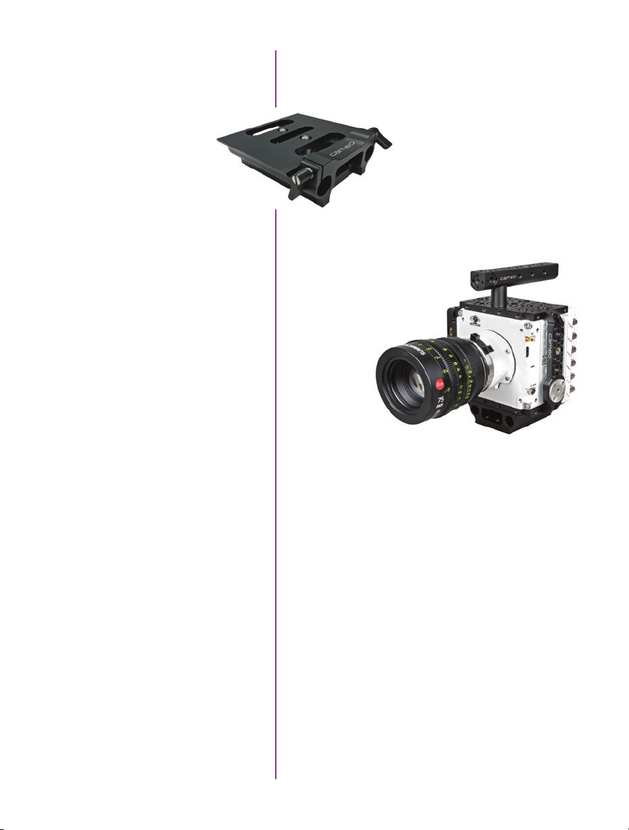
VEO Riser
Riser part # VRI-AB-CAM-VEO-RISER
The Riser is an important accessory that brings the VEO’s
optical axis to the correct height to work with standard
bridgeplates and common 35mm
film accessories. The riser
includes 15mm Rod support for
lightweight accessories like lens
supports and smaller matteboxes.
Requires cheese plate (included)
Cine Essential Kit for VEO
VEObob
Battery Solutions
Kit part # VRI-AB-CAM-VEO-CINE-KIT
The VEO essential kit includes a
top handle, riser, rosette bar
and 2 cheese plates.
The VEObob is part of Abel Cine’s CAMEO accessory line.
It has an XLR4 power input and routes power to any VEO
S-model camera. It provides additional connectivity such
as a Remote port and several 12V accessory outputs
including those that are found on a Phantom Flex4K.
With the addition of a battery mount and an on-camera
monitor or viewfinder, a VEO S-model camera becomes a
fully portable high speed camera system.
A VEO running with its maximum configuration will
consume approximately 70 watts of power.
58
Phantom VEO Manual

24V & 12V Power Input
The camera’s main power input is 24V (16-28V range).
An XLR3 battery cable exists for connecting an off-board
24V battery: Part# VRI-CBL-VEO-BATT-2
VEO-S models include a capture port which offers an
alternative 12V power input. When working with batteries
in the 12-14.4V range, ensure the battery can supply at
least 8 Amps when fully charged.
12V XLR4 Power Input Cable
12V Battery Mounts
There are a few different 12V battery mount solutions
to choose from, each of which connect to the camera’s
capture connector.
Part # VRI-CBL-VEO-S-12VBATT-0R2
This short 10-inch XLR4 is meant for connecting 12V
battery mounts (with an XLR lead), or connect a 4-pin XLR
extension cable for using other 12V power sources.
Alternatively, choose a battery mount customized to work
directly with the VEO.
Part # VRI-VEO-BATT-MNT-AB (Gold mount)
Part # VRI-VEO-BATT-MNT-VLOCK (V-Lock mount)
These mounts work with one of the Cameo cheese plates,
which are included with the mount, and the cable connects
directly to the capture port of the VEO. The recommended
position is on the side of the camera, as shown.
Phantom VEO 640S
Pictured with Cine Essential Kit
and on-board 12V Anton Bauer Gold mount.
Lens, Matte Box and Rods are not included.
59
Chapter 9: Accessories
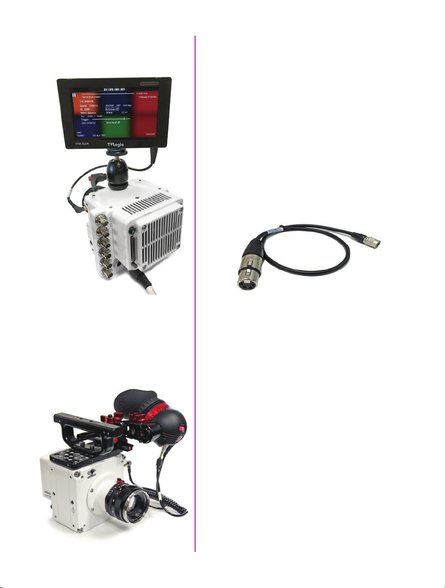
Viewfinder and Monitor
Options
Phantom VEO cameras come standard with an SDI Din,
HDMI and a 4-pin Hirose 12V VF Power output, which
supports small, low power monitors and viewfinders. The
VF output is specified for devices up to 0.9 amp (10W
when the camera is running from a 12V power source).
Larger, higher power devices must be powered from a
separate source.
Vision Research offers a few different VF power cables for
on-camera monitors including:
Hirose to 2-pin Lemo. This is for monitors and viewfinders
with a 2-pin Lemo input.
Hirose to XLR4 15 inch cable. This is for monitors with a
4-pin XLR input for power.
VEO cameras ship standard with a 12 inch SDI Din port
which is perfect for on-camera SDI monitors and viewfinders, like the one pictured at left. The SDI Din cable is
included in the camera’s ship kit.
Recommended Viewfinder
60
Phantom VEO Manual
Zacuto’s Gratical Eye Viewfinder is a great eyepiece
solution for the Phantom VEO. It features a high quality
OLED display, intuitive menu system and is small and
lightweight.
Vision Research offers a kit that includes a viewfinder
bracket and the necessary cables to connect the
Gratical Eye to Phantom VEO cameras.
Part # VRI-ZACUTO-VF-EYE-KIT
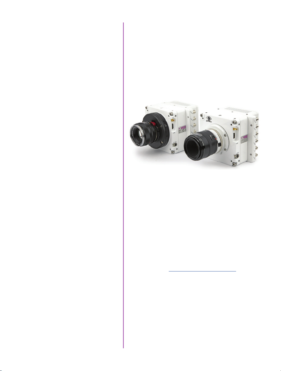
Lens Mounts
One of the main differences between the original VEO
and VEO4K models are the lens mounts that they use.
VEO 340, 640, 410 and 710 models use the same exact
mounts and OLPF as Miro R/LC/Lab cameras.
VEO4K PL, 590 and 990 models use the same mounts
and OLPF as the Flex4K, except for the C-mount which
is specific to the VEO4K. The Canon mount requires the
addition of a pin adapter (if mount is purchased with the
VEO4K part number the adapter is included).
VEO4K 990S with Nikon mount (left)
and VEO640S with Canon mount (right)
Mount Options and Description
Nikon mounts are compatible with both manual F-mount
and newer G-style lenses. A mechanical lever on the front
of the mount allows for manual adjustment of the aperture
on G-style lenses.
Canon mounts work with electronic Canon EOS lenses and
allows for control of aperture (on-camera and in software
or remote control) and focus (in software or remote control). While most Canon lenses are supported, it is a good
idea to check that your lens has been verified on the Vision
Research website www.phantomhighspeed.com. Verified
lenses can be found in the FAQs in the support section of
the website.
61
Chapter 9: Accessories

PL mounts are compatible with a wide array of manual
cinema PL lenses.
A C-mount is often required for specialized optics such as
microscope mounts for scientific imaging or small rugged
lenses for crash test applications. To install the C-mount
on a VEO4K camera, the mount ring connected to the
camera body must first be removed. Other mounts are
fastened directly onto the attached mount ring.
Optical Low Pass Filter (OLPF)
Installing a New Lens Mount
The Optical Low Pass Filter (OLPF) for color VEO 340 and
640 camera models is designed for a 10-micron pixel
and exists to reduce aliasing caused by the Bayer pattern
of the sensor. It is recommended for cinema applications.
The OLPF is mounted to a circular disc that is easily
installed under the lens mount along with the lens shims.
Part # VRI-VEO-X40-OLPF-BG
The OLPF for the VEO4K is included in VEO4K-PL models,
and available as an accessory for color 990 and 590
models. This OLPF attaches to the camera body in front
of the sensor with 2 screws. Back focus must be adjusted
after installation. Part # VRI-F4K-OLPF
Installing a new lens mount is simple. Remove the four
screws that are attaching the current lens mount (either
M2.5 or M3 depending on model). Ensure all shims that
are behind the mount are transferred to the new mount.
In the case of the Canon mount, ensure the camera is
powered down and carefully align the pins to the plug
found behind the mount. The VEO4K requires the added
pin adapter for connection. Once lined up, use the same
screws to fasten the new mount in place.
62
Phantom VEO Manual
Any time the lens mount is removed it’s
important to verify the back focus.
A set of extra lens mount shims is included
with every VEO lens mount in order to adjust
the camera’s back focus when necessary.
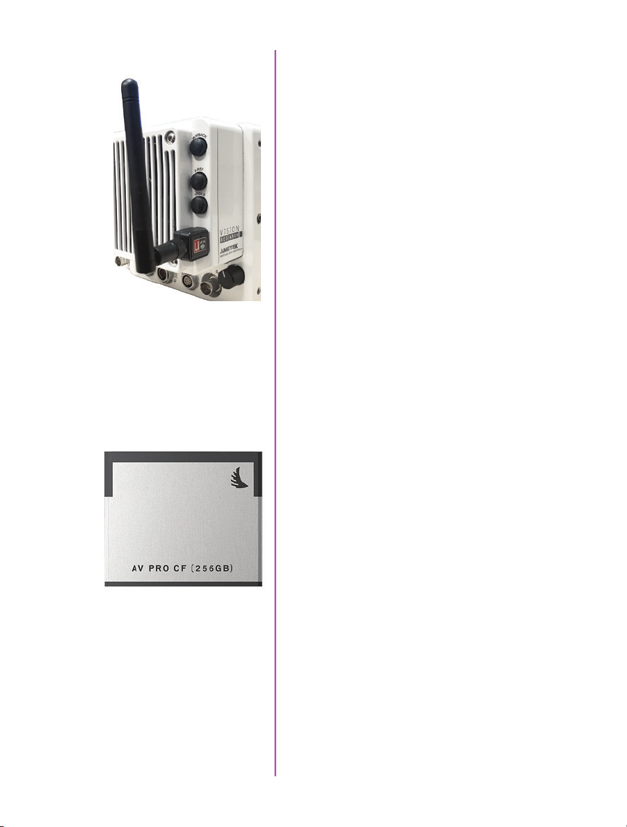
WiFi Dongle for USB Port
VEO S-model cameras must be running a minimum
firmware version 106 for the wireless functionality to work
with a USB WiFi adapter attached to the camera’s USB
port. The USB adapter must support 802.11g protocol and
it must have an RT5370 chipset for compatibility. Contact
your Vision Research representative for recommendations,
or purchase with part # VRI-USB-WIFI
To operate, the camera must be booted with the USB
adapter installed.
Once connected, the WiFi network will be visible as
“Phantom VEO…” followed by the camera model and
serial number.
The password for this is: CameraConnect
The camera can now be controlled wirelessly on a laptop
computer or using the excellent (3rd party) iPhantom IOS
app.
CFast Cards and Reader
Part #s
VRI-CFAST-128 (also available in 256 and 512 GB).
Formatted CFast 2.0 cards VRI-CFAST-READER-USB3:
A simple USB3 reader for CFast 2.0 cards.
Phantom VEO S-model cameras include compatibility with
CFast 2.0 cards. At the time of writing, Vision Research
has verified cards manufactured by Angelbird and Lexar.
VEO cameras require the card to be formatted for the
NTFS file system. More information about formatting
the cards and working with CFast cards can be found in
Chapter 5 of this manual.
63
Chapter 9: Accessories
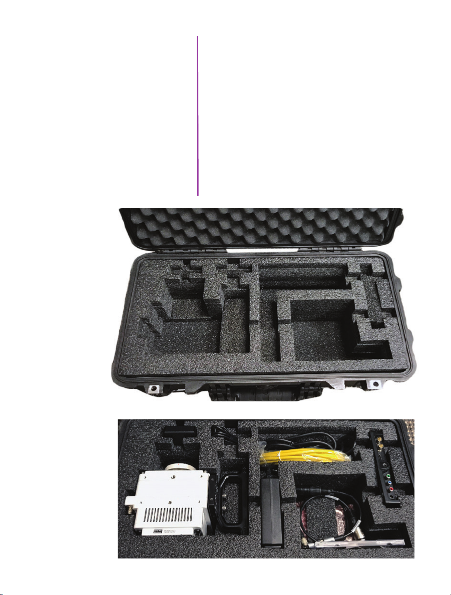
Transport Case
The popular Pelican 1510 case is the perfect size for a
Phantom VEO camera and a set of accessories. Vision
Research offers this case with custom foam that includes
space for the camera body, with or without handle and
cheese plate, plus the cable kit, small monitor, and a few
extras such as lens mounts or battery mounts. It is a very
convenient size with wheels and a handle.
Case dimensions: 22.0 x 13.8 x 9.0"
(55.9 x 35.1 x 22.9 cm)
Part numbers:
VRI-CASE-VEO (black)
VRI-CASE-VEO-TAN (desert tan color)
64
Phantom VEO Manual
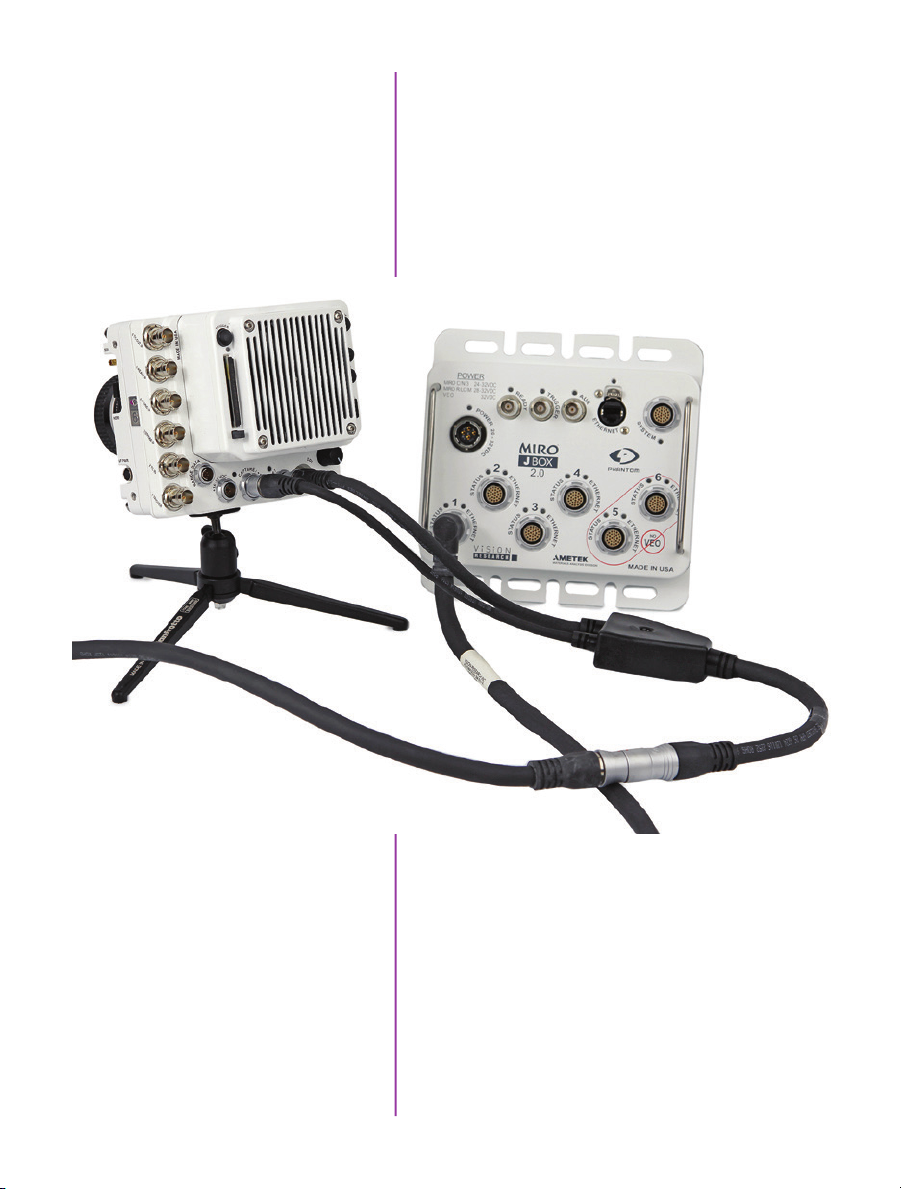
Junction Box
The updated Phantom Miro JBox 2.0 (JB2) can manage
up to 4 VEO-S camera models at once. The JB2 receives
one power input, and in turn powers and synchronizes
each connected camera with a combined system +
adapter cable as pictured. A single Ethernet cable from
the JB2 can connect to PCC for control and download.
The JB2 is compatible with Miro C, N, R, LC and all VEO
S-model cameras (not L).
65
Chapter 9: Accessories
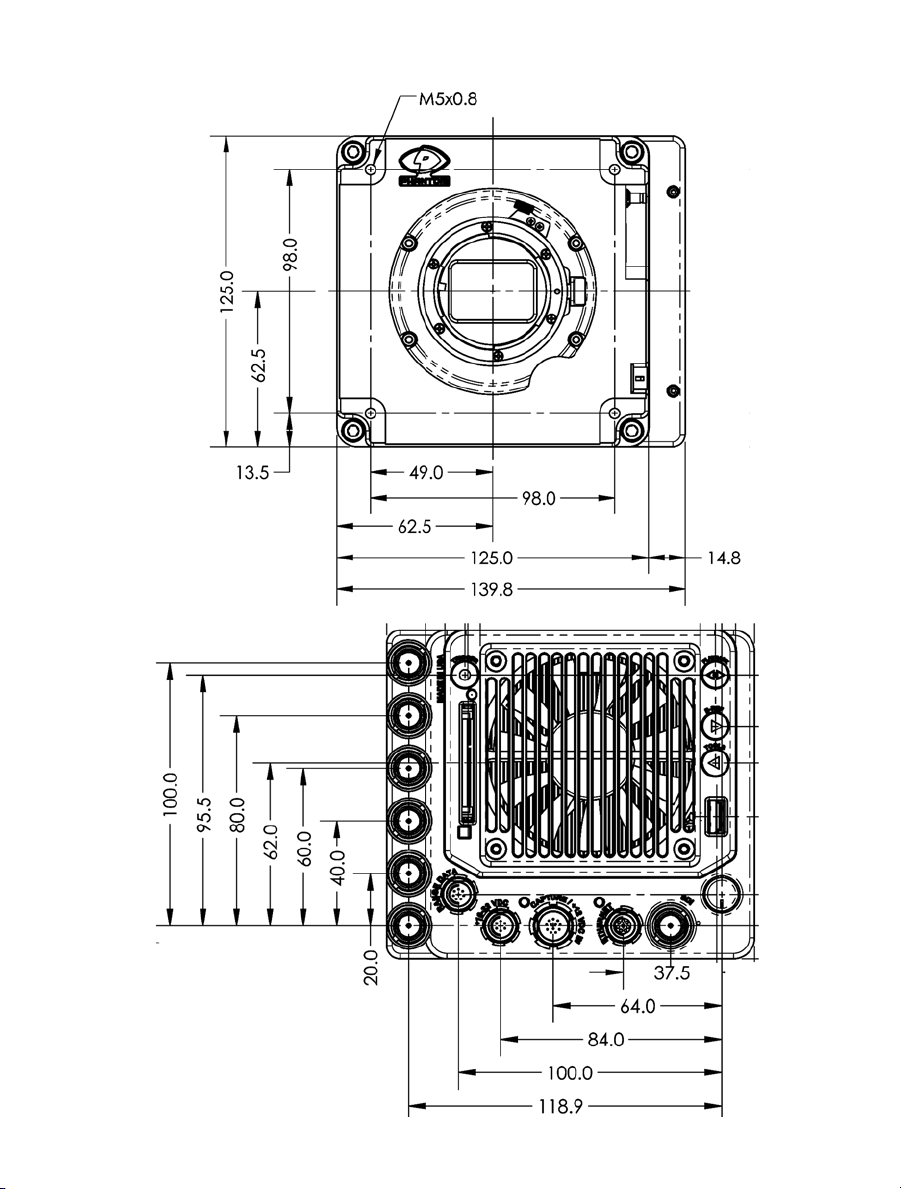
VEO S-model
Front/Back
mechanical drawings
66
Phantom VEO Manual
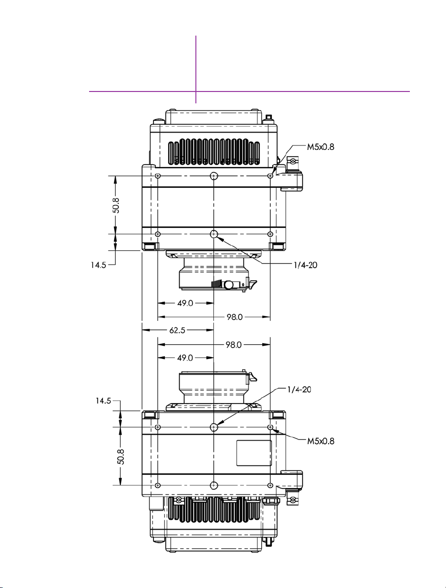
10
Support
VEO S-model
Top/Bottom
67
Chapter 10: FAQs & Support

VEO S-model
Left/ Right
68
Phantom VEO Manual
Front face with lens mount and optical plane info
does not depict VEO4K models
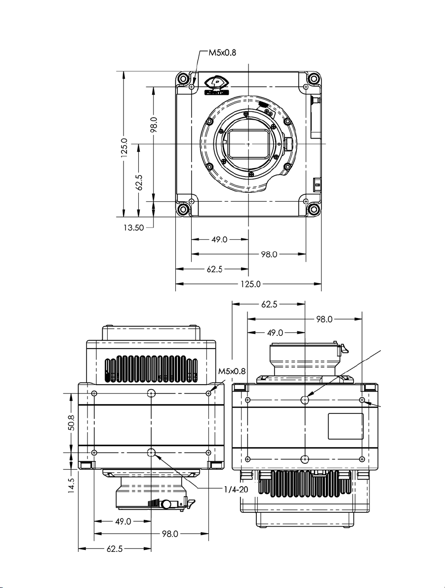
VEO L-model
Front/ Top/Bottom
69
Chapter 10: FAQs & Support

VEO L-model
Side/ Back
These drawings represent VEO x40 and x10 models. VEO4Ks are very similar
but have a different front section with lens mount. Refer to the VEO4K product
pages at www.phantomhighspeed.com for complete external drawings.
70
Phantom VEO Manual

Use these schematics to build custom cables at your own risk. Mis-wired cables
can cause serious damage to the camera, which is not covered under warranty.
Vision Research recommends only using cables supplied by Vision Research.
These pin-out diagrams refer to the connector on the camera body. Part numbers
indicated are for the cable’s connector.
6-Pin Power
+16-28VDC (Male)
4-pin 12V Viewfinder
Power (Female)
Main power port. VEO S and L models
6-pin Fischer part # SS 103 Z 056 1300
PIN NOMENCLATURE / FUNCTION
1 PGND / Power Ground
2 VDC +16-28 VDC (Direct Current)
3 RxD1 / RS-232 Receive Data 1
4 TxD1 / RS-232 Transmit Data 1
5 UNUSED
6 GND / Ground
12V Viewfinder power. VEO S and L models
4-pin Hirose part # HR10A-7P-4P
PIN NOMENCLATURE / FUNCTION
1 GND Chassis Ground
2 RTALLY Red Tally
3 GTALLY Green Tally
4 +12 VDC / up to 1.5 Amps
connector pin outs
71
Chapter 10: FAQs & Support

8-pin Ethernet (Female)
Ethernet port. VEO S models only
8-pin Fischer part # S-103-A-058-130
PIN WIRE NOMENCLATURE / FUNCTION
1 Blue/White MDI2P Media Dependent 2 Positive
2 Blue MDI2N Media Dependent 2 Negative
3 Brown/White MDI3P Media Dependent 3 Positive
4 Brown MDI3N Media Dependent 3 Negative
5 Green/White ETHRXP Ethernet Receive Positive
6 Green ETHRXN Ethernet Receive Negative
7 Orange/White ETHTXP Ethernet Transmit Positive
8 Orange ETHTXN Ethernet Transmit Negative
8-pin Range Data (Male)
Range Data port. VEO S models only
8-pin Fischer part# S103Z05813
PIN NOMENCLATURE / FUNCTION
1 GND / Power Ground
2 ROUT+ / Remote/Range Data Out (Positive), (RS-422);
+5V maximum. Depending on data transmission rates,
RS-422*
3 ROUT- / Remote/Range Data Out (Negative), (RS-422);
+5V maximum. Depending on data transmission rates,
RS-422
4 RIN+ / Remote/Range Data In (Positive), (RS-422);
+5V maximum. Depending on data transmission rates,
RS-422
5 RIN- / Remote/Range Data In (Negative), (RS-422);
+5V maximum. Depending on data transmission rates,
RS-422
6 +3V3R
7 +24VR
8 GND / Power Ground
* RS-422 up to 4,000 feet (1,275 meters).
72
Phantom VEO Manual

12-pin Capture (Male)
Capture port for optional mini-bob and 12V power input
VEO S-models only
12-pin Fischer part # S-1031-Z012-130
PIN NOMENCLATURE / FUNCTION
1 IOGND Signal ground
2 IOGND Signal ground
3 IOGND Signal ground
4 TRIGGER Isolated Input. Active low. Can be activated
by a switch to ground. Pulse must be at least 3 microseconds long.
5 P/IO 5 (Programmable) default signal is READY
6 P/IO 6 (Programmable) default signal is STROBE
7 TCIN Timecode Input can accept IRIG-B and SMPTE
standards
8 GND
9 TCIN Timecode Input can accept IRIG-B and SMPTE
standards
10 POWER / Nominal power supply voltage is +24VDC
(acceptable range is 12-36VDC)
11 POWER / (see Pin 10)
12 P/IO 6 (Programmable) default signal is TIMECODE OUT
73
Chapter 10: FAQs & Support

How is the light
sensitivity determined?
We test our cameras’ light sensitivity to an industry
standard: ISO 12232. We use the SAT method which
we think is the best method for determining a sensor’s
sensitivity. The SAT method does not use gain to boost
sensitivity. When using gain to increase sensitivity, you
also boost the noise level. Note that a gain adjustment,
and other image processing tools to boost sensitivity are
available on all Phantom cameras.
How does the Exposure
Index work?
What is a Current Session
Reference (CSR) and
phantom veo faqs
When should I use it?
Exposure Index is an image processing adjustment to
change the “effective ISO” for use when determining
exposure and lighting. It works by applying a pre-defined
tone curve to the image. This boosts the signal in a nonlinear way in order to get the most out of the sensor’s
inherent dynamic range.
The exposure index (EI) range always starts at the
camera’s base ISO level and goes up from there. Just like
any digital camera, the higher the value, the more noise however overall image degradation is noticeably less than
when compared to a linear gain adjustment.
The highest pre-set EI setting has been selected to ensure
image quality looks good throughout the range. Additional
image processing can be added beyond that pre-set. This
produces a “Combined EI” value which is shown on the
camera’s on-screen-display (OSD) and in PCC software.
The combined EI is what should be used for lighting and
exposure calculations.
Phantom cameras employ CMOS sensors, which are
made up of thousands of pixels whose sensitivity can
drift due to changes in resolution, exposure, time and
temperature. A Current Session Reference calibrates
all the pixels that will be used for a given set of camera
parameters. It is good practice to perform a CSR when the
camera boots up and after any settings changes to ensure
the best possible images.
74
Phantom VEO Manual
Phantom VEO cameras include a built in mechanical
shutter that automatically closes during the CSR, which
only takes a second. Auto-BREF can be set in the
software, or via the on-camera menu, so that whenever
the camera enters capture mode it will close the shutter
and do the CSR.

What is the difference between
Global and Rolling Shutter modes
with the VEO4K?
VEO4K models can operate with a global shutter (GS) or
rolling shutter (RS). The sensor mode can be switched
using PCC software or the On-Camera control menu. GS
mode may be necessary when the images are being used
for measurements, when synchronizing to light sources
and when known rolling shutter artifacts are anticipated.
There are differences in terms of overall image quality that
are important to understand:
In Rolling Shutter mode the VEO4K produces images
with 12.5 stops of dynamic range and a base ISO of 320
(color cameras). The low noise means the image can be
pushed to about 1250 using the Exposure Index function,
with good results.
In Global Shutter mode the same camera the dynamic
range drops to about 9 stops, and the base ISO raises to
640 (color). There is a higher amount of noise, so Vision
Research only recommends pushing the image to about
1250 when possible. In GS mode there is a greater need
to perform a Black Reference (aka CSR) before capturing
the shot.
Also keep in mind that the VEO4K only supports “PIV
mode” when set to GS mode. When enabled this keeps
the exposure at the maximum value and shortens the
straddle time between frames for PIV applications.
What remote control
options are there for VEO?
The Phantom RCU has not been updated to work with
VEO, and is therefore not recommended. However, if one
was to have an RCU with appropriate cables (same as
Miro RCU connection kit), it would still control the basic
capture, trigger and save functionality. The addition of a
VEObob (CAMEO accessory) includes a ‘remote’ port for
compatibility to a Bluetooth dongle. The VEObob also
opens up compatibility with the Abel Cine Phantom PCU.
Starting with firmware version 106, VEO S-model cameras
support WiFi control through a USB WiFi adapter. The USB
adapter must have an RT5370 chipset for compatibility.
Contact Vision Research for recommendations or purchase
with part# VRI-USB-WIFI. Please note, the camera must
be booted up with the USB adapter installed, And the
password is “CameraConnect”. This opens up connectivity
to the 3rd party iPhantom app for IOS devices.
75
Chapter 10: FAQs & Support

Another solution for remote (wired or wireless) control is
the 3rd party “Semote” controller. This allows for wireless
connectivity over the longest range when compared to the
other identified solutions, and includes compatibility with
all Ethernet-based modern Phantom cameras.
What video modes are supported?
Does the VEO support
NTSC/PAL video?
How long does it take
to save from the camera vs
from the CFast card?
The SDI and HDMI outputs found on all Phantom VEO
cameras are 3G and support the common 720p and
1080p 3G signals. The camera supports:
4:2:2 1.5G 1080p/psf/i at 23.9, 24, 25, 29.9 Hz;
720p at 50, 59.9 Hz
4:2:2 3G 1080p 50 and 59.9 Hz
VEO cameras do not include NTSC or PAL outputs.
When connected via Ethernet, it is faster to save from
RAM directly than it is to save Cine files stored on a CFast
card. The time it takes to download Cine files over Ethernet
(Gb or 10Gb) is highly dependent on the computer system
and the hard drive being used. For example, a solid state
drive will always achieve higher rates than traditional hard
drives. From RAM, on an optimized system it is possible to
achieve 70-80 MB/ sec over Gb Ethernet, and 400-500
MB/sec using 10Gb Ethernet.
The save rate from RAM to CFast 2.0 is approximately
90 MB/second. An entire 72GB RAM cine file will take
approximately 12 minutes to complete the save. It is
always recommended to review the shot and set in and
out points prior to beginning the save to optimize time and
card space.
76
Phantom VEO Manual
It is true that CFast is capable of faster data throughput.
The main reason the VEO bandwidth is limited is due to
the in-camera processing required to convert raw data to
a wrapped Cine file. It is worth noting that the save time
from the CFast 2.0 card using a reader (whether USB3
or Thunderbolt) is much faster than downloading over
Ethernet.
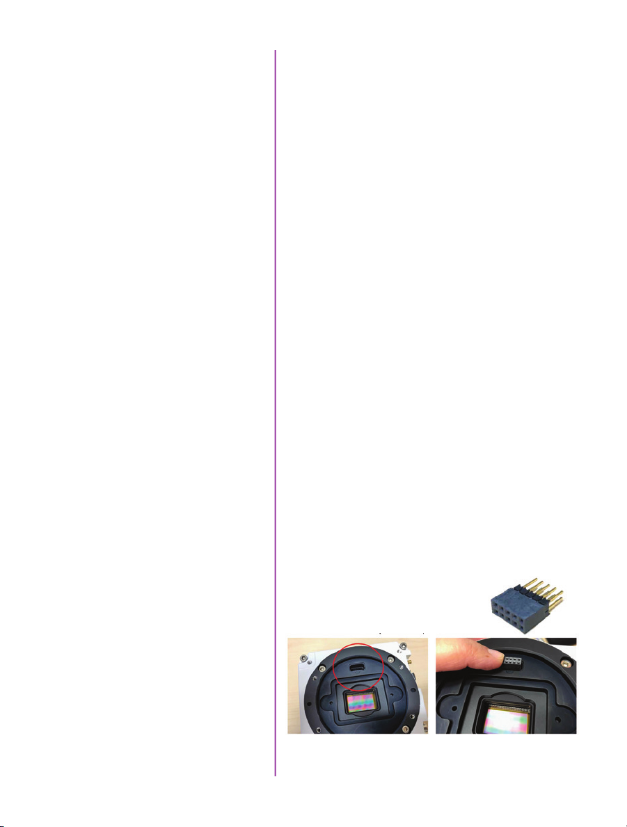
There are fixed black
spots on the image,
particularly at small
apertures.
This is most likely caused by dust particles stuck on
the sensor or OLPF (optical low pass filter) surface. The
best way to check is to remove the lens and look at the
glass surface with a bright light source. Vision research
recommends not to use canned air to clean the sensor
surface. It is safer to use a manual bulb-style air blower
and/or sensor cleaning brush for removing loose dust
particles.
Additional tips for cleaning sensors can be found in the
maintenance section of this manual.
The live images look
scrambled and the frame
rate can’t be set
Restoring the factory
defaults
The EOS mount is not
working on a VEO4K
If the image is non-responsive and scrambled, the camera
may be set to an external sync without a sync source
connected. Check the Sync setting (advanced settings in
PCC, or via the on-camera control menu) to ensure that
‘Internal’ is selected.
If the camera is stuck in an unusual state it may be useful
to restore the camera’s factory defaults. This returns the
capture parameters, image processing, video modes, and
image calibration back to the original settings.
Factory Defaults can be set in the Nucleus program
within PCC, or via the ‘Settings’ menu of the OCC. Select
‘Factory defaults’ / ‘OK’. It will take approximately 20
seconds for the camera to return to an operational state.
VEO4K cameras use the same Canon mount as the
Phantom Flex4K. This mount has pins on the back,
which must be extended to meet the port on the front of
the camera. When purchasing the mount using the VEO4K
part number, a pin adapter is included. When using the
same mount as the Flex4K, the adapter
can be purchased with part # VRIADAPT-FLEX4KEOS-VEO4KEOS.
basic troubleshooting
Note that VEO x10 and x40 models use a different style
Canon mount (the same one as Miro cameras).
77
Chapter 10: FAQs & Support

Sensor & OLPF Cleaning
Technical Tips
• Sensor cleaning should only be attempted by
experienced imaging professionals.
• Use a small, but powerful flashlight to look at the
sensor and filter, it’s easier to spot the dust.
• The OLPF assembly is removable and located in front
of the sensor. Once the lens mount is uninstalled the
OLPF can be easily removed for cleaning.
• Sensor cleaning must be done in a clean and
controlled environment
• Always have a forced-air bulb style blower and a
clean sensor cloth handy for more serious dirt.
• Sensor cleaning solution (like Eclipse) should only be
used if absolutely necessary, and applied with a soft
wipe intended for sensor cleaning.
• Cotton swabs aren’t a good idea, unless they are
wrapped in a sensor wipe material. They leave
behind more than they remove.
• Never use your finger to get a speck of dust off, it’s
going to make things much worse.
• Never blow on the sensor or OLPF.
maintenance
• Never put sharp objects near the surface of the OLPF
or sensor.
• Always keep the Phantom body cap on the camera
when there is no lens attached.
78
Phantom VEO Manual
Back Focus Adjustment
Due to differences in various lenses and other mechanical
tolerances it may be necessary to adjust the lens mount
on the camera to obtain proper focus. In most cases,
changing a lens or replacing a mount will not require
adjusting the back focus, though it should be verified.
When the focus distance marks on a lens do not match
the measured distance between the sensor & subject, it
indicates the need to adjust the back focus.
By adjusting the back focus, you are changing the
distance of between the flange and the sensor plane.
Shims are included to assist in both slight and coarse
backfocus adjustments.

Global Headquarters
Vision Research, Inc. - Wayne, New Jersey
100 Dey Road
Wayne, New Jersey 07470 USA
T: +1.973.696.4500
For answers to most questions, please visit us at:
www.phantomhighspeed.com and search the camera
product pages, tutorials, support knowledgebase, and
FAQs.
Submitting a
Support Ticket
Live Customer and
Technical Support
For technical product support, operation, application info
or to request an RMA please submit a ticket by filling out
a form at www.phantom-service.force.com or by emailing
us at phantom-support@ametek.com.
Serving the Americas:
M-F 8:00 AM to 5:00 PM EST (GMT-4:00)
T: +1.973.696.4500
Customer Support, extension 4002
Technical Support, extension 4003
Serving Europe, the Middle East and Africa:
M-F 9:00 AM to 6:00 PM GMT +3:00
Vision Research, Inc. - Bucharest, Romania
T: +40 21 210 8587
Serving Asia Pacific
M-F 8:00 AM to 5:00 PM GMT +8:00
Vision Research, Inc. - Shanghai, China
contacting support
T: 86-21- 58685111, ext:141
79
Chapter 10: FAQs & Support
또는
지역에서
regulatory
CE - 2016
Phantom VEO products are in compliance with the requirements
of the Low Voltage Directive (LVD) 2014/35/ EU, the Electromagnetic Compatibility (EMC) Directive 2014/30/EU and the Federal
Communications Commission (FCC) CFR 47, Part 15 at the time
of product manufacture and carries the CE-marking.
KC - 2016
Vision Research
Approval Issue: November 2016
Country of Origin: USA
MSIP-REM-VRi-Phantom-VEO-L
VEO-710L, VEO-640L, VEO410L and VEO340L
MSIP-REM-VRi-Phantom-VEO-S
VEO-710S, VEO-640S, VEO410S and VEO340S
For Class B devices:
이기기는가정용(B급)전자파적합기기로서주로
가정에서사
사용할수있습니다.
Translation: Class B device (Broadcasting Communication Device
for Home Use): This device obtained EMC
registration mainly for home use (Class B) and may
be used in all areas.
용하는것을목적으로하며,모든지역에서
80
Phantom VEO Manual
KC Mark Location
KC - 2017
Vision Research
Approval Issue: December 2017
Country of Origin: USA
R-REM-VRi-VEO4K-L: VEO4K-990L, VEO4K-590L
R-REM-VRi-VEO4K-S: 4K-990S, 4K-590S, 4K-PL
For Class A devices:
이기기는업무용(A급)전자파적합기기로서판매자
사용자는이점을주의하시기바라며,가정외의
사용하는것을목적으로합니다.
Translation: Class A device (Broadcasting Communication
Device for Office Use): This device obtained EMC registration
for office use (Class A), and may be used in places other than
home. Sellers and/or users need to take note of this.

Change Log for VEO Manual
Rev B
- Added VEO4K (590, 990, PL) product information
- Added 10Gb Ethernet networking guide
- Added new on-camera menu parameters relating to
VEO4K models
- Added info about the USB WiFi dongle and relevant
settings

Vision Research - Corporate Headquarters
100 Dey Road
Wayne, New Jersey 07470
USA
Ph: +1.973.696.4500
Fax: +1.973.696.0560
w w w . p h a n t o m h i g h s p e e d . c o m
Phantom VEO Manual
PN: ZDOC-64109-MA-0001 Rev B
 Loading...