

VisionQuest PVQ-32VGB Owner's Manual
Please READ this manual carefully before
operating your TV, and retain it for future
reference.
PLASMA TV
OWNER S MANUAL'
MODEL :
S PVQ-32VGB
2 PLASMA TV
THIS SYMBOL INDICATES THAT HIGH VOLTAGE IS PRESENT
INSIDE. IT IS DANGEROUS TO MAKE ANY KIND OF CONTACT
WITH ANY INSIDE PART OF THIS PRODUCT.
WARNING : To reduce the risk of electric shock do not remove cover or back.
No user-serviceable parts inside refer service to qualified service personnel.
This equipment has been tested and found to comply with the limits for a Class B digital device, pursuant to Part 15 of the
FCC Rule. These limits are designed to provide reasonable protection against harmful interference in a residential
installation. This equipment generates, use and can radiate radio frequency energy and, if not installed and used in
accordance with the instructions, may cause harmful interference to radio communications. However there is no
guarantee that interference will not occur in particular installation. If this equipment does cause harmful interference
to radio or television reception, which can be determined by turning the equipment off and on, the user is encourage to
try to correct the interference by one or more of the following measures:
*Reorient or relocate the receiving antenna.
*Increase the separation between the equipment and receiver.
*Connect the equipment into an outlet on a circuit different from that to which the receiver is connected.
*Consult the dealer or an experienced radio/TV technician for help.
This device compiles with Part 15 of the FCC Rules. Operation is subject to the following two conditions:
(1) This device may be not cause harmful interference.
(2) this device must accept any interference received, including interference that may cause undesired
operation.
FCC CAUTION:
To assure continued compliance and possible undesirable interference, the provided ferrite cores must be
used when connecting this plasma display to video equipment; and maintain at least 40cm spacing to other
peripheral device.
CANADIAN NOTICE:
This Class B digital apparatus compiles with Canadian ICES-003.
RISK ELECTRIC SHOCK
DO NOT OPEN
WARNING
Operator Safety has been taken into consideration at the design and manufacture phase, but inappropriate operation may
cause electric shock or fire. To prevent the product from being damaged, the following rules should be observed for the
installation, use and maintenanceof th product. Read the following safety instruction before starting the operation.
The User Manual uses the following symbols to ensure a safe operation and prevent any damage to operators
or properties:
THIS SYMBOL INDICATES THAT THERE ARE IMPORTANT
OPERATING AND MAINTENANCE INSTRUCTIONS IN THE
LITERATURE ACCOMPANYING THE APPLIANCE.
FCC STATEMENT
Warning

Owner s Manual 3
IMPORTANT SAFETY INSTRUCTIONS
Read all of the instructions before using this appliance. When using this
appliance, always exercise basic safety precautions, including the following:
1) Read these instructions.
2) Keep these instructions.
3) Heed all warnings.
4) Follow all instructions.
5) Do not use this apparatus near water.
6) Clean only with dry cloth.
7) Do not block any ventilation openings. Install in accordance with the manufacturer`s instructions.
8) Do not install near any heat sources such as radiators, heat registers, stoves, or other apparatus
(including amplifiers) that produce heat.
9) Do not defeat the safety purpose of the polarized or grounding-type plug. A polarized plug has two blades
with one wider than the other. A grounding type plug has two blades and a third grounding prong. The wide
blade or the third prong are provided for your safety. If the provided plug does not fit into your outlet, consult
an electrician for replacement of the obsolete outlet.
10) Protect the power cord from being walked on or pinched particularly at plugs, convenience receptacles,
and the point where they exit from the apparatus.
11) Only use attachments/accessories specified by the manufacturer.
12) Use only with the cart, stand, tripod, bracket, or table specified by the manufacturer,
or sold with the apparatus. When a cart is used, use caution when moving the cart/
apparatus combination to avoid injury from tip-over.
13) Unplug this apparatus during lightning storms or when unused for long periods of
time.
14) Refer all servicing to qualified service personnel. Servicing is required when the
apparatus has been damaged in any way, such as power-supply cord or plug is
damaged, liquid has been spilled or objects have fallen into the apparatus, the
apparatus has been exposed to rain or moisture, does not operate normally, or has been dropped.
15) WARNING-to reduce the risk of fire or electric shock, do not expose this apparatus to rain or moisture.
Apparatus shall not be exposed to dripping or splashing and no objects filled with liquids, such as vases,
shall be placed on the apparatus.
The apparatus shall not be exposed to dripping or splashing and that no objects filled
with liquids, such as vases, shall be placed on the apparatus.
The mains plug is used as the disconnect device, remain it readily operable during the
apparatus normal use.
S3126A
PORTABLE CART WARNING
(symbol provided by RETAC)
Safety Instructions

SAVE THESE INSTRUCTIONS
Thank you for purchasing the VisionQuest product. This easy-to-use manual will guide you in getting the best
use of your
product. Remember to record the model and serial number. They are on label in back of the unit.
Model number
serial number
Date of purchase
Staple your receipt to your manual. You will need it to obtain warranty service.
Safety Instructions
4 PLASMA TV

Introduction
Owner s Manual 5
Warning
Safety Instructions
Introduction
Controls
Connection Options
Universal Remote Control
Installation
Accessories
Antenna Connection
VCR Connection
External A/V Source Setup
DVD Connection
DTV Connection
Digital Audio Output
PC Connection
HDMI
Cable sample
Connecting Headphones
Power source
Operation
Switching On/Off the TV set
Choose the Menu Language
Choose the input source
Channel Menu
Automatic Scan
Add Channel Scan
Rename
Video Menu
Audio Menu
SAP Broadcasts Setup
Take the table stand off
Select the desired program
Select the desired sound
Mute
How to select picture mode
How to customize your own picture status
How to select audio mode
How to customize your own audio status
Time Menu
Date /Time setting
Time zone setting
Sleep Timer setting
Timer on setting
Timer off setting
Function Menu
Menu Language
DTV Caption Style
OSD Timeout
OSD Transparency
DNR
Adjust Menu
Screen Setup for Component or PC mode
Lock Menu
Parental Control rating and categories
Lock setup
Other Functions
Brief Info
Quick program view
Aspect Ratio Control
CC (Closed Caption Display)
Remote Control
Setting up your remote control
Remote Control Codes
Maintenance
Product Specifications
Troubleshooting
. . . . . . . . . . . . . . . . . . . . . . . . . . . . . . . . . . . . . . . .
. . . . . . . . . . . . . . . . . . . . . . . . . . . . . .
. . . .. . . . . . . . . . . . . . . . . . . . . . . . . . . . . . . . . . . .
. . .. . . . . . . . . . . . . . . . . . . . . . . . . . .
. . . . . . . . . . . . . . . . . . . . . . . .
. . . . . . . . . . . . . . . . . . . . . . . . . . . . . . . . . . . .
. . . . . . . . . . . . . . . . . . . . . . . . . . . . .
. . . . . . . . . . . . . . . . . . . . . . . . . . . . . . .
. . . . . . . . . . . . . . . . . . . . . . .
. . . . . . . . . . . . . . . . . . . . . . . . . . . . . . .
. . . .. . . . . . . . . . . . . . . . . . . . . . . . . . . .
. . . . . . . . . . . . . . . . . . . . . . . . . . . .
. . .. . . . . . . . . . . . . . . . . . . . . . . . . . . . . .
. . . . . . . . . . . . . . . . . . . . . . . . . . . . . . . . . . . . . . . . .
. . . . . . . . . . . . . . . . . . . . . . . . . . . . . . . . . .
. . . . . . . . . . . . . . . . . . . . . . .
. . . . . . . . . . . . . . . . . . . . . . . . . . . . . . . . . .
. . . . . . . . . . . . . . . . . . . . . . . . .
. . . . . . . . . . . . . . . . . . . . . .
. . . . . . . . . . . . . . . . . . . . .
. . .. . . . . . . . . . . . . . . . . . . . . .
. . . . . . . . . . . . . . . . . . . . . . . . . . . . . . . .
. . .. . . . . . . . . . . . . . . . . . . . . . . . . . .1 9
. . . . . . . . . . . . . .. . . . . . . . . . . . . . . . . . . . . . . . .
. . . . . . . . . . . . . . . . . . . . . .
. . . . . . . . . . . . . . . . . . . . . . . .
. . . . . . . . . . . . . . . . . . . . . . . . . . . . . . . . . . . . . . . . .
. . . . . . . . . . . . . . . . . . . . . .
. . . . . . . . . .
. . . . . . . . . . . . . . . . . . . . . . .
. . . . . . . . . . .
. . . . . . . . . . . . . . . . . . . . . . . . . .
2
3
6
7
8
9
9
10
11
11
12
12
13
14
15
16
16
17
18
18
18
19
20
20
20
20
21
21
22
22
23
. . . . . . . . . . . . . . . . . . . . . . . . . . . . . .
. . . . . . . . . . . . . . . . . . . . . . . . . . . . . . .
. . . . . . . . . . . . . . . . . . . . . . . . . . . . .
. . . . . . . . . . . . . . . . . . . . . . . . . . . . . . . .
. . . . . . . . . . . . . . . . . . . . . . . . . . . . . . . .
. . . . . . . . . . . . . . . . . . . . . . . . . . . . . . . .
. . . . . . . . . . . . . . . . . . . . . . . . . . . . . .
. . . . . . . . . . . . . . . . . . . . . . . . . . . . . . . . . . .
. . . . . . . . . . . . . . . . . . . . . . . . . . . . . .
.. . . . . .. . . . . . . . . . . . . . . . . . . . . . . . . . . . . . . . . . . .
. . . . . . . . . .
. . . . . . . . . . . . .
.. . . . . . . . . . . . . . . . . . . . . . . . . . . . . . . . . . . .2 9
. . .. . . . . . . . . . . . . . . . . . . . . . . . . . . . . . . . . . . .
. . . . . . . . . . . . . . . . . . . . . . . . . . . . .
. . . . . . . . . . . . . . . . . . . . . . . . . . . .
. . . . . . . . . . . . . . . . . . . . .
. . . . . . . . . . . . . . . . . . . .
. . . . . . . . . . . . . . . . . . . . . . . . . . .
. . . . . . . . . . . . . . . . . . . . . . . . . . . . . . . . . .39
. . . . . . . . . . . . . . . . . . . . . . . . .
. . . . . . . . . . . . . . . . . . . . . . . . . . . . . . .
23
24
24
25
25
25
26
27
27
27
27
28
31
31
32
32
33
35
40
41
Contents
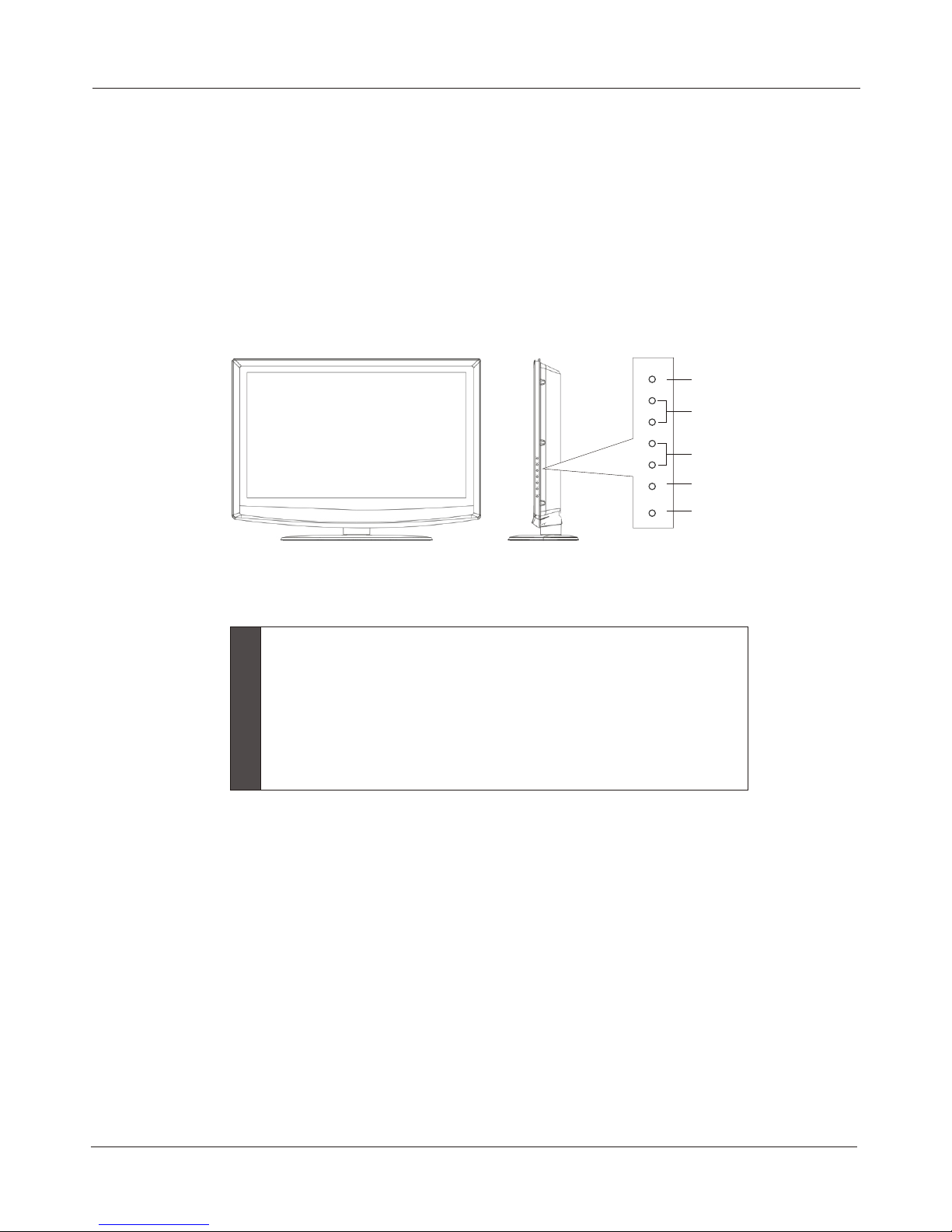
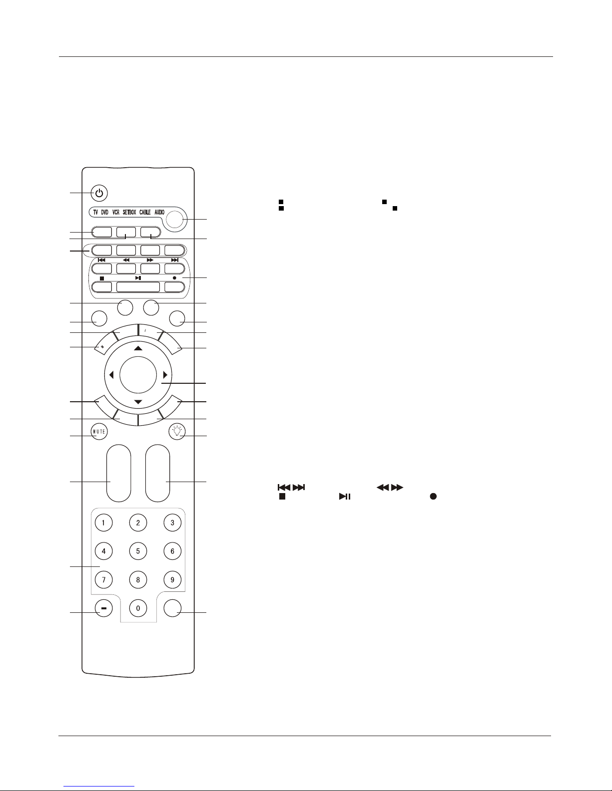
Front panel controls
This is a simplified representation of front panel.
Here shown may be somewhat different from your TV.
Introduction
Controls
INPUT
MENU
VOL+
VOL-
CH+
CH-
POWER
1
2
3
4
5
6 PLASMA TV
1
2
3
4
5
INPUT: Press to show the input source mode. In the MENU/INPUT
screen, these buttons serve as OK buttons.
CH : Press to scan through channels. To scan quickly through
channels, press and hold down either +/- . In the MENU
screen, these buttons serve as up/down buttons.
VOL : Press to adjust the volume .In the MENU screen, these
buttons serve as left/right buttons.
MENU: Menu display.
POWER: Press to turn on and off the TV.
-/+
-/+
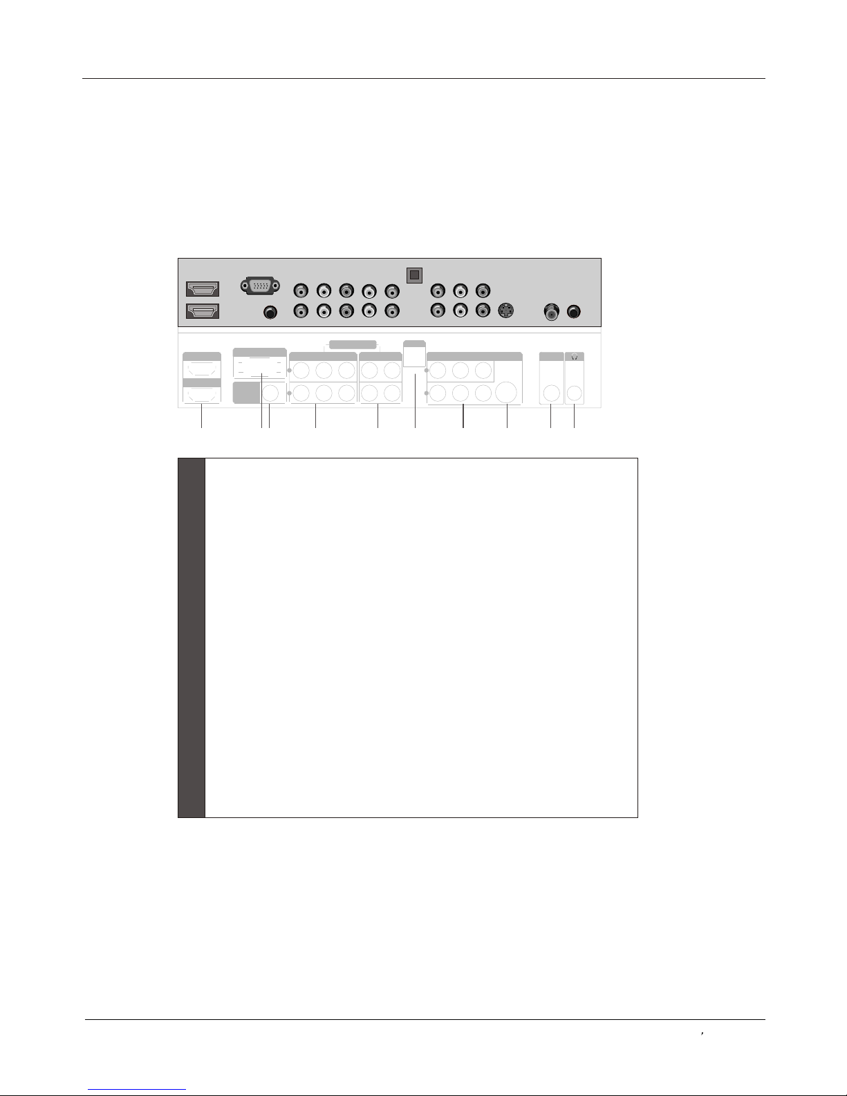
Back panel controls
Introduction
Owner s Manual 7
Connection Options
AUDIOVIDEO
HDMI/DVI 1
HDMI/DVI 2
PC IN
PC/DVI
AUDIO IN
1
2
Y
Pb Pr
COMPONENT IN
L R
OPTICAL
VEDIO IN
L R
S-VEDIO
ANT IN
1
2
1
2
3
4
5
6
7
8
9
10
HDMI
connect a signal toHDMI/DVI.
Connect the monitor output connector from a PC to the jack.
PC/DVI Audio Input
Connect the audio out from the external device, used while linking PC
audio frequency output terminals or using a DVI to HDMI connector.
DVD/DTV Input(Component )
Connect a component video device to these jacks.
COMPONENT AUDIO Input
Connect to hear stereo sound from an external device.
Digital Audio Output
Connect digital audio from various types of equipment.
Note: In standby mode, these ports will not work.
VIDEO Input
Connects the video signal from a video device.
Antenna Input
Connect cable or antenna signals to the TV, either directly or through
your cable box.
PC VIDEO Input
S-Video Input
Connect S-Video out from an S-VIDEO device to the S-VIDEO input.
Headphone jack
Headphone audio output terminal.
1 2 3 4
5
6
7
8 9 10
CH.LIST
VIDEO
S-VIDEO
COMPONENT
CC
P.MODE
S.MO DE
FREEZE
E
N
U
TIM
E
NPUT
INFO
E
X
IT
R
A
C
S
A
P
S
L
E
E
P
VOL +
CH+
Q.VIEW
OK
VOL-
CH-
The remote control cannot be operated unless the batteries are properly loaded.
When using the remote control, aim it at the remote control sensor on the TV.
Function introduction
Introduction
HDMI
SELECT
TV
PC
Universal Remote Control
8 PLASMA TV
1
2
3
4
5
6
7
8
9
10
11
12
13
14
15
16
17
18
19
20
21
22
23
24
25
26
27
1 POWER
.
2 CH.LIST
Open the channel list.
3 HDMI
Press to enter HDMI signal.
4
TV:Press to enter TV signal; S-VIDEO: Press to enter S-VIDEO signal;
VIDEO:Press to enter VIDEO signal; : Press to enter COMPONENT signal.
5 P.MODE
Selects the picture mode appropriate for the program's character.
6 CC(closed caption)
Select a closed caption.
7 TIME
Shows time.
8 MENU
Brings up the main menu to the screen.
9 EXIT
Clears all on-screen displays and returns to TV viewing from any
menu.
10 ARC(Aspect Ratio Control)
Changes the aspect ratio.
11 MUTE
Switches the sound on or off.
12 VOLUME UP/DOWN
Press to adjust the volume.
13 Numeric buttons
Press to change the channel.
14 - button
Press to select additional channels (digital )being broadcast by
the same station. For example, to select channel “54-3”, press
“54”, then press “-” and “3”.
15 TV DVD VCR SETBOX CABLE AUDIO
Press the SELECT button repeatedly to select one of the system modes
in which the remote control can be used. When the desired device is
selected, the corresponding LED lights on 5 seconds.
16 PC
Press to enter PC signal.
17
S.MODE
Selects the sound mode appropriate for the program's character.
19 FREEZE
Freezes the currently-viewed picture, but audio continues.
Press FREEZE button again to resume the normal picture.
20
INFO
When you watch the TV, press the key, the information displays
on top of the screen.
22
Displays the Sleep Timer option.
24 SAP
Selects MTS sound: Mono, Stereo, and SAP in Analog mode.
Change the audio language in DTV mode.
25
CHANNEL UP/DOWN
Q.VIEW
Switch the current channel to the last channel you have viewed.
Press to turn on and off the TV
VCR/DVD Functions
Control some video cassette recorders or DVD players.
/ Rewind / Fast / backward /Forward
Stop Play/Pause REC
18
INPUT
Show the input source mode.
21
THUMB STICK (Up/Down/Left/Right/OK)
Allows you to navigate the on-screen menus and adjust the
system settings to your preference.
23 SLEEP
LIGHT
Press the light button, white LED will be ON, release this key,
white LED will be OFF.
26
Press to scan through channels. To scan quickly through
channels, press and hold down either +/- .
27
Shortcut Button of Input
COMPONENT
ANT IN
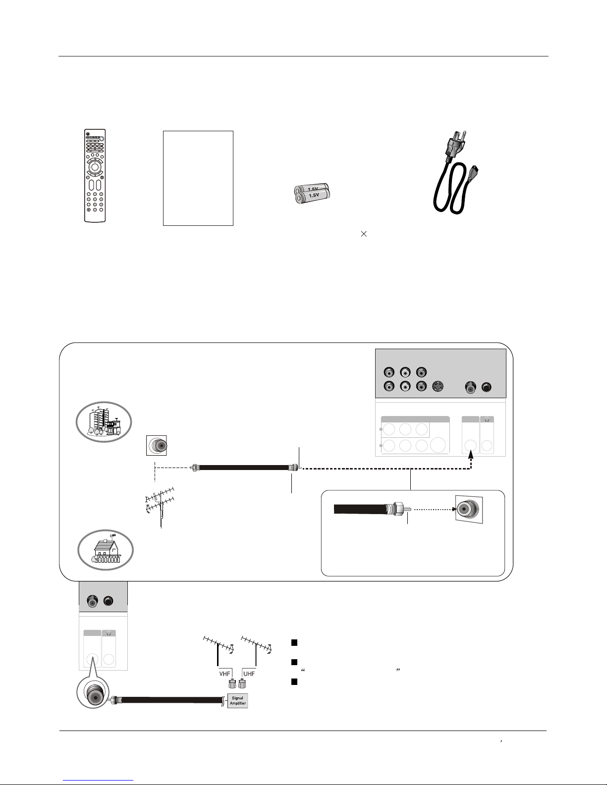
Generally speaking, to enjoy a clearer picture, we recommend that you use a CATV system or an
outdoor antenna .
.
Over-the-air TV reception quality will depend on your antenna type, antenna
location and antenna positioning
External Equipment Connections
Antenna Connection
Multi-family Dwellings/Apartments
(Connect to wall antenna socket)
Wall Antenna
Socket
Single-family Dwellings /Houses
(Connect to wall jack for outdoor antenna)
Outdoor
Antenna
VHF Antenna
UHF Antenna
Turn clockwise to tighten
RF Coaxial Wire (75 ohm)
Bronze Wire
Be careful not to bend the bronze wire
when connecting the antenna.
Bronze Wire
To improve the picture quality in a poor signal area,
please purchase a signal amplifier and install properly.
If the antenna needs to be split for two TV`s, install
a 2-Way Signal Splitter in the connections.
To install the antenna properly please contact a
professional in your area.
Installation
Accessories
Remote control
Owner`s manual
Alkaline battery(AAA) 2
Power cable
Owner s Manual 9
CH.LIST
VIDEO
S-VIDEO
COMPONENT
CC
P.MODE
S.MODE
FREEZE
E
N
U
T
IM
E
N
P
U
T
IN
F
O
E
X
I
T
R
A
C
S
A
P
S
L
E
E
P
VOL+
CH+
Q.VIEW
OK
VOL-
CH-
HDMI
SELECT
TV
PC
VEDIO IN
L R
S-VEDIO
1
2
ANT IN
Please READ this manual carefully before
operating your TV, and retain it for future
reference.
PLASMA TV
OWNER S MANUAL'
VEDIO IN
L R
S-VEDIO
1
2
ANT IN
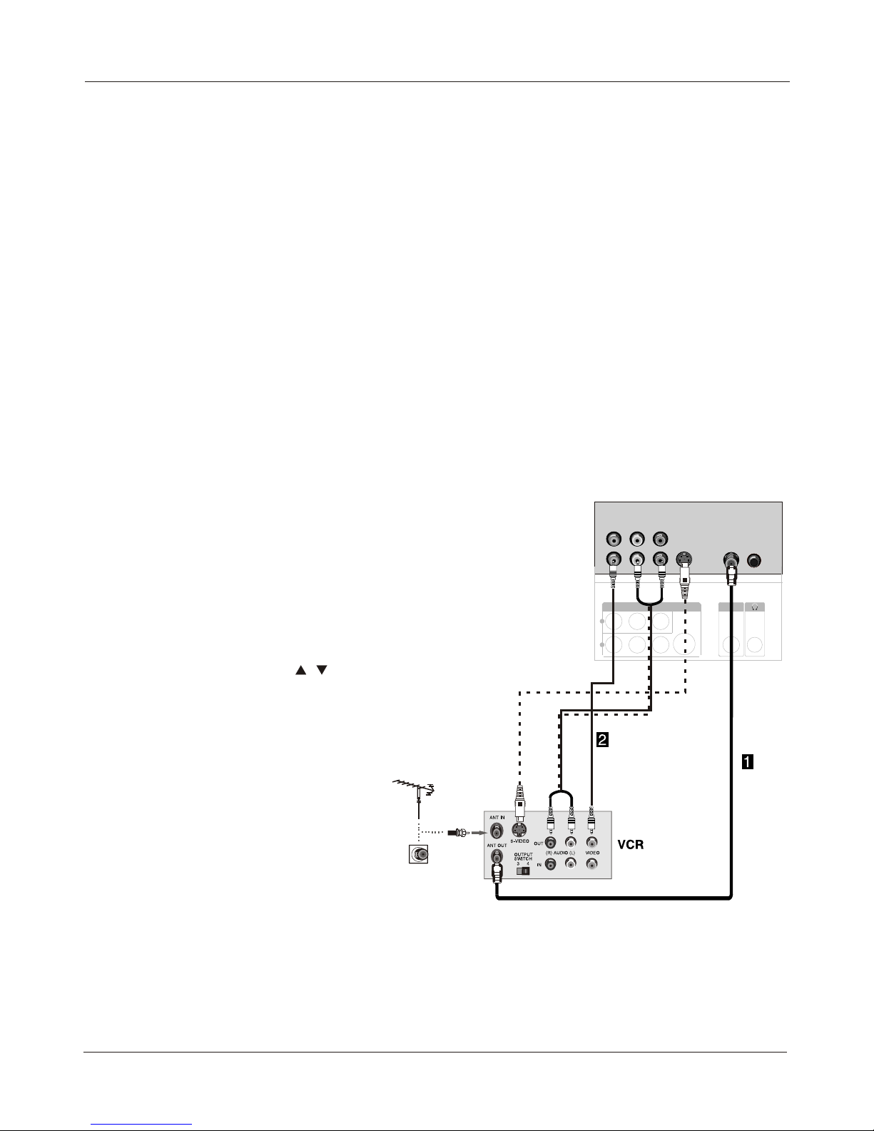
VCR connection
NOTE: All cables shown are not included with the TV.
External Equipment Connections
Choose Your Connection
Installation
10 PLASMA TV
There are several ways to connect your television,
depending on the components you want to connect and the
quality of the signal you want to achieve. The following are
examples of some different ways to connect your TV with
different input sources.
To avoid picture noise (interference), leave an adequate
distance between the VCR and TV.
Connection Option 1
Set VCR output switch to channel 3 or 4 and then tune the
TV to the same channel number.
Connection Option 2
1. Connect the audio and video cables from the VCR's
output jacks to the TV input jacks, as shown in the figure.
When connecting the TV to VCR, match the jack colors
(Video = yellow, Audio Left = white, and Audio Right = red).
If you connect an S-VIDEO output from VCR to the S-VIDEO
input, the picture quality is improved; compared to
connecting a regular VCR to the Video input.
2. Insert a video tape into the VCR and press PLAY on the
VCR. (Refer to the VCR owner`s manual.)
3. Select the input source with using the INPUT button on
the remote control, and then press / button to select the
source, press the OK button to confirm.
AUDIOVIDEO
1
2
Y
Pb Pr
COMPONENT IN
L R
OPTICAL
VEDIO IN
L R
S-VEDIO
ANT IN
1
2
VEDIO IN
L R
S-VEDIO
1
2
ANT IN
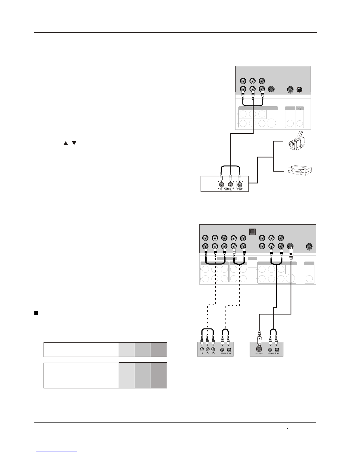
How to connect
1. Connect the DVD video outputs (COMPONENT) to the Y
Pb Pr jacks on the TV and connect the DVD audio outputs to
the Y Pb Pr Audio IN jacks on the TV, as shown in the figure.
2. If your DVD only has an S-VIDEO output jack, connect
this to the S-VIDEO input on the TV. as shown in the figure.
Note
If your DVD player does not have component video output,
use S-Video.
How to use
1. Turn on the DVD player, insert a DVD.
2. Use the INPUT button on the remote control to select Y Pb
Pr mode.
3. Press Play button on external equipment for program play.
4. Refer to the DVD player's manual for operating
instructions.
External Equipment Connections
Video Game Set
Camcorder
Component Input ports
To get better picture quality, connect a DVD player to the
component input ports as shown below.
Installation
Component ports
on the TV
Video output ports
on DVD player
Y Pb Pr
Y Pb Pr
Y B-Y R-Y
Y Cb Cr
Y P P
BR
Note
The audio input terminal of AV IN 1 is compared with S-VIDEO.
External A/V Source Setup
DVD connection
Owner s Manual 11
DVD
or
How to connect
Connect the audio and video cables from the external
equipment's output jacks to the TV input jacks, as shown
in the figure. When connecting the TV to external equipment,
match the jack colors (Video = yellow, Audio Left = white,
and Audio Right = red).
How to use
1. Select the input source with using the INPUT button on
the remote control.
2. Press the / button to select the desired source.
3. Press the OK button to confirm.
4. Operate the corresponding external equipment.
OPTICAL
VEDIO IN
L R
S-VEDIO
1
2
AUDIOVIDEO
HDMI/DVI 2
HDMI/DVI 1
PC IN
PC/DVI
AUDIO IN
1
2
Y
Pb Pr
COMPONENT IN
L R
OPTICAL
VEDIO IN
L R
S-VEDIO
1
2
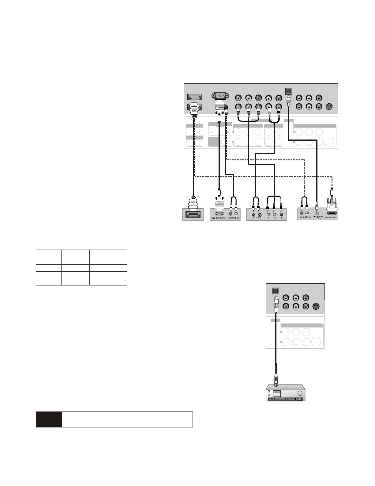
Digital Set-top Box
Digital Audio Output
Do not look into the optical output port. Looking
at the laser beam may damage your vision.
External Equipment Connections
DTV connection
Installation
Signal
480i
480p
720p
1080i
COMPONENT
HDMI/DVI
Yes
Yes
Yes
Yes
Yes
Yes
Yes
Yes
HDMI
12 PLASMA TV
This TV can receive Digital Over-the-air/Cable signals
without an external digital set-top box. However, if you
do
receive Digital signals from a digital set-top box or other
digital external device, refer to the figure as shown
below.
This TV supports HDCP (High-bandwidth Digital
How to connect
Use the TV`s COMPONENT , PC or HDMI/DVI jack for
video connections, depending on your set-top box
connector. Then, make the corresponding audio
connections.
How to use
1. Turn on the digital set-top box. (Refer to the owner`s
manual for the digital set-top box.)
2. Use INPUT on the remote control to select
COMPONENT , PC or HDMI/DVI source.
Send the TV`s audio to external audio equipment (stereo
system) via the Digital Audio Output (Optical) port.
How to connect
1. Connect one end of an optical cable to the TV Digital
Audio(Optical) Output port.
2. Connect the other end of the optical cable to the digital
audio (optical) input on the audio equipment.
See the external audio equipment instruction manual for
operation.
Note
When connecting with external audio equipments, such as
amplifers or speakers, please turn the TV speakers off.
Caution
HDMI/DVI 1
HDMI/DVI 2
PC IN
PC/DVI
AUDIO IN
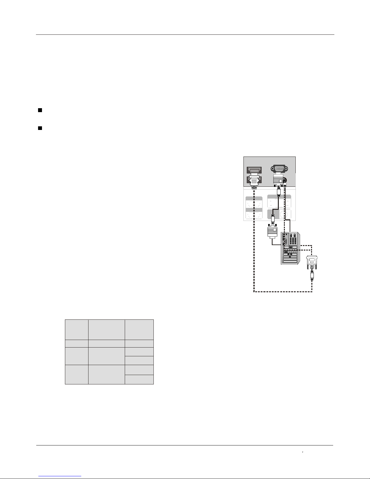
How to connect
1. To get the best picture quality, adjust the PC graphics card
to 1024
2. Use the TV`s PC or DVI (Digital Visual Interface)Audio IN
port for video connections, depending on your PC connector.
If the graphic card on the PC does not output analog and
digital RGB simultaneously, connect only one of either PC
r HDMI/DVI IN to display the PC on the TV.
If the graphic card on the PC does output analog and digital
RGB simultaneously, set the TV to eithe DVI;
(the other mode is set to Plug and Play automatically by the TV.)
3. Then, make the corresponding audio connection. If using a
sound card, adjust the PC sound as required.
How to use
1. Turn on the PC and the TV.
2. Turn on the display by pressing the POWER button on the
TV's remote control.
3. Use INPUT on the remote control to select PC o r HDMI/DVI
source.
4. Check the image on your TV. There may be noise
associated with the resolution, vertical pattern, contrast or
brightness in PC mode. If noise is present, change the PC
mode to another resolution, change the refresh rate to
another rate or adjust the brightness and contrast on the
menu until the picture is clear. If the refresh rate of the PC
graphic card can not be changed, change the PC graphic card
or consult the manufacturer of the PC graphic card.
Note
1.Use a DVI cable.
2.Avoid keeping a fixed image on the TV's screen for a long
period of time. The fixed image may become permanently
imprinted on the screen.
3. The synchronization input form for Horizontal and Vertical
frequencies is separate.
x768 .
IN
o
r PC or HDMI/
Resolution
Frame
frequency
(Hz)
VGA
SVGA
XGA
640*480
60Hz
800*600
1024*768
60Hz
Mode
Resolution
External Equipment Connections
Installation
75Hz
PC connection
Owner s Manual 13
60Hz
75Hz
 Loading...