

Page 1
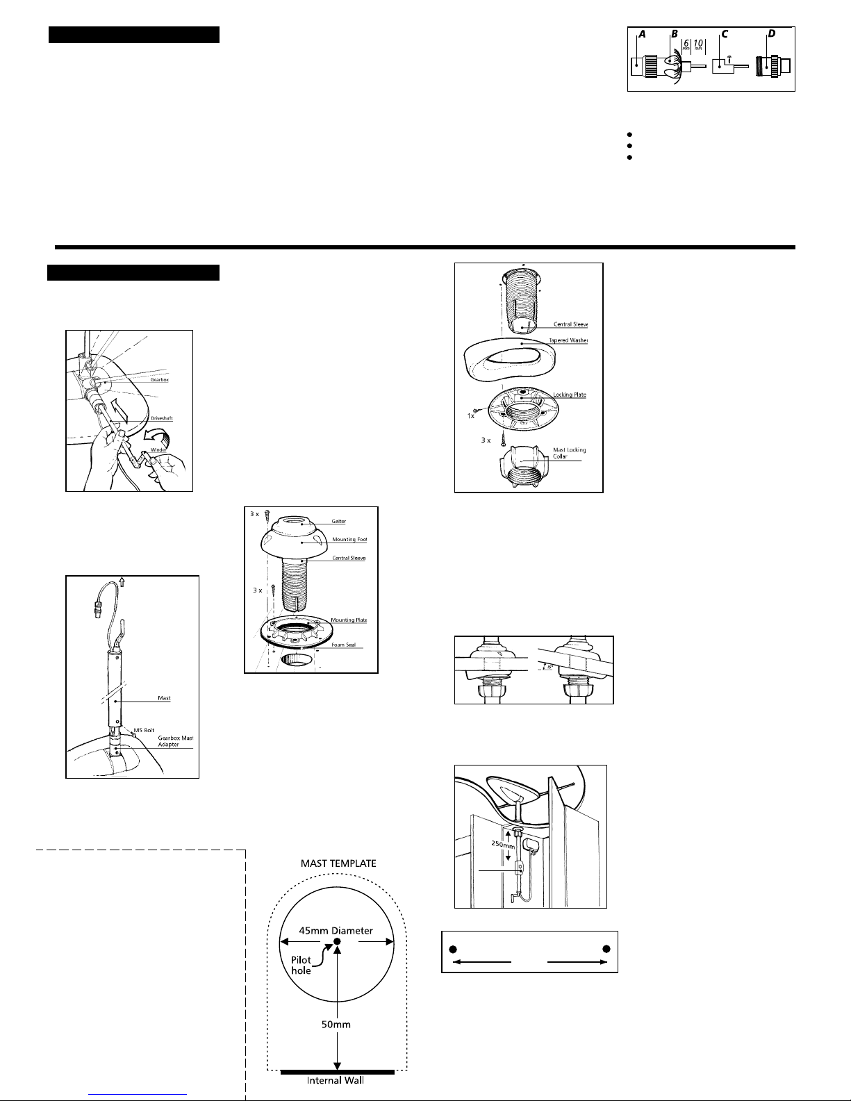
Connecting the Coaxial TV Plug
Should the coaxial plug need to be removed, please
note how it comes apart and reassemble as follows:-
1. Prepare the cable by removing 16mm of white
outer sheath to expose the braided copper wire.
2. Next, remove 10mm of the exposed braided
copper wire and the central air-spaced insulation to
expose the single central core.
3. Feed the screw cap A and the pronged clamp B
over the cable. Pull back evenly the copper
braiding over the pronged clamp as shown below.
IMPORTANT IT IS CRITICAL THAT NONE OF
THE COPPER BRAIDING IS TOUCHING THE
CENTRAL CORE.
4. Push on item C up to B and secure the central
core by tightening the small grub screw. Be careful
not to over tighten, which could sever the wire.
5. Screw A and D together to complete the
assembly.
ASSEMBLY & INSTALLATION
Assembling the Mast & Antenna
1. Taking the drive-shaft, insert it into the gearbox and
rotate anti-clockwise until the Gearbox Mast Adapter
has rotated through 90
0
and is vertical.
Routing the Coaxial cable
Coaxial Cable is quite fragile and must be handled with
care. Please comply with the following as failure to do
so will severely affect performance.
1. Should the coaxial plug be removed, it is very
important that it is refitted correctly as described
below.
2. Do not crush, kink or over-bend the coaxial cable
which has a minimum bend radius of 25mm.
3. Any excess cable should be removed and MUST
NOT be coiled.
IMPORTANT GUIDELINES
FM Radio Connection
Status is designed to receive FM radio when connected to a
car-style radio.
1. This will require a coaxial car radio plug, a coaxial plug
and a length of coaxial cable, which are available from
our Vision Plus Range.
2. Once the cable has been installed, plug into the TVFM socket of the Power Pack and into your Radio.
IMPORTANT You DO NOT need to extend the telescopics
for FM radio reception.
Operating the System
Firstly determine the approximate location of the nearest
transmitter and whether the signals are horizontally or
vertically polarised. For assistance ask your site operator or
check other antennas in the vicinity.
1. Loosen the Mast Locking Collar and Wall Bracket* and
raise the antenna. Turn the mast to direct the Antenna
towards the TV transmitter.
The RED SPOT on the bottom of the mast indicates the
front of the Antenna.
2. When receiving vertically polarised signals, rotate the
Winder anti-clockwise to cant the antenna through 900.
DO NOT over tighten or use undue force on the winder.
DO NOT cant for vertically polarised signals with the
TELESCOPICS EXTENDED
3. Switch ON the Power Pack and the red LED will
illuminate.
4. Check the gain control switch is set to normal - NML.
See Problem 2, over the page for use.
5. Tune your Television into the strongest signal. You may
need to adjust the direction of the mast to achieve the
best picture quality.
6. Secure by tightening the Mast Locking Collar and Wall
Bracket*.
VHF Television Reception (Overseas Only)
1. Extend the two telescopic antennas.
2. Tune your Television into the strongest signal. You may
need to adjust the direction of the Antenna to achieve
the best picture quality.
3. For fine tuning of VHF you may also need to adjust the
length of the telescopics.
IMPORTANT VHF TV transmissions are ONLY
horizontally polarised.
Removing the Antenna
A permanently fitted Status can be easily removed leaving
only the Mounting Foot and rubber gaiter.
1. Unplug the antenna from the Power Pack.
2. Loosen the Mast Locking Collar and Wall Bracket and lift
off whilst feeding out the mast and cable.
3. Push the Blanking Cap supplied into place.
IMPORTANT - The Blanking Cap is a temporary seal and
is not recommended for long term use.
2. Using the Allen Key unscrew the M5 pozi-pan bolt from
the Gearbox Mast Adapter.
3. Lower the mast over the coaxial cable and drive-shaft
and gently push the mast over the three O-rings with a
twisting motion being careful not to trap or damage
the O-rings. If necessary use a soapy water solution as
a lubricant (DO NOT use oil based lubricants).
VERY IMPORTANT - When refitting the M5 bolt,
the head must be flush with the mast to prevent
damage to the gaiter.
IMPORTANT - Ensure the cable and drive-shaft are
NOT twisted, but run along side each other.
Angle Adjustment.
The Mounting Foot is designed to pivot on the Mounting
Plate to allow for level fixing on a sloping surface.
1. To adjust, twist the Central Sleeve around inside the
gaiter until the direction of tilt lines up with the line of fall
of the roof and the screw holes in the Mounting Plate.
2. When drilling the hole for the mast, you must ensure the
tapered washer does not foul on the wall. You may need
to adjust the template to ensure the hole is in alignment
with the Wall Bracket*.
3. When tightening the Tapered Washer and Locking Plate,
you must ensure the mast sits VERTICAL when in position
and aligns with the Wall Bracket*
The Power Pack
Positioning & Fixing
1. Locate the Power Pack in the wardrobe or locker near
the mast, where it is easily accessible.
4. Position so that the Antenna Dome is not shielded from
incoming TV signals when raised.
Fitting
The Wall Bracket is only supplied with the
530/10 long mast model.
The Mounting Foot tilts, which enables the mast to remain
vertical on a sloping surface of up to 150. If your roof is
angled, refer to Angle Adjustment below.
1. Position the centre of the hole for the mast 50mm from
the wall. Alternatively offer the template up to the ceiling
against the wall and drill a VERTICAL 45mm diameter
hole.
2. On the roof, screw into place the Mounting Plate and
foam seal with the three 16mm screws supplied.
3. Guide the Mounting Foot and Central Sleeve into place and
fix with three 32mm screws supplied.
4. Inside the wardrobe, thread the Locking Plate and Tapered
Washer up the Central Sleeve to the ceiling and hand
tighten. Secure with the three 16mm screws ensuring the
Central Sleeve is VERTICAL.
5. Once the Locking Plate is in position, tighten the cross
screw onto the Central Sleeve to prevent rotation and thread
the Mast Locking Collar onto the end of the Central Sleeve.
6. When installing a 530/10, position the Wall Bracket 250mm
down from the ceiling, securing in place with the four 38mm
screws supplied.
Positioning
When positioning the Antenna & Mast, please consider the
following:-
1. Position in a suitable wardrobe or locker, against an
internal wall, away from the edge of the roofline to
reduce the possibility ofdamage when travelling.
2. Wherever possible, mount on the offside of the
vehicle to reduce the possibility of collision with
overhead obstructions.
3. You must ensure there is enough space for the mast
to retract fully and for the location of the Power Pack.
7. Feed the coaxial cable and mast through the Mounting
Foot and Wall Bracket* and lower into place.
8. Tighten the Mast Locking Collar and the Wall Bracket
to secure the mast.
It is crucial that the mast runs VERTICAL.
Power Pack Template for fixing holes
59mm
DO NOT connect into any other 12 volt power cables as they
may carry electrical interference which will cause picture
distortion.
2. Fix in place using the two 16mm screws.
Wiring to Power Supply
1. Status requires a 12-24 volt power supply from a fused
auxiliary outlet fed from the battery. If wiring direct to a
battery we recommend an in-line fuse (max 5 amp) on
the positive wire. If unsure please consult with a
qualified installer.
RED STRIPE +VE, BLACK VE
3. Plug the Antenna into the ANT.IN socket. DO NOT
secure the cable, which must be left loose.
4. Status is supplied with a 2 metre lead to connect your
TV to the Power Pack. However, if your TV position is a
greater distance, you will require a length of coaxial
cable and two coaxial plugs, which are available from
our Vision Plus Range.
5. Plug your TV lead into the TV-FM socket of the Power
Pack and into your TV antenna socket.
IMPORTANT When removing cables from the Power
Pack, DO NOT pull on the cable, only the plug.
Connecting Up the System
1. Depending on the Power Pack location, it may be
necessary to shorten the cable from the Antenna to the
Power Pack - DO NOT COIL ANY EXCESS CABLE.
2. Trim the cable and refit the Coaxial Plug as in Important
Guidelines above. Be very careful at this stage.
IMPORTANT- It is crucial to ensure there is enough cable
to raise the mast fully without stretching or kinking the
coaxial cable.
#
Wall Bracket*
* Only the 530/10 comes with the additional Wall Bracket
2 YEAR GUARANTEE
PLEASE COMPLETE AND RETURN TO:
Grade UK Limited,
Finch Close,
Lenton Lane Industrial Estate,
Nottingham NG7 1NN.
530 Buckleys
#
The Status 530/10 can only be fitted
where the Wall Bracket can be fixed to a
vertical surface.
The Status 530/5 should only be fitted
if there is extra strength in the roof, such as a
support or block.
The RED SPOT on the bottom of the mast
indicates the front of the Antenna.
Travelling
DO NOT TRAVEL:-
With the Antenna raised
With the Antenna set for vertical signals
With the Telescopics extended
When travelling adjust the antenna so that it points
to the rear of the vehicle to reduce the possibility of
damage when travelling.
4. Avoid increasing the number of connections or
breaks in the coaxial cable as they will reduce
performance, especially in weak signal areas.
5. Do not run coaxial cable next to mains cable, leave a
minimum distance of 120mm to prevent
interference.
6. Do not allow the cable to come into contact with
any hot surfaces as this could melt the air-spaced
insulation of the cable.
7. Keep away from fluorescent lighting.
8. When installing the coaxial cable, Do not feed
through by pulling on the coaxial plug.
9. Do not add excessive lengths of coaxial cable.This
will result in increased signal losses and a reduction
in picture quality.
10. Should the cable need to be lengthened, use only
RF100 specification cable and high quality coaxial
plugs and couplers which are available from our
Vision Plus range through our dealers or directly
from ourselves.
Page 2
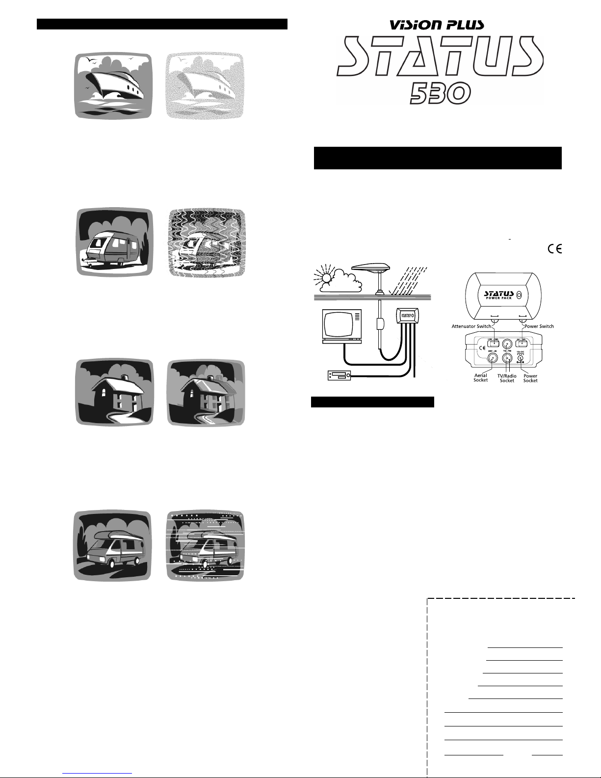
1. Weak TV Signal
This produces a Snowy picture which can be caused if you are too far away from the TV
transmitter, such as in a remote area, positioned in a valley, or if there is a building, hill or other
obstruction blocking the signal.
Each TV transmitter has a defined service area where reception will be good. Beyond that
boundary is a fringe area where the TV signal will be weaker and the reception quality poorer.
Remedy
Firstly determine whether you are in a poor reception area. Secondly check the points covered in
Fault Finding .
2. TV Signal too strong
This can produce severe picture distortion like a zig-zag style pattern. This can be caused when
you are too close to a transmitter or picking up strong radio transmissions from another source
such as CB radio. Also electrical interference can cause similar effects (see Interference 4 below).
Remedy
Turn the gain control switch on the Power Pack to LO. Secondly check the points covered in Fault
Finding.
3. Ghosting
This is the type of picture you will see when the TV signal is reflected from something in your
locality. The something may be a local building or landmark. Your antenna is receiving both the
direct signal and the reflected signal from the same transmitter.
Remedy
Adjust the direction of the antenna or try to move to a better position away from the obstruction.
Unfortunately it may not always be possible to isolate your antenna from the cause of the
problem.
4. Electrical Interference
The above pictures demonstrate a typical example of electrical interference. This type of interference is commonly caused by electrical appliances, such as fans, electric shavers, fluorescent lights.
Other forms of interference can produce a zig-zag pattern similar to that described in Interference
2 which may be caused by inverters, charging units etc.
Remedy
Check the points covered in Fault Finding. In some instances, this type of interference can be
overcome by switching off the relevant appliances.
DIRECTIONAL
TELEVISION & FM RADIO ANTENNA
Installation and Operation Guide
Please read these instructions carefully. Incorrect
installation will affect the performance of your Status
Dimensions:
Antenna Dome Length 530mm
Width-telescopics in 340mm
width-telescopics out 1045mm
Mounting Foot Diameter 122mm
Height Overall 150 mm
Height No Antenna Dome 50 mm
Power Pack 115 x 70 x 50mm
COMMON INTERFERENCE PROBLEMS & POSSIBLE REMEDIES
04-3000/5 Model 485mm mast 2m Coaxial cable
04-3000/10 Model 920mm mast 5m Coaxial cable
Frequency Range UHF 470-860 MHz
VHF 40 -230 MHz
FM 88 -108 MHz
Antenna Forward Gain 7db
Amplifier Gain 18 db*
Gain Adjustment 15 db
Flatness
±
1.5 db
Noise Figure 3 db
Output Impedence 75 ohms
Output 98 dbuv
Power Supply 12-24 v DC
Power Consumption 35 ma
TV lead 2 metres
the ANT-IN socket. If the LED then illuminates the fault lies
with either the coaxial plug or the coaxial cable, please refer
to these areas described earlier.
If the LED is still not lit, please contact our office for further
assistance.
Short Hook Up Test
This test isolates parts of your system leaving only the TV and
the Status antenna linked directly together.
Firstly, unplug the coaxial plugs from the TV-FM sockets of
the Power Pack which will be connected to a TV outlet
socket.
With your TV fly lead, connect your TV direct to the Power
Pack, plugging into one of the TV-FM sockets.
Ensure the antenna dome is plugged directly into the ANT-IN
socket of the Power Pack and switch on. Tune in your TV for
the strongest signal.
If the picture quality is improved the fault lies with the wiring
of the system between the Power Pack and the TV outlet
socket.
Antenna Dome Coaxial Cable
Check the routing of the coaxial cable from the Antenna
Dome to the Power Pack. Check to ensure there are no kinks
or trapped cable or if there are loops of surplus cable which
could be affecting performance.
Customer Help Line
Should you still be experiencing difficulties and require
assistance, please do not hesitate to contact us at
the address below.
FAULT FINDING
The following are some of the key areas we suggest you check
which generally solve the most common problems encountered with the operation of the Status antenna.
Coaxial Plugs
It is critical that all coaxial plugs in the system are fitted
correctly. Using the diagram and procedure described over the
page, please check each individual plug, ensuring it is wired
correctly. Secondly please ensure only quality plugs have been
used.
Coaxial Cable
Sharp bends, kinks and hot surfaces can easily damage coaxial
cable and should be avoided. An inspection of the cable
routing is recommended to ensure all is correct. Coaxial cable,
if placed in close proximity to electrical cables, transformers or
other pieces of electrical equipment, may pick up electrical
interference causing picture quality to deteriorate, especially in
poor reception areas. Excess cable should be removed and
NOT coiled as this may cause picture distortion.
Gain Switch
Situated below the LED light on the Power Pack, this switch
should be set to the normal NML (switch UP) position for
general use. The Low setting may be used when situated
close to TV transmitters where strong signals may be affecting
the quality of the picture. (see Interference2 below)
Red LED Light
Should the red LED on the Power Pack not light, first try
unplugging the cable connected to the Antenna Dome from
Buckleys Caravans
St Josephs Road
Mallow
County Cork
Ireland
T: 022 22157
F: 022 43364
#
12 - 24vDC
*
Gain figures must not be judged in isolation. A greater figure does
not mean a better picture. Status is designed for optimum
performance
Conforms to the European Directive
89/336/EEC
Purchase Date
Serial Number
Dealer Name
Your Name
Address
Postcode
2 YEAR GUARANTEE
 Loading...