

Page 1
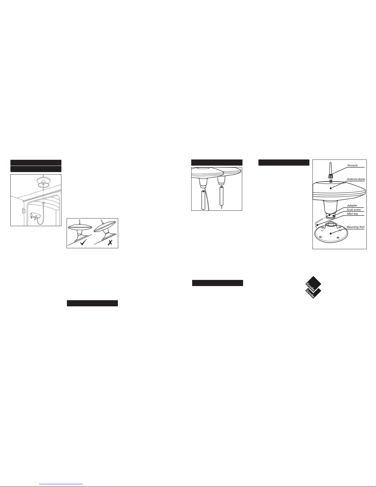
Positioning
When positioning the Antenna Dome
please allow for the following:-
1.
Place above a wardrobe or locker to
provide
a suitable location for the
Power Amplifier below.
2. Position as high as possible to ensure
Status is not shielded from incoming
signals.
3. Do not place within one metre of
any metal protrusions such as roof
racks, metal flues, metal poles etc. as
this may cause picture distortion.
4.
On a Caravan or Motorhome mounting
on
the offside will reduce collision
with overhead obstructions.
Fixing
1. Make a hole 15mm in diameter, large
enough for the coaxial cable with plug
fitted to be passed through, making
sure there are no sharp edges that
could cut or chafe the cable.
2. Remove the Mounting Foot from the
Antenna Dome. Turn the Mounting
Foot
upside down and with a SEALANT
ADHESIVE
fill the channel around the
edge, including around the holes for
the fixing screws.
The Antenna Dome
Pole Fitting
INSTALLATION
IMPORTANT - The channel needs to be
slightly over-filled to ensure a good contact.
3. Place in position centrally over the
drilled hole and secure with the four
16mm self tapping screws.
4.
Once the sealant has set, thread the
coaxial
cable through the roof, pulling
through
the cable as the antenna is
lowered, making
sure the cable does
not snag, kink, chafe or become
trapped.
5. Push the Antenna Dome into position,
ensuring it is properly seated in the
Mounting Foot. Secure by tightening
the two grub screws with the Allen
Key.
Angle Adjustment.
Only relevant if you are mounting Status
on a sloping surface. Level fixing is very
important to ensure optimum performance.
1. To adjust the angle, remove the Antenna
Dome from the Mounting Foot and
turn the Antenna Dome upside down.
2. With a screwdriver loosen the Central
Bolt, adjust the Adapter to the desired
angle and re-tighten the central bolt.
3. Push the Antenna Dome into position,
ensuring it is properly seated in the
Mounting Foot. Secure by tightening
the two grub screws with the Allen
Key.
The Power Amplifier
Positioning & Fixing
1. Locate the Power Amplifier in the
wardrobe
or l
ocker below the Antenna
Dome where it
is easily accessible and
where possible close to the TV position.
2. Fix in place using the two 38mm
screws
Wiring to Power Supply
1.
Status requires a 12-24 volt power
supply
from a fused auxiliary outlet fed
from t
he battery. If wiring direct to a battery
we
recommend an in-line fuse (max 5
amp)
on the positive wire. If unsure
please consult with a qualified installer.
RED STRIPE +VE, BLACK –VE
DO NOT connect into any other 12 volt
power cables as they may carry electrical
interference which will cause picture
distortion.
Connecting the Antenna
1. Shorten the cable from the Antenna
Dome to the required length to reach
the Power
Amplifier - DO NOT COIL ANY
EXCESS CABLE
.
2. Trim the cable and refit the F-Connector
as described in this guide.
3. Once fitted, connect the Antenna to the
‘ANT.IN’ socket.
DO NOT secure the cable with any staples or ‘P’
Clips as this may damage the cable, it is best
left loose.
Connecting to your Television
To connect to your television you will need
to run a cable to your TV position to the Power
Amplifier. There are many options available
dependant on
your particular installation.
You may well require additional cable,
connectors, plugs or sockets which are
available from ourselves or through your
local dealer.
Whenever routing the cable or fitting
connectors please follow our Important
Guideline below.
Operating the System
1. Switch ON the Power Amplifier and the
blue LED will illuminate.
2. Check the gain control switch is set to
maximum by rotating clockwise.
3. Turn on your television set and tune in.
This may be necessary at all new
locations.
1. Remove the Mounting Foot from the
Antenna Dome.
2. The Adapter is now ready to
accommodate any 25mm pole, such
as those in the Vision Plus Range.
3. The coaxial cable can be threaded
down the centre or outside of the
pole.
4. If the cable is being fed down the
outside please ensure that the top of
the pole does not rub or cut the
coaxial cable when being pushed into
place.
5. Once the pole is in place, secure by
tightening the two grub screws with
the Allen key.
IMPORTANT – Status is not designed to be
used in conjunction with a ‘through-theroof’ pole kit.
Removing the Antenna
A permanently fitted Status may be
removed if there are severe height
restrictions, leaving only the Mounting Foot
in place.
1. Disconnect the Antenna from the Power
Amplifier. On the Adapter loosen the
two grub screws with the Allen key
and lift off whilst carefully feeding out
the coaxial cable with plug attached.
2. Push the Blanking Cap supplied into
place to cover the central hole.
This may be necessary should you wish to
reduce the overall height of the antenna by
90 mm.
1. Simply unscrew the Pinnacle and
remove. The antenna is designed to
remain water tight without the
Pinnacle.
2. To replace, simply screw in and tighten
BY HAND.
3. IMPORTANT - The Pinnacle is an
integral part of the antenna and
critical
to its performance. When in
use always ensure the Pinnacle is fitted.
Removing the Pinnacle
Grade UK Limited
8 FinchClose
Lenton Lane
Nottingham NG7 2NN
Tel: 0115 986 7151
email: [email protected]
www.gradeuk.co.uk
Page 2
Routing The Coaxial Cable
Coaxial Cable is quite fragile and must be handled
with care. Please comply with the following as
failure to do so will severely affect performance.
1.
Should the coaxial plug be removed, it is very
important that it is refitted correctly as
described below.
2. Do not crush, kink or over-bend the coaxial
cable, which has a minimum bend radius
of 25mm.
3. Any excess cable should be removed and
MUST NOT be coiled.
4.
Avoid increasing the number of connections
or breaks in the coaxial cable as they will
reduce performance, especially in weak
signal areas.
5. Do not run coaxial cable next to mains
cable, leave a minimum distance of 120mm
to prevent interference.
6. Do not allow the cable to come into contact
with any hot surfaces as this could melt the
air-spaced insulation of the cable.
7. Keep away from fluorescent lighting.
8. When installation the coaxial cable, Do not
feed through by pulling on the coaxial plug.
9.
Do not add excessive lengths of coaxial cable,
this will cause increased TV signal losses.
10. Should the cable need to be lengthened, use
only RF100 specification cable and high quality
coaxial plugs and couplers which are
available from our Vision Plus Range through
our dealers or directly from ourselves.
IMPORTANT GUIDELINES
Connecting an F-Connector
Should the F-Connector need to be removed,
please note how it comes apart and reassemble
as follows:-
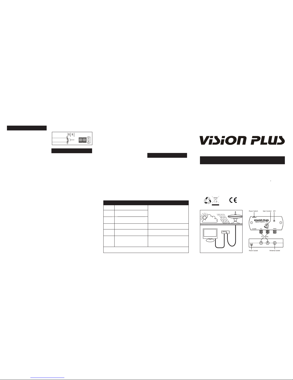
1. Remove 10mm of white outer sheath.
2. Pull back evenly the copper braiding.
3. Remove 6mm of the insulation.
4. Screw the F-connector on to the cable.
Keep turning until the central insulation
is flush inside the plug
STATUS 330 - Digital Antenna
User Guide
Please read these instructions carefully. Incorrect
installation will affect the performance of your Status
Technical:
04/2075/5 Model - Coaxial cable 5 metres
04/2075/10 Model - Coaxial cable 10 metres
Diameter - Antenna Dome 315mm
Diameter - Mounting Foot 185mm
Height Overall 280 mm
No Pinnacle 180 mm
No Antenna Dome 50 mm
Power Amplifier
115 x 46 x 28mm
Frequency Range UHF 470-860 MHz
Amplifier Gain 18 db
Gain Adjustment - Min 15 db
Flatness
+
1.5 db
Noise Figure 2.8 db
Output Impedence 75 ohms
Output 98 dbuv
Power Supply 10.8-28 vDC
Power Consumption 55 ma
RETAIL VP2
FAULT FINDING
The following are some of the key areas we
suggest you check which generally solve the most
common problems encountered with the operation
of the Status antenna.
Coaxial Connections
It is critical that all connections in the system are
fitted correctly. Using the diagrams and procedure
described over the page, please check each
individual plug ensuring it is wired correctly.
Secondly please ensure only quality plugs have
been used.
Coaxial Cable
Sharp bends, kinks and hot surfaces can easily
damage coaxial cable and should be avoided. An
inspection of the cable routing is recommended
to ensure all is correct. Coaxial cable, if placed in
close proximity to electrical cables, transformers
or other pieces of electrical equipment, may pick
up electrical interference causing picture quality
to deteriorate, especially in poor reception areas.
Excess cable should be removed and NOT coiled
as this may cause picture distortion. An inspection
of the routing of the cable is highly recommended
to ensure all is correct.
Pinnacle
The pinnacle is essential for the optimum
performance of the antenna and therefore should
be in place when the antenna is in use.
Gain Control
In normal use the button should be rotated clockwise
for maximum gain. In strong signal areas the
amplification can be reduced by rotating the button
anti-clockwise until picture quality improves. The
button rotates through 270 degrees from MAX to MIN.
LED Light
Should the LED on the Power Amplifier not light,
firstly check there is power to the unit. Secondly
check the polarity is correct. Otherwise contact
ourselves for further assistance.
By-Pass Tests
There are two tests that enable you to isolate
parts of your installation. You will require the
Coaxial/F-Connector adapters supplied in the
small labelled bag.
1. Firstly, disconnect the cables from the ‘TV’
sockets of the Amplifier. These are connected
to a TV outlet socket. Attach one of the
adapters supplied to your TV fly-lead and
connect your TV direct to the Amplifier,
plugging into one of the ‘TV’ sockets
Ensuring the Antenna Dome is plugged into
the ‘ANT-IN’ socket, switch on and tune in
your TV for the strongest signal. If the
picture quality improves the fault lies with
the wiring of the system between the
Amplifier and the TV outlet socket.
2. Secondly bypass the Amplifier by removing
the Antenna’s cable from the ‘ANT-IN’ and
using the second Adapter plug the Antenna
directly to your TV. If the picture quality is
improved the fault lies with the Amplifier.
Antenna Dome Coaxial Cable
Check the routing of the coaxial cable from the
Antenna Dome to the Amplifier. Check to ensure
there are no kinks or trapped cable or if there are
loops of surplus cable which could be affecting
performance.
Spares & Repairs
Should you require any parts for replacement or
repairs please log on to www.gradeuk.co.uk or
contact ourselves on 0115 986 7151.
Two Year Guarantee
The Status antenna has a return to base
guarantee against defective parts and workmanship
for the two years from date of purchase. This
does not include any malfunction resulting from
improper use, accidental or malicious damage.
To support your guarantee claim a dated Proof of
Purchase will be required.
This does not affect your statutory rights. Any queries concerning
warranty please contact ourselves.
MAINTENANCE
RoHS
Signal
Symptom
Action
No picture or sound, TV freezing, severe
pixilation, break up and picture drop out
Moderate pixilation and sound distortion
Minor pixilation, will not receive all
channels
Stable picture, good sound quality, will
receive all channels
Moderate pixilation, picture break up and
drop out
No picture or sound, TV freezing, severe
pixilation, break up and picture drop out
Check the amplifier gain is set to Maximum.
Bypass the amplifier by connecting your antenna
directly to your TV to confirm that the amplifier is
operational.
N / A
Reduce the amplifier gain (rotate anti-clockwise).
Bypass the amplifier by connecting your antenna
to your TV.
Very Poor
Poor
Medium
Good
Strong
Very Strong
After performing any of the ‘Actions’ above you must re-tune your TV
When the Antenna Dome was originally fitted
and lowered onto the Mounting Foot, cable may
have been trapped or kinked under the Mounting
Foot. To check remove the Antenna Dome as
described over the page to see if this has occurred.
Customer Help Line
Should you still be experiencing difficulties and
require assistance, please do not hesitate to
contact us at the address below.
IMPORTANT – The copper braiding MUST NOT
TOUCH the central wire.
 Loading...