

VisionMaster VM-6104-1080P User Manual

VM-6104-1080P MDVR User Manual
VM-6104-1080P User Manual
1/67

VM-6104-1080P MDVR User Manual
Catalogue
1.Introduction..................................................................................................错误!未定义书签。
1.1.Intention............................................................................................................................... 3
1.2.Attention...............................................................................................................................3
2.Product Description........................................................................................................................4
2.1.Product Main Functions......................................................................................................5
2.2.Product Parameters.............................................................................................................6
2.3.Products Appearance Features.......................................................................................... 9
2.3.1.Overall Look.............................................................................................................. 9
2.3.2.Product Dimension and Installation Position........................................................9
2.3.3.Front Panel Interface and Indicator Lights............................................................ 9
2.3.4.Rear Panel Interface and Descriptions................................................................. 10
2.4 Connector Drawing............................................................................................................11
3. Installation direction...................................................................................................................12
3.1 Host installation steps.......................................................................................................12
4. USB Tools & MDVR APP User-Guidance.................................................................................... 15
4.1 USB Tools:...........................................................................................................................15
4.2 MDVR Assistant................................................................................................................. 15
4.2.1 MDVR Assistant: ................................................................................................... 15
4.2.2 App Download........................................................................................................ 15
5.MDVR Operation Guidance.......................................................................................................... 18
5.1 Remote Controller Function Buttons Descriptions........................................................18
5.2 The user login.................................................................................................................... 19
5.3 System operation and setup............................................................................................. 20
6.FAQ................................................................................................................................................. 54
6.1 Quick setting...................................................................................................................... 54
6.1.1Connect cable test and start MDVR....................................................................... 54
6.1.2MDVR quick upload files to platform.................................................................... 55
6.1.3 Vehicle Info & Add Vehicle..................................................................................... 56
6.1.4 Vehicle Edit..............................................................................................................57
6.1.5 IO serial use.............................................................................................................58
6.1.6 PTZ connection and setting...................................................................................59
6.2 Record video file size.........................................................................................................59
7.Platform Operation.......................................................................................................................60
7.1 iCTMS Platform Management Functions:........................................................................60
1. iCTMS: Location............................................................................................................60
2.iCTMS: Video.................................................................................................................. 61
3.iCTMS: Track Playback..................................................................................................62
4.iCTMS: Video Playback..................................................................................................62
5. iCTMS: Statistics........................................................................................................... 62
6. iCTMS: Operations........................................................................................................ 63
6.1 Vehicle Info & Add Vehicle........................................................................................64
8. Related questions.........................................................................................................................65
2/67

VM-6104-1080P MDVR User Manual
1.1.Intention
《 VM-6104-1080P series products user manual 》 writing intention is enable
users to master the features and functions of this product with the help of this
manual, the product can be correctly installed and used. At the same time, it is
beneficial to the technical support colleagues' daily work and easy for product
engineers to maintain the product.
1.2.Attention
In order to enable users to use this series of products for a long time, safely
and satisfactorily, please read the following warnings before installing and
using the products:1. All installation and maintenance must be performed by
professional technicians
2. The normal working voltage range of the device is DC 8V~36V. Please note
that the power input should not be connected and the stability of the power
input line. The output cannot be short-circuited.
3. The device outputs 12V external voltage, which is only used for camera power
supply. It is not allowed to connect any non-recommended equipment.
4. Connect the ground wire of the correct connection device to the ground wire
of the vehicle to form a circuit.
5. The equipment should be installed in a dry and ventilated environment to
avoid moisture, rain and vehicle cleaning and flushing position, keep the
equipment away from heat, dust and strong magnetic field.
6. Please install the equipment as far as possible on the vehicle where the
vibration is weak, improve the stability of the equipment and prolong the service
life.
7. Do not stack debris within 20cm around the installation equipment, and do
3/67

VM-6104-1080P MDVR User Manual
not have heavy objects pressed to ensure the heat dissipation environment.
8. The storage devices and modules on the device do not support hot swap. Do
not insert or remove storage devices or modules while the device is powered on.
9. Please perform regular maintenance on the storage device hard disk or SD
card: copy the video data to the computer and format it to protect and extend
performance and service life of the storage device.
10. Do not open or disassemble the equipment without the guidance of a
professional technician.
1.3.Products Advantages
Full HD 1080P resolution(120fps NTSC/100fps PAL)
Power failure protection
Rich ports(4G,GPS,I/O,RS232,RS485,Canbus)
Large storage(2xSD card max 512GB,one SSD max 512GB)
Tools USB works with Tools APP to manage and set all devices in your cellphone
to replace Remote controller
Support extending connection with automatic passenger counting system or
ADAS&Driver Status Monitor Alert system
2.Product Description
The VM-6104-1080P series is a cost-effective, scalable device designed for
in-vehicle video surveillance and remote monitoring. Using high-speed processor
and embedded operating system, combined with the most advanced
H.265/H.264 video compression/decompression technology, network
technology and GPS/Beidou positioning technology in IT field. VM-6104-1080P
series products can realize 8CH AHD 1080P recording, optional
CIF/HD1/D1/AHD720P/ADH1080P multiple recording formats, local recording
and wireless data uploading car driving information record, and central software
can realize alarm linkage central Monitoring, remote management and playback
4/67

VM-6104-1080P MDVR User Manual
Functions
Description
Wireless
Communicati
on
Real-time remote monitoring, video downloading,
parameter configuration, remote upgrade, remote control
and other data communication through WIFI or 3G/4G
Recording
4ch/8ch AHD 1080P+1IPC(1080P) backward compatible
with ADH720P/D1/HD1/CIF
Support PAL system, NTSC system;
Video OSD overlay, such as time, channel name, license plate
number, GPS, speed...
Support storage device to record automatic coverage and
alarm video file protection
Storage
Support SSD+SD dual storage system to ensure not lose any
files
SSD max 512GB
SD card max 256GB*2
Playback
Support local 4-channel audio and video sync playback
Support PC-side playback analysis tool
Support remote search playback
Support traditional playback functions such as play, pause,
frame release, slow release, fast forward, fast reverse
Driving
Records
It can record driving information such as vehicle speed, GPS
data, temperature, and oil quantity;
analysis, dedicated to the expansion of the Internet of Vehicles.
VM-6104-1080P series products are simple and elegant, with super
anti-vibration, flexible installation, powerful functions and high reliability.
2.1.Product Main Functions
5/67

The switch quantity can be collected through the reserved 8
digital input ports;
Support local recording, view driving information
Support remote real-time upload and history search view
2.2.Product Parameters
Items
Device
Parameters
Descriptions
System
Operation
Linux3.10
Languages
Chinese/English/(Others can do
customization)
Control
Methods
Remote Controller、Platform、Tools APP
Video
Input
4 / 8xAHD1080P+1IPC
Output
1ch CVBS; 1ch HDMI
Signal
Standard
Electrical level: 1.0Vp-p Input / Output
impedance:75Ω NTSC/PAL(Option)
Audio
Input
8CH
Output
2CH
Signal
Standard
Electrical Level: 2.0Vp-p Input impedance:
4.7K Output impedance: 1.0K
Display
Image Pixel
PAL:704*576 ,NTSC:704*480
Terminal
External Display Monitor
Content
Live video; Date; Time; GPS information;
Communication signal; license plate; storage
information; network status
A/V
Compressi
on
Frame Rate
120fps 1080P @ NTSC / 100fps 1080P @ PAL
Recording
Mode
Boot, Timing, Alarm
Video
Compressio
n
H.265/H.264 , Variable bite rate ( VBR ) /
Constant bite rate(CBR)
Product Functions and Parameters List
VM-6104-1080P MDVR User Manual
6/67

VM-6104-1080P MDVR User Manual
Items
Device
Parameters
Descriptions
Resolution
1080P(1920*1080);720P(1280*720);D1
(704*576);HD1(704*288);CIF(352*288)
Audio
Compressio
n
G.726
Bit rate
32Kbps/40Kbps
Playback
Playback
Channel
Local single channel playback; browser 1/4/8
channel playback
Search
Mode
Time/Date, Channel, Alarm
Storage
SD Card
2xSD 2.0 Interface,support 256G SD card
SSD
1xSSD interface,support 512GB mSATA SSD
Flash
Memory
1Gb SLC Nandflash
Satellite
Position
GPS/BD
Frequency : L1 : 1575.42MHz B1 :
1561.098MHz
Sensitivity: Tracking:-165dBm Cold boot:
-148dBm
Cold boot time:<33s Warm boot time:6s
Accuracy: single positioning:3.0m(2DRMS)
SBAS:2.5m
Wireless
Transmissi
on
3G
EVDO/WCDMA/TD-SCDMA
4G
TD-LTE/LTE-FDD
WIFI
(optional)
Support 802.11 b/g/n(2.4GHz)
Support 802.11 ac(5GHz)
Function
Interface
USB
2xUSB 2.0 HOST
SIM/UIM
1xStandard SIM/UIM card slot
LAN
10M/100M/1000M
7/67

VM-6104-1080P MDVR User Manual
Items
Device
Parameters
Descriptions
CAN
1xCAN
Serial
Interface
1xRS485,2xRS232
Vehicle
Information
Collect
Status like speed, ignition, braking, back-off,
turn-left, turn-right, and etc.
Self-defined
I/O
8CH input、2CH output
Power
Input
DC8V ~ 36V
Output
12V@1A
Consumptio
n
< 9W (No peripheral)
Physical
Property
Working
Temperatur
e
-40℃ ~ +85℃
Working
Humidity
10% ~ 95%
Protection
Grade
IP43
Dimension
(L x W x H)
138 x 171 x 66mm
Weight
0.985Kg
8/67
VM-6104-1080P MDVR User Manual
Panel
Name
Description
Interface
SD1/SD2
SD card slot, 2 SD card loop recording
SIM
3G/4G sim card, 3G/4G dial-up Internet access
Indicator
Lights
Power
Red: the power light is bright when it detects
that there is input power.
REC
Green: Recording indicator light, the video light
is on when the device is recording, no video light
is off
SD1/SD2
Green: SD card indicator light, the light is on
when the SD card is detected, otherwise it is off.
4G
Green: 4G antenna exists, it’s on
GPS
Green: GPS antenna exists, it’s on
Alarm
Red: When there are alarm events, it blinks
IR
IR cable
interface
Receiving remote controller button
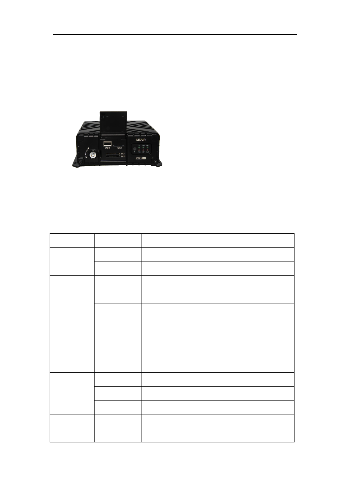
2.3.Products Appearance Features
2.3.1.Overall Look
2.3.2.Product Dimension and Installation Position
2.3.3.Front Panel Interface and Indicator Lights
9/67

Electrical
Lock
Electrical
Lock
SD card and SIM card bezel lock, can not be
activated without locking the host, open the lock
host automatically standby
2.3.4.Rear Panel Interface and Descriptions
Panel Interface
Description
AV
Out/AV—IN1~4
4-channel camera audio and video input interface;
1channel video output
AV—IN5~8
4-channel camera audio and video input interface;
ADAS
ADAS camera interface
DMS
DMS camera interface
USB
USB interface for video data backup
IPC
1 way IPC camera input interface
HDMI
Audio and video output interface
IO—COM—SPEE
D
8-channel IO alarm input, 2-channel alarm output; 1
RS485 interfaces,
2 RS232 interfaces; vehicle pulse speed interface
POWER
Power input interface, DC8-36V
GPS
GPS Antenna interface
4G Main
4G Main Antenna interface
4G Div
4G Division Antenna interface
WIFI/BT
WIFI Antenna interface
VM-6104-1080P MDVR User Manual
10/67
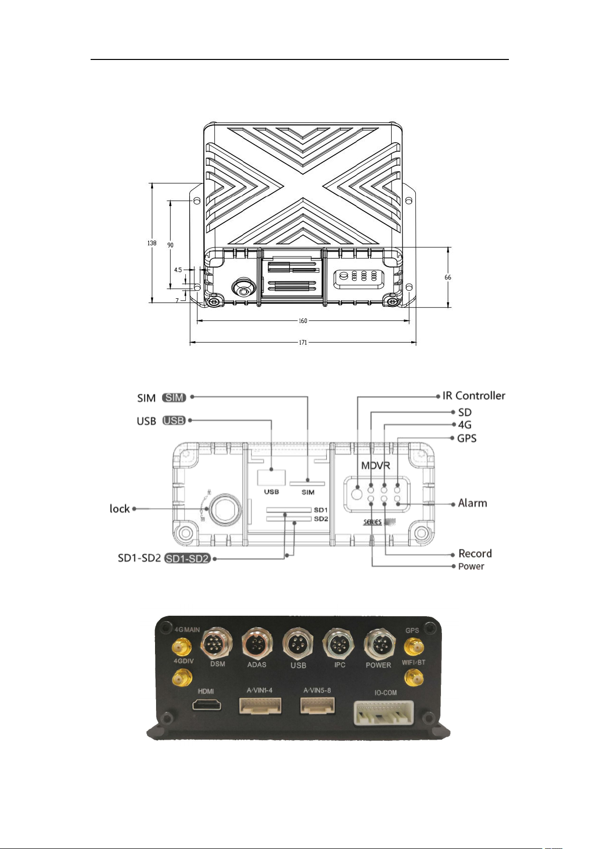
2.4 Connector Drawing
VM-6104-1080P MDVR User Manual
Host Dimension
Front panel structure
Rear panel structure
11/67

VM-6104-1080P MDVR User Manual
3. Installation direction
3.1 Host installation steps
Step1: Open the protective cover
Turn the counter clockwise to open the electronic lock on the front panel and
open the protective cover.
Step2: Install SIM and SD card
According to the panel identification, insert the SD card into the SD card slot
supporting 2*SD cards at the same time (the single card storage is not less 32GB);
Press the SIM card slot in place with the notch facing forward. Pay attention to
the front and back directions when inserting the SIM card. According to the
communication configuration of the device, the corresponding SIM card is
inserted, and 3G supports three different modes of WCDMA, EVDO and
TD-SCDMA. 4G supports TDD-LTE or FDD-LTE. (The machine supports single SIM
card by default)
Step3: Lock the electronic lock
After all the accessories are inserted(Including sim card, sd card), cover the
protective cover with the lower cover and turn the electronic lock clockwise to
close it. Otherwise, the device will not be turned on.
Step4: Install the host
The device supports 360 degree installation. Please install the device in a
suitable position in the vehicle according to the size of the counter hole bitmap.
(It is recommended that the user install it horizontally to ensure that the device
can work normally under extreme conditions. At the same time, consider the
waterproof, moisture-proof and lightning-proof protection of the main unit, and
prevent the vehicle from wash and damp, etc., causing the main board to burn
down.)
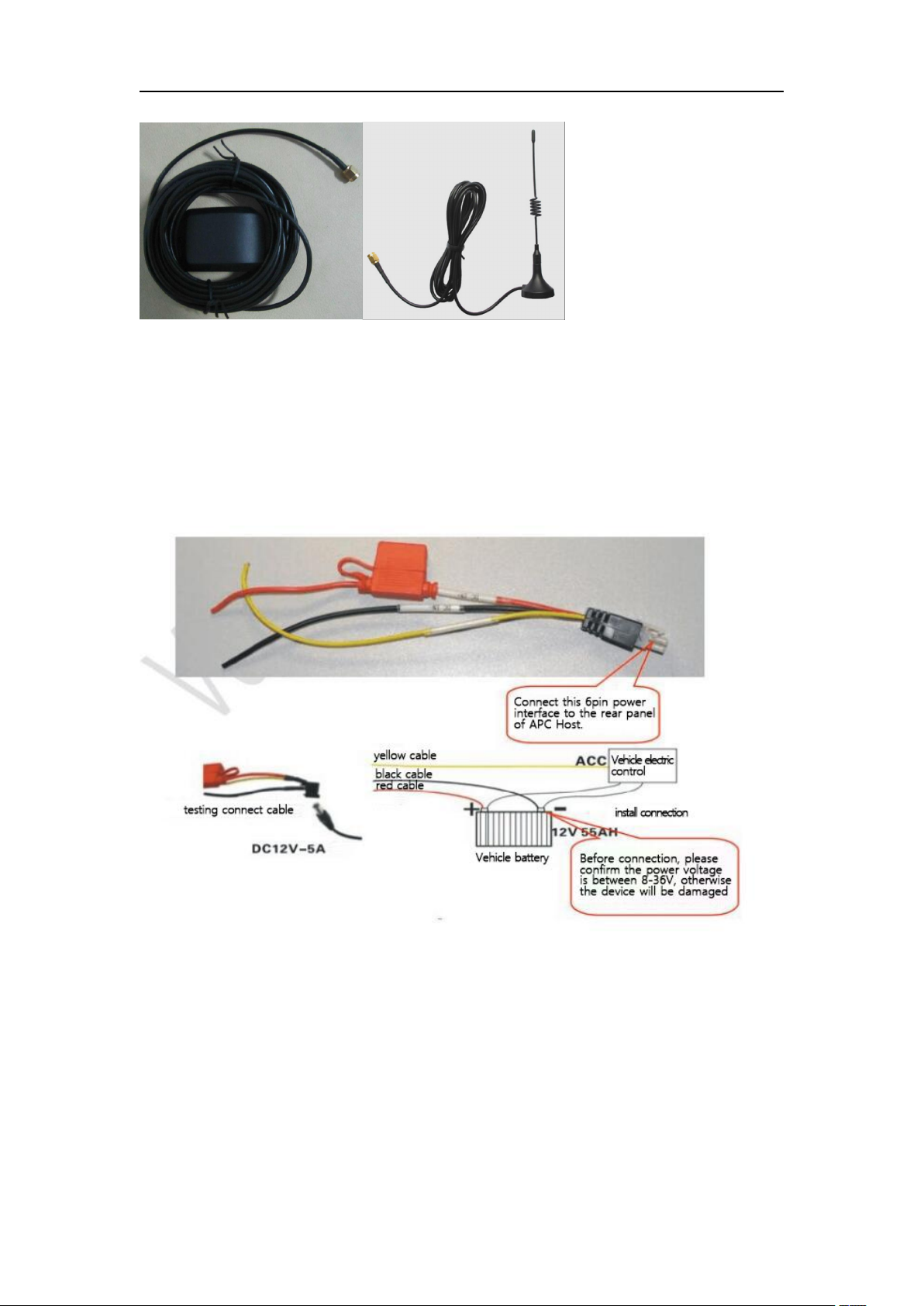
Step5: Install GPS, 3G/4G antenna
According to the configuration of the device, the GPS, 3G/4G, and WiFi antennas
as shown below are connected to the corresponding positions on the rear panel
of the counter, and reasonable wiring is performed to make various signal states
optimal and not susceptible to external interference.
12/67
VM-6104-1080P MDVR User Manual
Step6: Connect the power cord
Connect the 6PIN white plug to the 6PIN power input connector on the rear
panel of the counter. The red and black cables are directly connected to the car's
battery or to the level of the total power that has been insured. The red wire is
positive and the black is negative. The yellow wire is connected to the car ignition
wire ACC switch (that is the gear switch before the car starts the engine). When
the car key is turned on, the device will start working automatically, and if the
vehicle key is turned off, it will automatically turn off. As shown below:
Note:
1) Before connecting, you need to confirm that the voltage of the battery is
between 8V and 36V, otherwise it will burn out the equipment;
2) After connecting the wires, pay attention to the edges between the power
cables to prevent the power cables from short-circuiting and burning the battery
and other electrical equipment on the vehicle;
3) The yellow wire is recommended to be connected to the ignition wire,
otherwise the device will not support the shutdown delay and the power
consumption of the total power and reduce the life response;
4) The power cord of the counter is recommended to be directly connected to
13/67
VM-6104-1080P MDVR User Manual
the positive and negative poles of the vehicle battery, or after the battery is
connected to the fuse box, connect the positive and negative poles of the power
supply;
5) It is forbidden to connect to the metal conductor in the car as the ground wire.
Otherwise, a negative pulse will be generated to interfere with the normal
operation of the host. The power cable diameter used for the positive and
negative poles must be φ1.5mm or more.
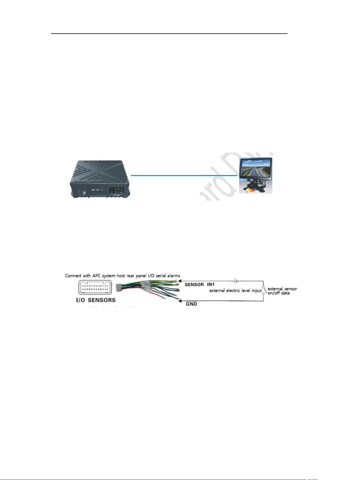
Setp7: Connect display output device
This product supports one channel video output, customers can choose the
display device according to the actual situation. Connect the AV OUT to the other
other of the display.
Alarm input wiring:
Connect the external sensor that needs to set the alarm to the 8 SENOR-IN
ports corresponding to the I/O SENSOR on the rear panel of the counter. The
external alarm input must be connected to the corresponding sensor switch
device (such as the door magnetic power supply, emergency switch button, turn
signal switch, brake lights, etc.), and then connected to the counter device
through the matching 24pin I / O interface cable.
For example:
The sensor in1 picks up the front door, and the counter obtains the front door
opening and closing signal;
The sensor in2 picks up the back door, and the counter obtains the back door
opening and closing signal.
Setp8: RS232/RS485 device access
This product provides 2*RS232 serial port and 1*RS485 input. Users can select
the required sensor, OBD, RS232 serial port or RS485 communication device
according to practical needs. When installing, first connect the external device
power cable and communication cable to the 24pin I/O port cable, and then
connect the 24PIN I/O port to the rear panel of the counter device. Finally, install
the probe of the external device and make reasonable wiring.
14/67
VM-6104-1080P MDVR User Manual
4.2.1 MDVR Assistant: MDVR Assistant is a mobile phone app that
interacts with mobile phones and devices. It transplants the terminal
settings of the device to the mobile phone to operate, simplify the
construction process and speed up the project progress.
Step9: Binocular camera wiring
Video line connection
There are two sets of camera video input and output, two video input interfaces,
respectively, according to the requirements of the first and second channels, the
new camera 3rd and 4th channel to reserve.
4. USB Tools & MDVR APP User-Guidance
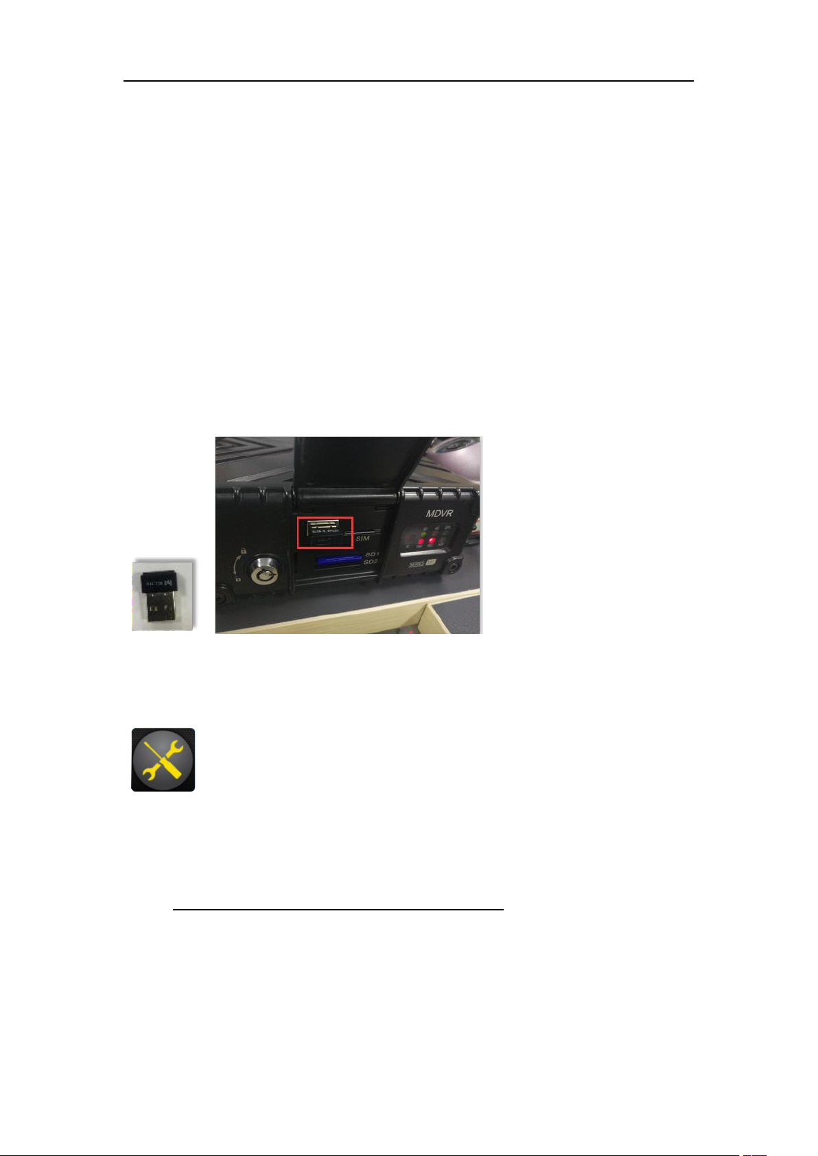
4.1 USB Tools:
The USB Tool is to insert in the front USB interface on the mdvr, like the
following picture.
4.2 MDVR Assistant
4.2.2 App Download: IOS system download it from APP STORE, named “MDVR
Assistant”.
Android system download from Web
Client: http://120.24.89.199:8088/808gps/login.html
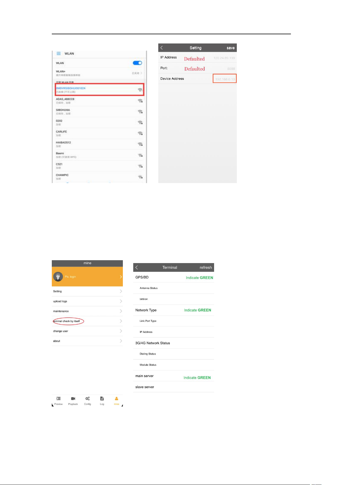
4.2.3 APP Connection:
15/67
VM-6104-1080P MDVR User Manual
1. connect your phone WIFI to the WIFI named "OMDVRSIBOHUI....", Password:
88888888;
log in the mobile app, in “MINE--->Setting”, change the “Device Address” to
192.168.0.10 --->“Save”
(The Defaulted setting of the “Device Address” is 192.168.0.10 it’s better not to
change)
4.2.4 Device Online “check by itself”:
Terminal check by itself: Here to check whether all connection is OK.
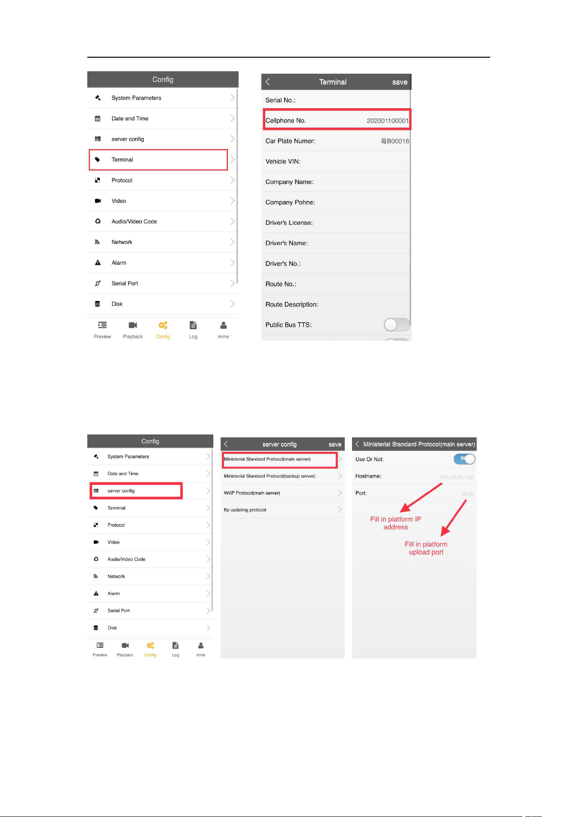
4.2.5 Terminal Setting:
16/67
VM-6104-1080P MDVR User Manual
In “Config”--->”Terminal”--->”Cellphone No” set a cellphone num, it should be the
same as the Device Num and Sim card Num when you add vehicles in platform.
(Usually the “Cellphone No” has been settled before delivery, it’s better not to
change)
4.2.6 Server Setting:
In “Config”--->”Server Config”--->”Ministerial Standard Protocol(main
server)--->”main server” do the setting as above. (Usually the setting has been
settled before delivery, it’s better not to change)
17/67
VM-6104-1080P MDVR User Manual
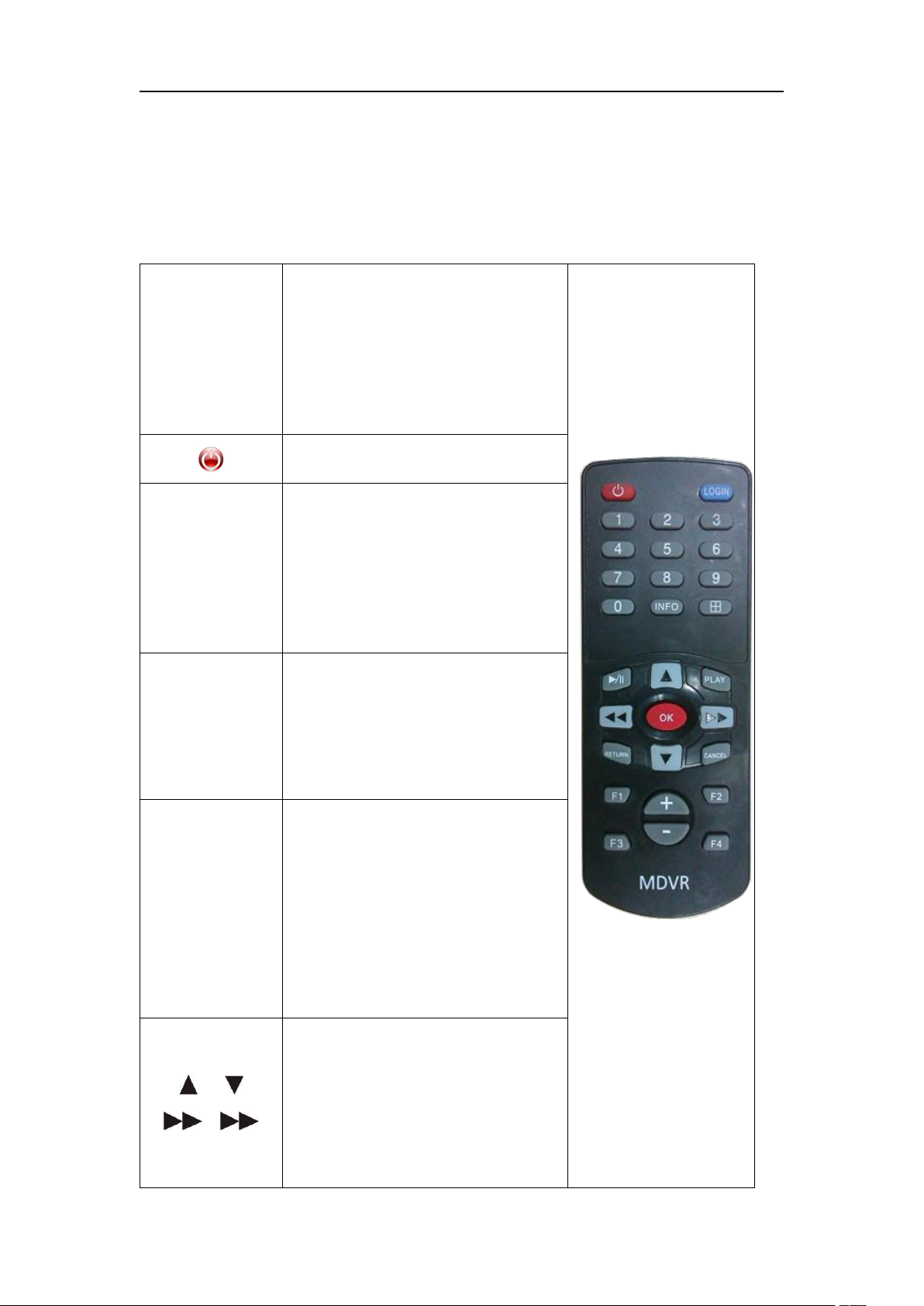
(LOGIN)
When the recorder has a
password, press the LOGIN
button to enter the password.
Since the system does not have
recovery and reset functions,
please remember the password.。
Power Button
0-9
Switch single screen display, set
the interface, press the number
keys to enter directly
0 and 9 keys take into account the
volume, brightness and other
functions to quickly set the
entrance
INFO
Through the shortcut key
operation under the direct
screen, you can view the module
status, alarm status, version
number and recording disk
status.
田
Power on default 4 screens,
under the monitor screen, for
switching between four screens
and eight screens, single screen;
press the field key to display 8
screens; press the number keys 1,
2, 3, 4, 5, 6, 7, 8 switch to single
screen CH1, CH2, CH3, CH4, CH5,
CH6, CH7, CH8 respectively
Up, down, left, and right arrow
keys
Left and right direction keys have
playback video fast forward and
rewind function has four files: 2X,
4X, 8X, 16X; boot display default
4 screen, press the up and down
5.MDVR Operation Guidance
5.1 Remote Controller Function Buttons Descriptions
18/67

VM-6104-1080P MDVR User Manual
buttons to switch between 1-4,
5-8 screens,
【OK】
Confirm
/‖
Pause playback and single-step
playback buttons when playing
back image data, each press can
play one step, press the playback
button to return to the normal
playback speed;
PLAY
Start the play button (the still
picture is displayed when the
screen is paused);
(RETURN)
Go back to the previous submenu.
Finally exit the setup menu and
exit to the monitor screen;
CANCEL
Delete/Return
+ —
Edit box to enter backspace, enter
key; volume adjustment button
F1、F2、F3、
F4
Alternate key
5.2 The user login
19/67

VM-6104-1080P MDVR User Manual
Press the login key to pop up the login menu. The Serial Num will be
displayed by default. The username will be distinguished by the password
entered
Distinguish user identity with password, there is administrator and common
user, administrative identity has all authority, common user has limited
authority, only read can not change.
The password switch is off, press the login key to enter the setting menu
directly, and the login interface will not pop up.
5.3 System operation and setup
instructions:
All the Settings of the following sub menus will take effect after confirming
[save], otherwise the Settings are invalid.
Enter the menu interface (including video query menu), and the device stops
recording
Input digital Num by pressing on the remote number keys directly or use a
soft keyboard. Input characters, letters by using soft keyboard.
Main menu: displays all main Settings: General settings, application setting,
20/67
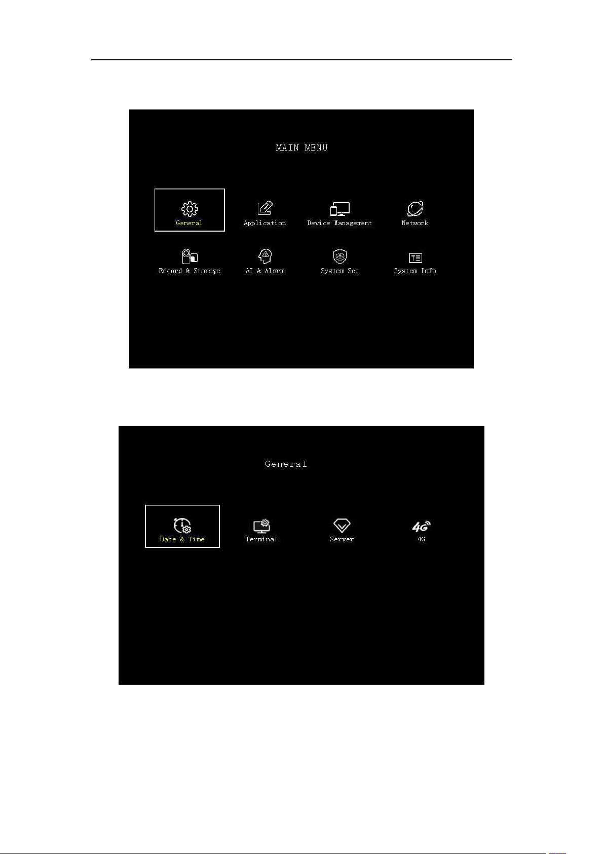
VM-6104-1080P MDVR User Manual
device management, network management, record and storage, AI and alarm,
system setting, system information.
5.3.1 General Settings: including date & time setting, terminal management,
server setting and 4G setting.
Time setting: you can set the time manually and set different time mode.
21/67
 Loading...