

Page 1
Vision Cover Lifter
CAN Patent No. 2,432,833
Patent Pending Made in Canada
US Patent No. 7290297B2
Top Mount ONLY
Assembly, Installation Instructions & Parts List
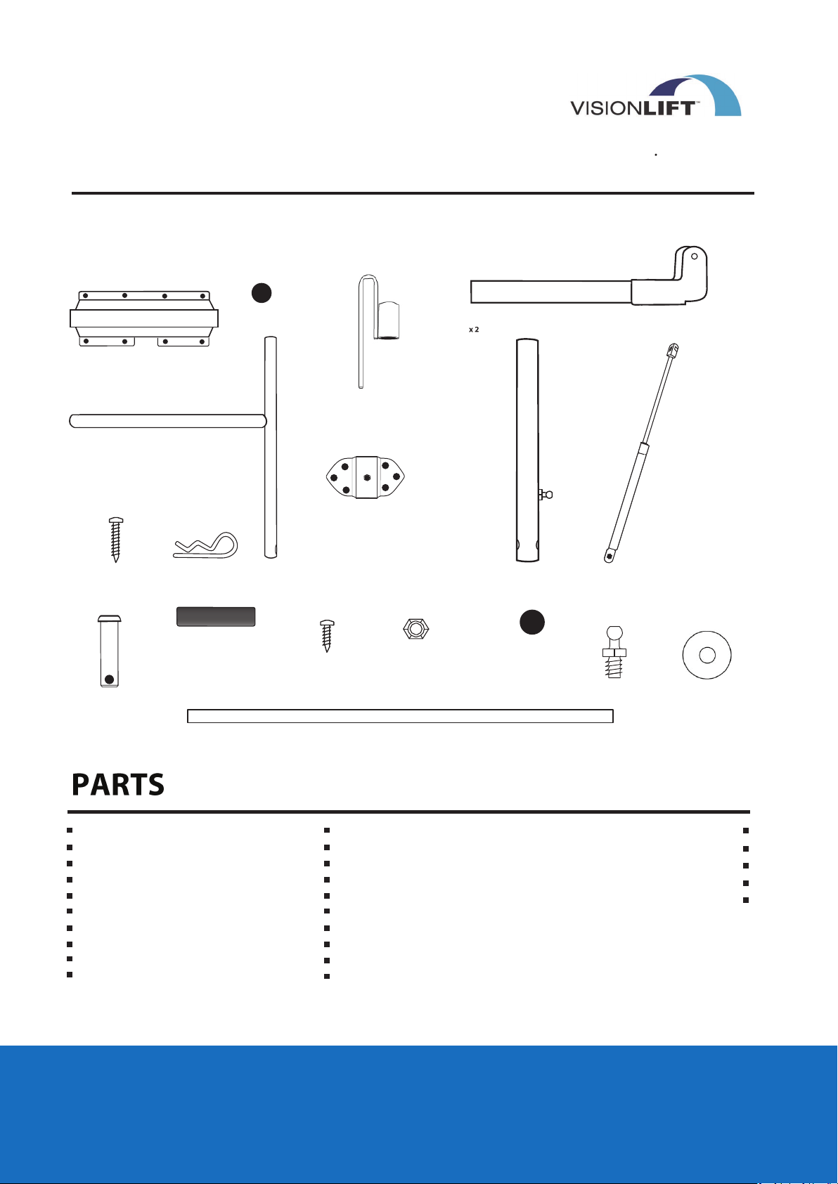
PARTS LIST
SMP Specialty Metal Products Inc. 326
Watline Avenue Mississauga, ON L4Z 1X2
1-800-597-1343
www.ultrapoolandspa.com
MOUNTING BRACKET ASSEMBLY
X 2
x x x x
SIDE SUPPORT ARM
X 2
#10 - 1" WOOD
SCREWS WITH CAPS
X 28
BOLT PIN x 2
CLEVIS PIN x 2
ROUND PLASTIC CAPS 1 1/8"
FOAM GRIP x 2
X 2
#10 - 5/8" SELF TAPPING
COVER HOOK X2
SCREWS WITH CAPS
X20
BALL STUD
BRACKET
X 2
SQUARE PLASTIC CAPS
5/16" NY-LOCK NUT
X 2
PIVOT ARM
with BALL STUD
X 2
ROUND PLASTIC CAPS 1 1/4"
SLIDER PIVOT BRACKET ASSEMBLY
X 2
X 2
STUD BOLT
X 2
HYDRAULIC ARM
X 2
NYLON WASHER X4
x x x
Side Support Arm (x2)
Mounting Bracket Assembly (x2)
Slider Pivot Bracket assembly (x2)
Hydraulic Arm (x2)
Ball Stud Bracket (x2)
Center Pole (x1)
Pivot Arm with Ball Stud (x2)
Cover Hooks (x2)
Round Plastic Caps 1 1/8" (x2)
Nylon Washers (x4)
ALPINE SPA POOL MODELS
CENTRE POLE
X 1
#10 - 5/8“ Self Tapping Screw (x20)
#10 - 1” Woodscrew (x28)
#10 Screw Caps (x42)
5/16” NY-Lock Nut (x2)
Foam Grip (x2)
Square Plastic Caps (x2)
Round Plastic Caps 1 1/4" (x2)
Stud Bolt (x2)
Bolt Pin (x2)
Clevis Pin (x2)
x x x
TOOLS LIST
Phillips screwdriver
Measuring tape
Drill
1/8 drill bit
Adjustable wrench
CUSTOM INSTRUCTIONS
Page 2
VISION COVER LIFTER
CAN Patent No. 2,432,833
Patent Pending Made in Canada
US Patent No. 7290297B2
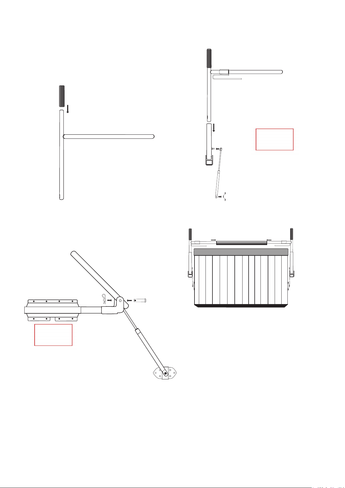
FOAM GRIP
FOAM GRIP ASSEMBLY
FOAM
COVER
GRIP
HOOK
ILLUSTRATION FOR ATTACHING
the HYDRAULIC ARM
SIDE SUPPORT ARM
MOUNTING BRACKET ASSEMBLY
AFTER YOU SOAK FOAM WITH
SOAPY WATER TWIST FOAM
DOWN ONTO HANDLE
PIVOT ARM
with BALL STUD
CLEVIS PIN
BOLT PIN
PIVOT ARM
with BALL
STUD
BALL STUD
BRACKET
PIVOT ARM
with BALL STUD
x
x
x
SLIDER PIVOT
BRACKET
HYDRAULIC
ARM
BALL STUD
BRACKET
FRONT VIEW - CENTRE POLE ASSEMBLY
COVER
HOOK
CENTRE POLE
SIDE SUPPORT ARM
XXXXX
SPA COVER
x: Self Tapping Screw
•: Wood Screw
COVER
HOOK
XXXXX
SIDE SUPPORT ARM
PIVOT ARM
with BALL
STUD
BALL STUD
BRACKET
X X X X
SLIDER PIVOT BRACKET
x: Self Tapping Screw
•: Wood Screw
HYDRAULIC ARM
SIDE VIEW - ILLUSTRATION FOR ASSEMBLY OF
MOUNTING BRACKET SLIDER PIVOT BRACKET AND
PIVOT ARM WITH BALL STUD
BALL STUD
BRACKET
Allow the Ultralift to rest on the spa cover. The
center pole is located 1 inch from the middle seam
of the spa cover on the lifter side. Attach the
center pole to the side support arms using six of
the #10 - 5/8” self tapping screws. Pre-drilling
through the side support arms is advised. We
recommend rotating the center pole so that the
screws are inserted horizontally.
Page 3
VISION COVER LIFTER
CAN Patent No. 2,432,833
Patent Pending Made in Canada
US Patent No. 7290297B2
X X X X
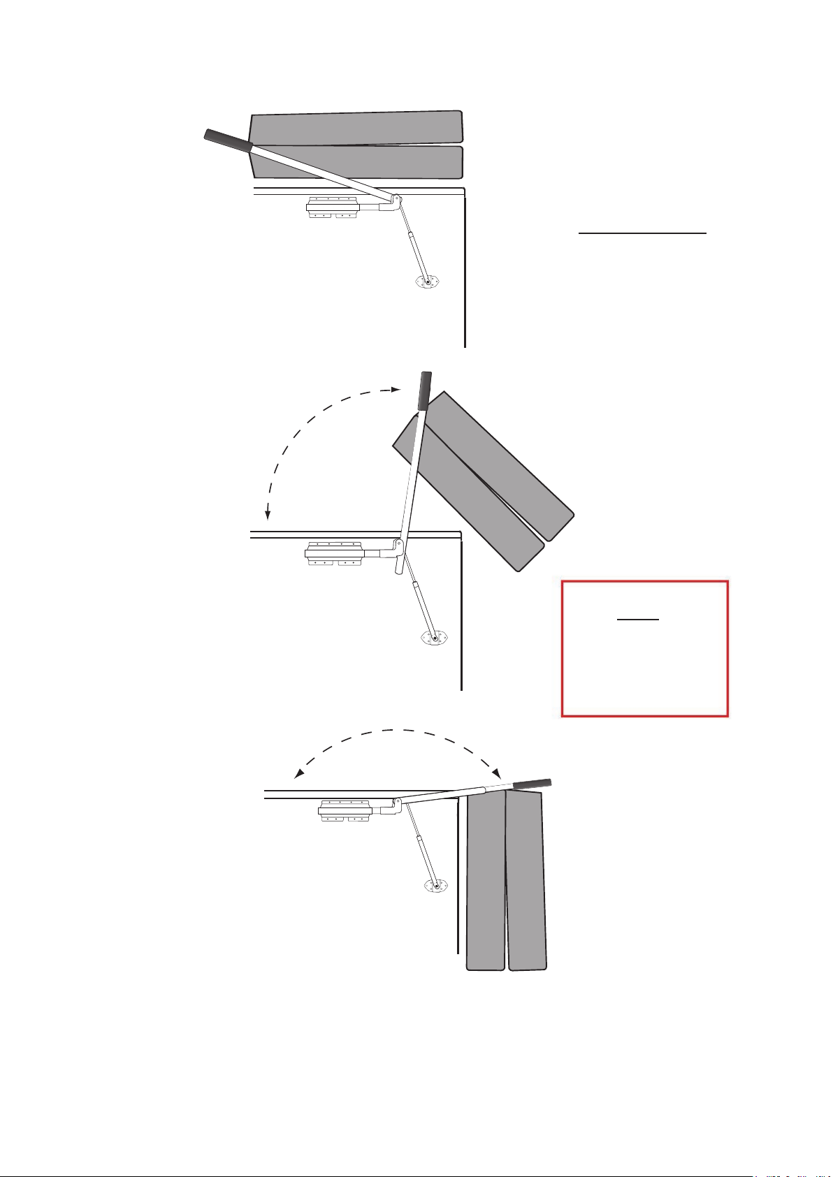
CAUTION:
DO NOT USE
the VisionLift in windy conditions.
The spa cover may blow over and
impact the spa user.
X X X X
X X X X
TIP
If you purchase your tub with a
Composite Cabinet, (rather than
wood) reinforcing the inside of
your cabinet when screwing the
rear ball stud bracket into it will
strengthen the attachment.
Page 4
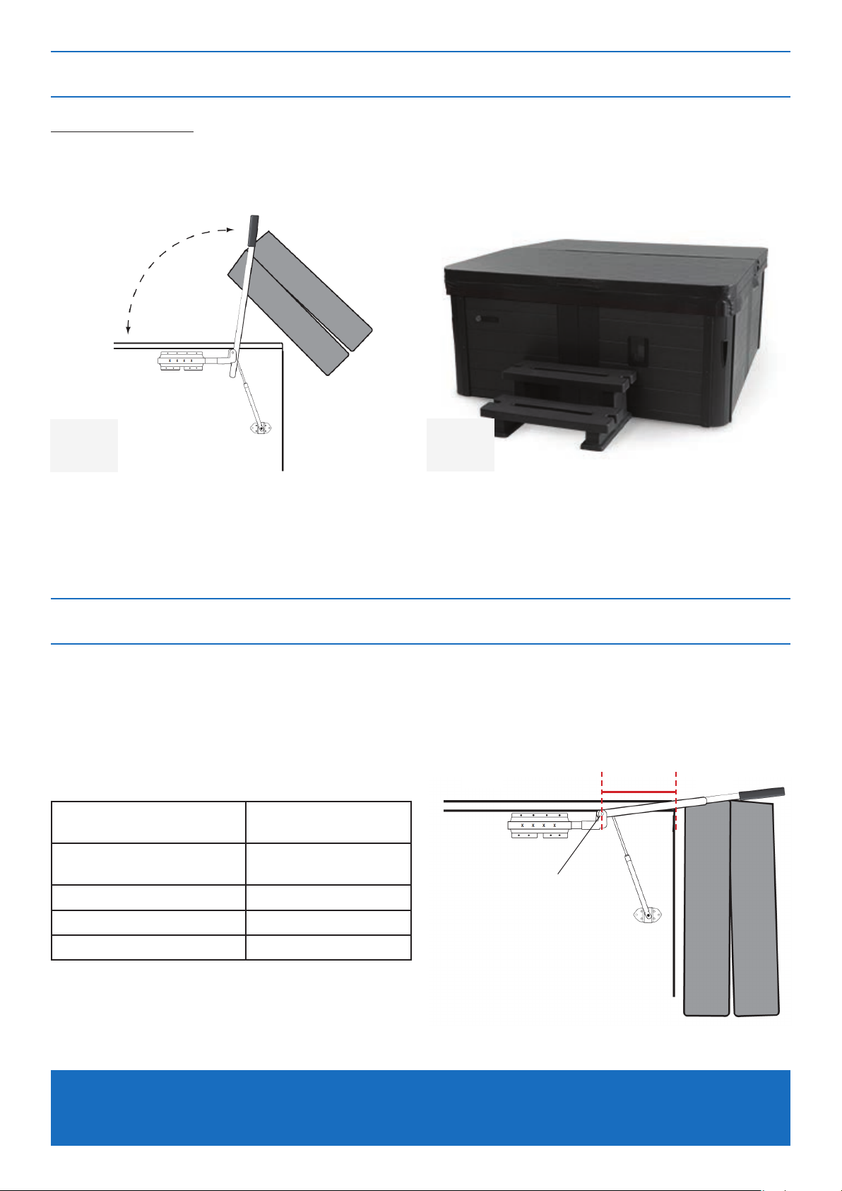
STEP 1 - POSITION THE SPA COVER
Parts Required:
- Spa Pool Cover
1
Determine which side of the spa you want to
install the Vision Lift on. The cover will fold as
per the diagram above.
2
Position the spa cover in the closed position
on the spa in your desired orientation.
Make sure that the four corners are evenly
positioned and it’s sitting square.
STEP 2 - DETERMINE THE MOUNTING BRACKET POSITION
Where the Mounting Brackets are installed on the cabinet is determined by the distance from
the back edge of the spa pool to the ‘pivot point’.
Use the table below to nd the pivot point distance (X) for your spa pool model:
X
Spa Model Pivot Point Distance
(X)
Nova, Aspen,
Whistler, Blackburn, Summit
Matterhorn 40cm
37cm
Pivot Point
Vancouver 42cm
Munro, K2 45cm
X = pivot point distance
TIP – This guide references specic Alpine Spa models. Non-Alpine Spa pools should
follow the original Vision Lift instructions.
Page 5
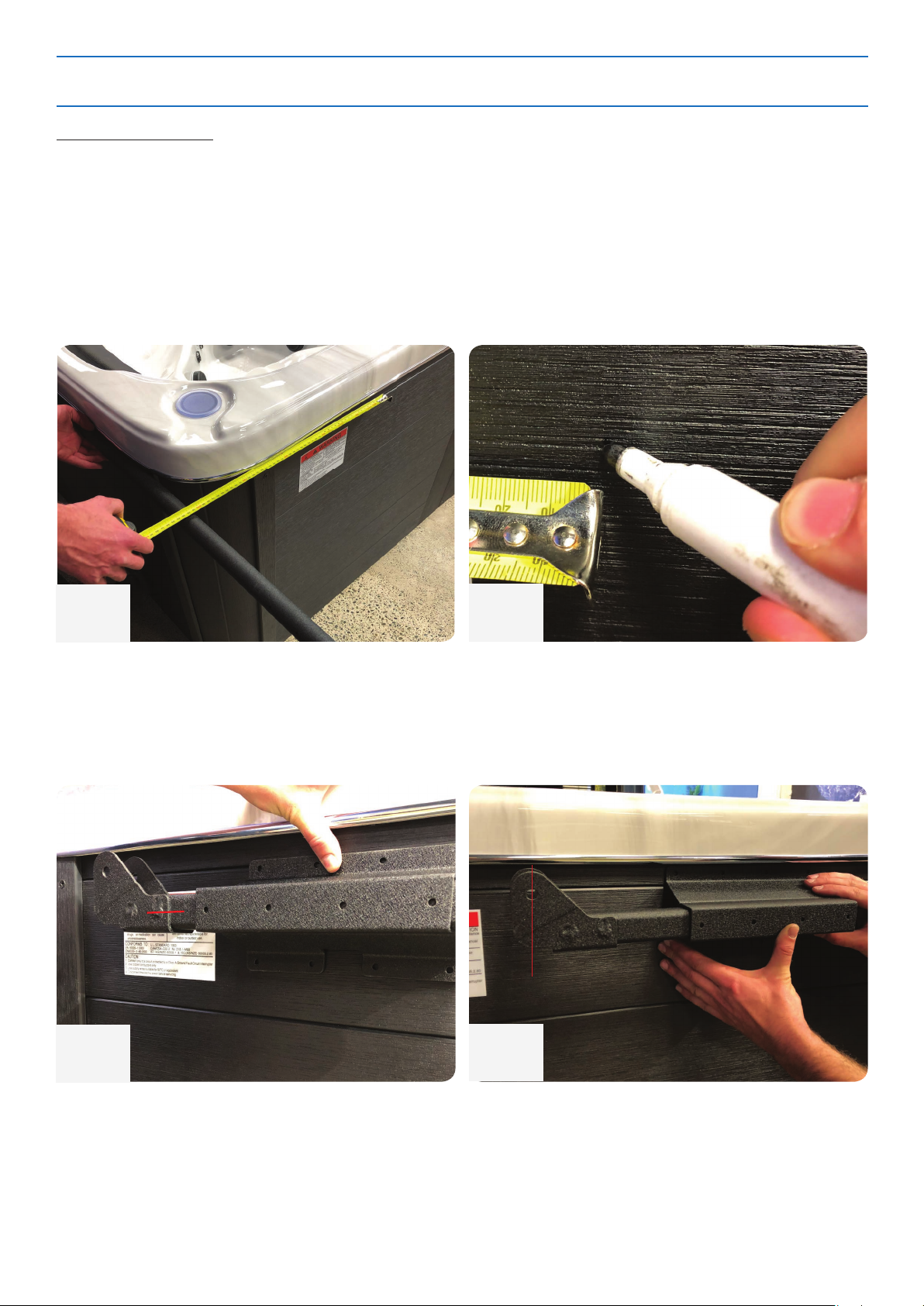
STEP 3 - INSTALLING THE MOUNTING BRACKETS
Parts Required:
- Measuring Tape
- Marker/Chalk
- Straight Edge (or use the ‘centre pole’ piece temporarily.)
- Drill & Drill Bits
- 1” Wood Screws
- 5/8” Self-Tapping Screws
1
Using the ‘Centre Pole’ part as a straight edge
on the back edge of the spa, measure forward
on to the cabinet your ‘pivot point distance (X)’
from the table on the previous page.
>
3
2
Clearly mark this position (measure twice,
install once). Repeat this step on the opposite
side of the spa pool.
4
Slide the ‘Slider Pivot Bracket’ into the
‘Mounting Bracket’, making sure the pivoting
point is facing upwards and the gap in the
‘Mounting Bracket’ is on the bottom as per
the above photo.
Fit the mounting bracket to sit ush under
the edge of the acrylic shell and position the
‘Slider Pivot Bracket’ so that the hole lines up
with the mark made in step #2.
Page 6
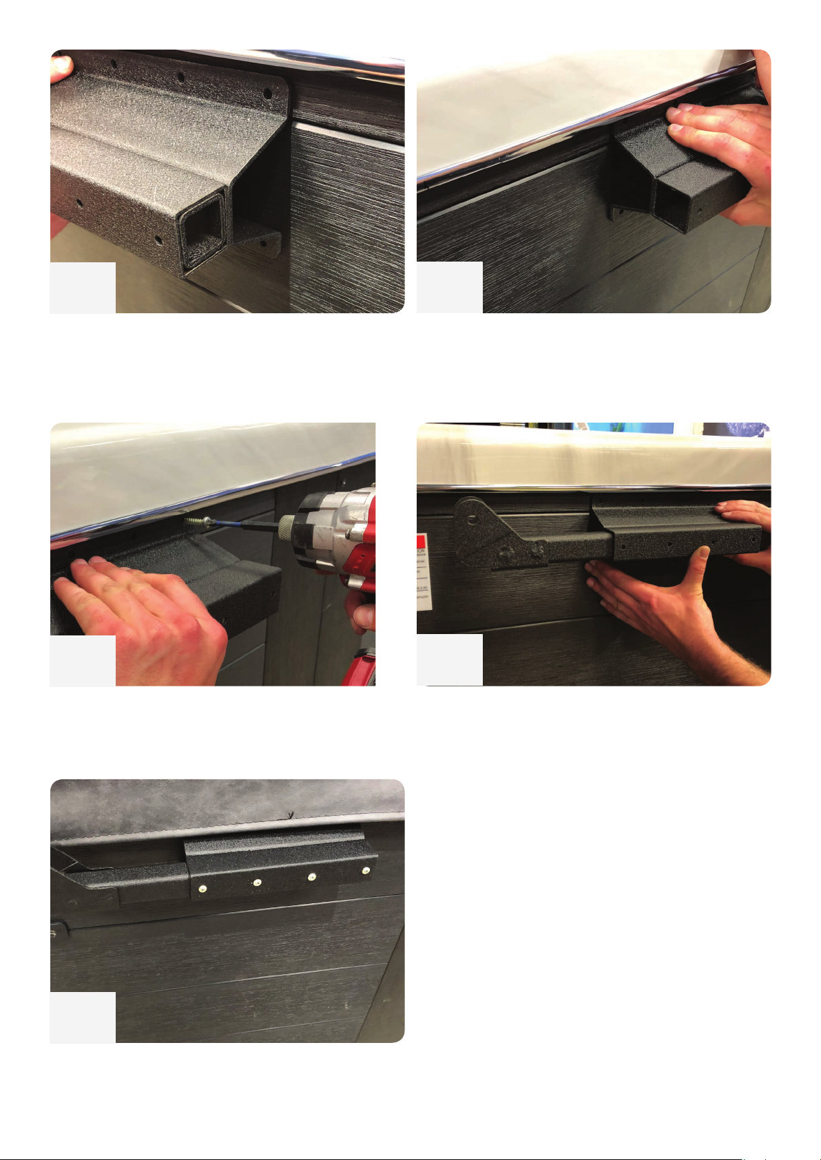
5
6
While holding the ‘Slider Pivot Bracket’ tightly
in place and in-line with your mark, adjust the
‘Mounting Bracket’ to be ush over the end of
the ‘Slider Pivot Bracket’.
7
Screw the ‘Mounting Bracket’ onto the spa
pool cabinet using the ‘1” WoodScrews’.
Repeat on opposite side of spa pool.
Hold the ‘Mounting Bracket’ tightly in place
and remove the ‘Slider Pivot Bracket’ from the
‘Mounting Bracket’.
8
Insert the ‘Slider Pivot Bracket’ back into the
secured ‘Mounting Bracket’ and line up the
‘Pivot Point’ hole with the original mark made.
9
Secure the ‘Slider Pivot Bracket’ to the
‘Mounting Bracket’ with the ‘5/8” Self-Tapping
Screws’.
Page 7
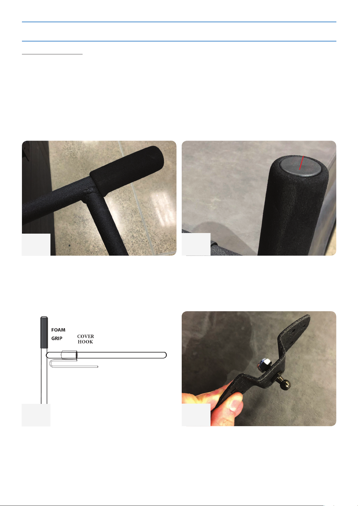
STEP 4 - PREPARING THE SIDE SUPPORT ARMS
Parts Required:
- Side Support Arms
- Foam Grips
- Round Plastic Caps 1 1/8”
- Ball Stud Brackets
- Stud Bolts
- 5/16” Ny-Lock Nuts
- 13mm Spanner / Socket Wrench
>
1
Install the ‘Foam Grips’ onto the ‘Side Support
Arms’. Lubricate the interior of the grips with a
dab of dish washing liquid to make it easier to
slide on.
3
2
Insert the ‘Round Plastic Caps 1 1/8”’ into the
end of the side support arm with the freshly
installed foam grip.
4
Slide the ‘Cover Hook’ over the ‘Side Support
Arm’ as shown in above diagram. Repeat for
both arms.
Insert the ‘Stud Bolt’ into the centre hole of
the ‘Ball Stud Bracket’ using the ‘5/16” NyLock Nut’ and tighten with a 13mm spanner
and/or socket. Repeat for both ‘Ball Stud
Brackets’.
Page 8
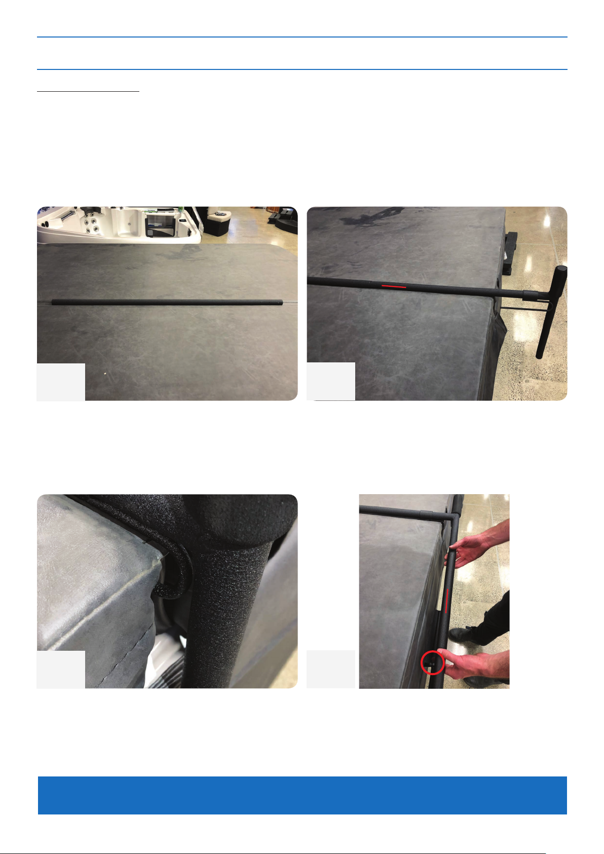
STEP 5 - ASSEMBLING THE SIDE SUPPORT ARMS
Parts Required:
- Side Support Arms with Cover Hooks
- Center Pole
- Pivot Arm with Ball Stud
- Bolt Pins
- Clevis Pins
- Nylon Washers
>
1
With the cover in the closed position on the
spa, place the ‘Centre Pole’ in the middle of
the cover along the seam.
3
2
Slide the longer side of each ‘Side Support
Arm’ into both ends of the ‘Centre Pole’.
>
4
Ensure the ‘Cover Hook’ slides between the
cover seam and the middle of the cover.
TIP – See page 2 for front view of support arm assembly diagram for reference.
Now slide the ‘Pivot Arm with Ball Stud’ over
the ‘Side Support Arm’ so that the ball stud
faces the side of the spa pool.
Page 9
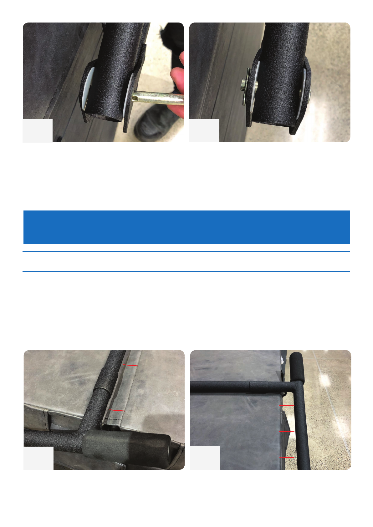
5
6
Attach the ‘Pivot Arm with Ball Stud’ to the
‘Pivot Arm’ using 2x ‘Nylon Washers’ and
the ‘Bolt Pin’. Place a washer each side of
the holes at the bottom of the ‘Pivot Arm’.
Align these with the holes in the ‘Slider Pivot
Bracket’ and slide the ‘Bolt Pin’ through.
TIP – This bit can be a little tricky, but persistence is key! Have your Bolt Pin and Clevis
Pin close by.
STEP 6 - SECURING THE ARMS & BALL STUD BRACKET
Parts Required:
- Side Support Arms with Cover Hooks
- Center Pole
5/8” Self-tapping Screws
-
- Ball Stud Brackets
- Hydraulic Arms
Insert the ‘Clevis Pin’ through the ‘Bolt Pin’ to
hold it in place. Repeat this on both sides.
>
>
1
Adjust the assembly as necessary so that the
‘Centre Pole’ is just aligned with the lifter side
centre seam of the cover as per photo above.
>
>
2
Adjust the assembly on each side as
necessary so that the ‘Side Support Arms’ are
square and in line with the ‘Pivot Arms’.
>
Page 10
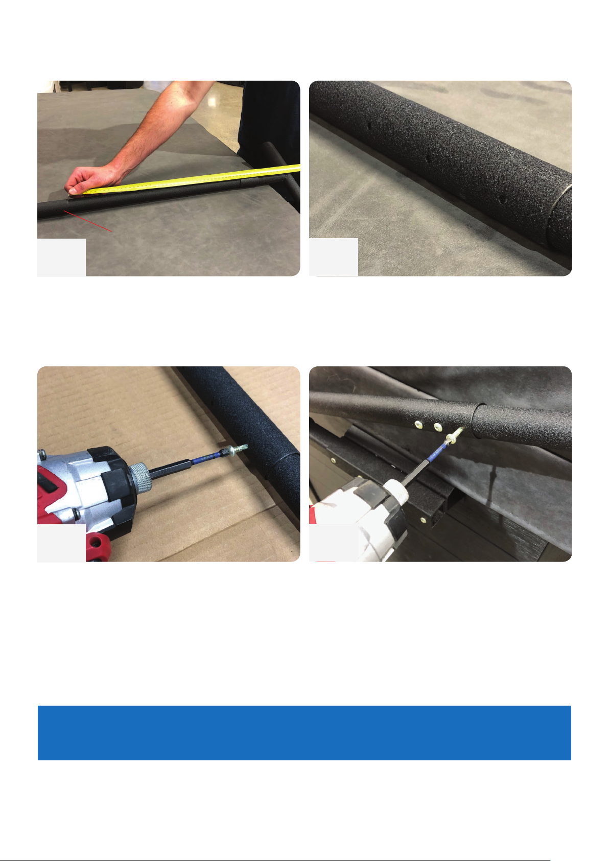
Center Pole
3
Adjust the assembly as necessary so that the
‘Centre Pole’ is centered evenly in the middle
of the cover.
5
4
Twist and rotate the ‘Center Pole’ so the
screw holes are facing the back of the spa
pool (the way the cover will be lifting off).
6
Place a protective layer of cardboard between
the cover and the ‘Centre Pole’, then proceed
to secure the ‘Centre Pole’ to the ‘Side
Support Arms’ using the ‘5/8” Self-tapping
Screws’.
TIP – Always check the ‘Centre Pole’ is in place and the ‘Pivot Arms’ are square to the
spa pool before installing the self-tapping screws.
Secure the ‘Pivot Arms’ to the ‘Side Support
Arms’ using the same self-tapping screws.
Page 11
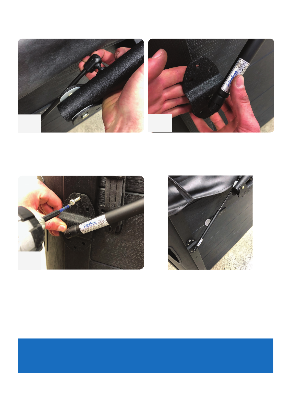
7
8
Clip the top of the ‘Hydraulic Arm’ onto the
ball stud located on the ‘Pivot Arm’.
Attach the other end of the ‘Hydraulic Arm’
onto the ‘Ball Stud Bracket’ prepared in step
#4.
9
Adjust the ‘Hydraulic Arm’ so the ‘Ball Stud Bracket’ sits over the cabinetry slat. Secure this
with the 1” Woodscrews.
TIP – If your spa pool doesn’t have a vertical slat, mount the ‘Ball Stud Bracket’ at the
edge of the radius of the spa corner. If the Ball Stud Bracket covers one of the cabinetry
screws in the slat, use the screw from the slat.
Page 12
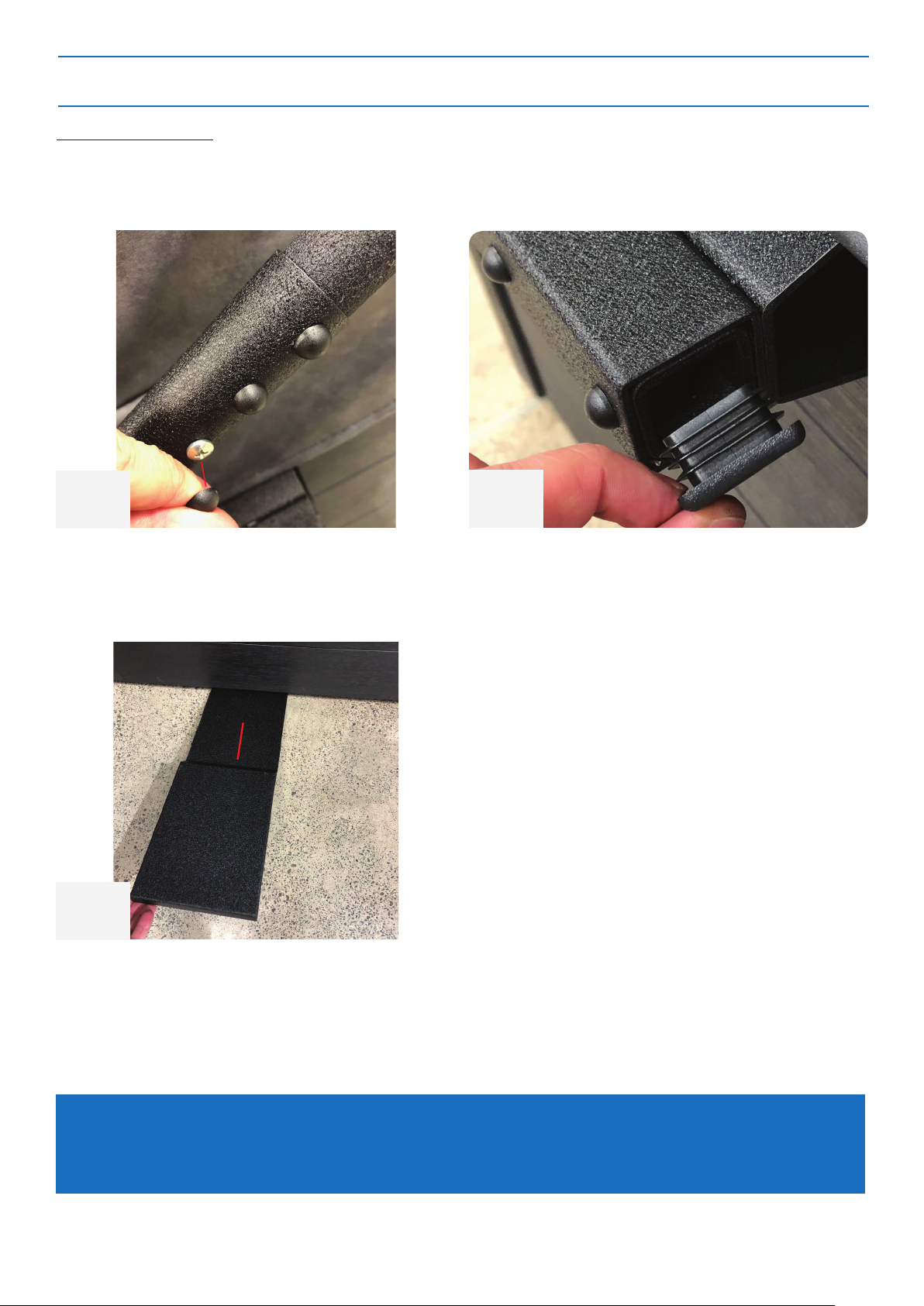
STEP 7 - FINISHING TOUCHES & USE
Parts Required:
- Plastic screw caps
- Square plastic caps
>
1
Fit all the visible screws with ‘Plastic Screw
Caps’.
>
3
2
Fit the ‘Square Plastic Caps’ into the pivot
bracket assemblies. Th
Slide the protecting ‘Floor Pads’ under the
spa pool base on the side which the cover will
be lifting off. This will protect the cover from
sitting directly on the ground.
TIP – The ‘Floor Pads’ will need to be installed when the spa pool is empty. Two
persons can lift the spa pool gently via holding under the acrylic shell while sliding the
pads under the base.
Page 13

To make a
ship any said parts back to the manufacturer. The warranty includes all Labor costs performed at the manufacturer's facility
but not labor in the field. SMP will cover the cost(s) to repair and/or replacement of the items back to the retailer or seller.
Consequential Damages:
consequential damages, so the above mentioned limitation may not apply to you).
It is important that you report to the Retailer from whom you purchased UltraLift, any defects as soon as they are
A
venue, Mississauga, Ontario Canada, L4Z 1X2; Phone: 1-800-597-1343, Email: [email protected]
THE WARRANTY:
SMP Specialty Metal Products Inc. warrants to you (the original purchaser) for the stated warranty term of FIVE YEARS
(60 Months) from the original date of purchase, to be free from defects in material and workmanship.
UltraLift Cover Lifters will be free from defects in materials or workmanship that would cause the lifter to be inoperable in
normal working conditions. Any claim made within these terms for Five years from the date of purchase will be repaired or
replaced at the option of the Manufacturer.
This is a 100% Non-Prorated Warranty on all parts for the full 5 years. Only parts excluded from the warranty are the gas
springs which include a 100% One Year Warranty.
EXCLUSIONS TO WARRANTY
Lifter has been subjected to alteration, misuse or repairs by anyone other than an authorized representative
of the Manufacturer, unless written approval is provided
Damage caused by improper installation or during transportation from the seller to the purchaser
Any damage resulting from any misuse, abuse, negligence, accident or alteration, environmental, or use during
high winds
The warranty covers the operational use of the lifter but does not cover scratches, abrasions, rusting or any defects to the
finish of the material caused by or resulting from the exposure to the environmental factors; i.e. sun, rain, chemicals or any
defects resulting from normal fading or minor deterioration.
The warranty does not cover damage resulting from abuse or accidents, including but not limited to the following damage:
Use of abrasive or unapproved cleaners that could cause surface damage
Subjection to solvents or other chemicals which could deteriorate painted surfaces
Use for any other purpose than as a Spa or Hot tub cover lifter
FREIGHT DAMAGE:
Any materials damaged in freight will be replaced by SMP Specialty Metal Products provided the purchaser files the
appropriate claims form with the carrier, and submits copies to the manufacturer within five (5) business days of receiving
the damaged merchandise. All claims should also be reported to the seller.
by SMP Specialty Metal Products Inc.
CAN Patent No. 2,432,833
Patent Pending Made in Canada
US Patent No. 7290297B2
MAKING A CLAIM:
warranty claim; in the event of a defect covered by this warranty for UltraLift, contact the original retail seller and
provide original purchase receipt, any photo(s) clearly showing the defect(s) and an explanation. NO RETURNS OF
MERCHANDISE WILL BE ACCEPTED UNTIL A "RETURN AUTHORIZATION NUMBER" HAS BEEN ISSUED.
The lifter will be repaired or replaced at the discretion of the Manufacturer. If necessary, the purchaser is responsible to
SMP Specialty Metal Products Inc. will not be liable for any loss, expense, or damage other than to UltraLift, that may result
from a defect in materials or workmanship. This warranty does not cover incidental damages including damage to property or
injury arising from the use or inability to use this product. Manufacturer or Seller shall in no event be liable for any amount in
excess of the original purchased amount. (Some Provinces / States do not allow the exclusion or limitation of incidental or
detected. If it is impractical to report any defects to the Retailer, Contact
SMP Specialty Metal Products Inc. 326 Watline
 Loading...