

Page 1
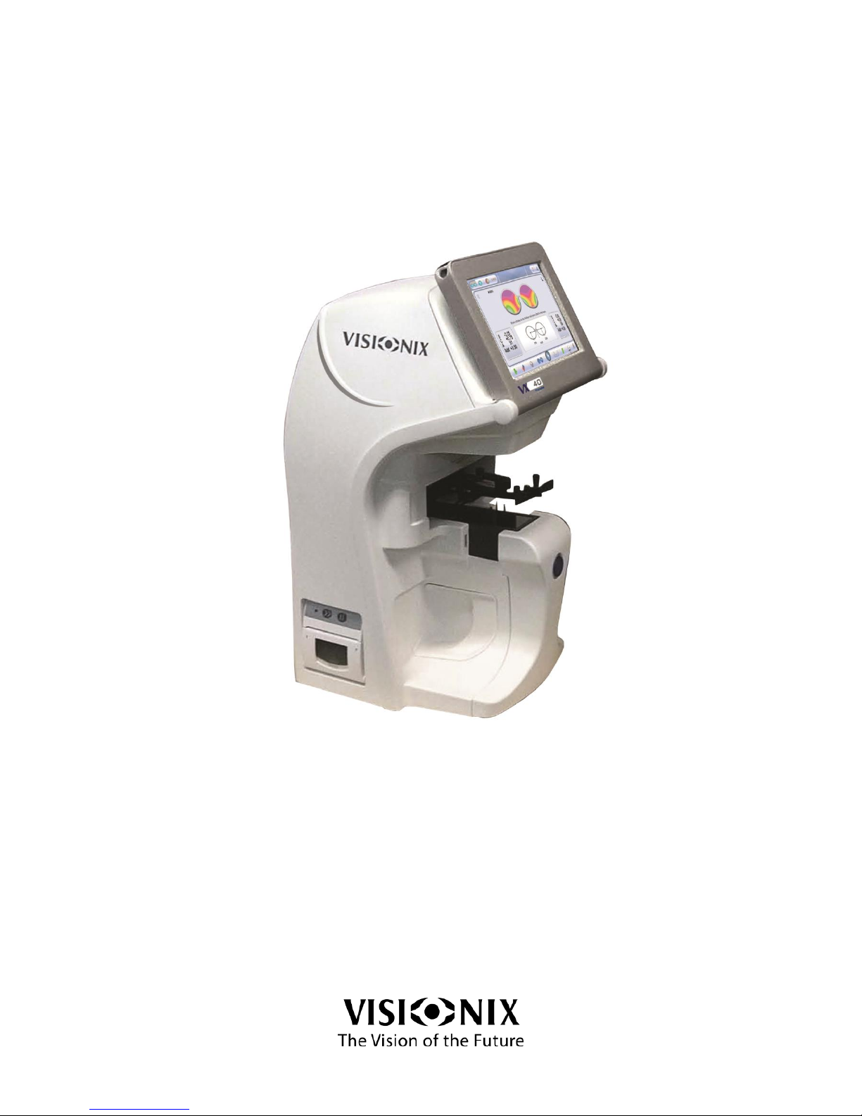
VX40
User Guide
UM30141000-ENG/v08_EN/2014-01-19/v2.0
Page 2

Page 3

VX40 User Guide
3 / 53
C
C
C
o
o
o
n
n
n
t
t
t
e
e
e
n
n
n
t
t
t
s
s
s
1. Introduction....................................................................................................... 6
1.1 Overview ........................................................................................................... 7
1.2 Scope ................................................................................................................ 7
2. Safety ............................................................................................................... 8
2.1 General.............................................................................................................. 9
2.2 Electricity ........................................................................................................... 9
2.3 Transport, storage and handling ....................................................................... 9
2.4 Precautions during use ..................................................................................... 10
2.5 Symbols ............................................................................................................ 10
3. Equipment and Installation .............................................................................. 11
3.1 List of Equipment Supplied ............................................................................... 12
3.2 Equipment Parts ............................................................................................... 12
VX40 Front View ................................................................................................... 12
VX40 Rear View .................................................................................................... 13
VX40 Side View .................................................................................................... 14
3.3 Installation Procedures ..................................................................................... 14
Site Requirements................................................................................................. 14
Opening the Box ................................................................................................... 14
Electrical connection ............................................................................................. 16
3.4 Starting and shutting down the device ............................................................. 16
Starting .................................................................................................................. 16
Shut Down ............................................................................................................. 16
4. Using the VX40 ................................................................................................ 17
4.1 General.............................................................................................................. 18
4.2 Frame Interface ................................................................................................. 18
Pupil Distance Measurements .............................................................................. 20
Prism Caluclation .................................................................................................. 20
Prism Calcluation Results ..................................................................................... 21
4.3 Analyze Interface .............................................................................................. 22
4.4 Lens Interface ................................................................................................... 23
4.5 Compare Interface ............................................................................................ 24
5. Configuring the VX40 ....................................................................................... 25
5.1 Configuration Access ........................................................................................ 26
5.2 User Settings ..................................................................................................... 26
5.3 Advanced Settings ............................................................................................ 27
5.4 Technical Settings ............................................................................................. 28
6. How to? ............................................................................................................ 29
6.1 How do I measure a frame? ............................................................................. 30
Go to frame interface ............................................................................................ 30
Place the frame ..................................................................................................... 30
Select the option of measurement ........................................................................ 31
Start the measurement ......................................................................................... 31
Abort the measurement ........................................................................................ 31
Extract the frame ................................................................................................... 31
6.2 How do I measure a lens (without frame)? ...................................................... 32
Select lens interface .............................................................................................. 32
Page 4

VX40 User Guide
4 / 53
Place the lens ........................................................................................................ 32
Start the measurement ......................................................................................... 32
Abort the measurement ........................................................................................ 32
Release the lens ................................................................................................... 32
6.3 How do I change the cylinder convention? ...................................................... 33
In the settings screen ............................................................................................ 33
On the main screens ............................................................................................. 33
6.4 How do I change the map type? ....................................................................... 33
6.5 How do I change lens type? ............................................................................. 33
6.6 How do I clear data? ......................................................................................... 34
In compare interface ............................................................................................. 34
In other interfaces ................................................................................................. 34
6.7 How do I analyze a lens? .................................................................................. 34
Go to analyze interface ......................................................................................... 34
See local values .................................................................................................... 34
6.8 How do I print out results? ................................................................................ 35
6.9 How do I send data? ......................................................................................... 36
Preparation ............................................................................................................ 36
Connection ............................................................................................................ 36
Settings ................................................................................................................. 36
Send the data ........................................................................................................ 36
6.10 How do I export data? ................................................................................... 37
Connection ............................................................................................................ 37
Settings ................................................................................................................. 37
Send the data ........................................................................................................ 38
6.11 How do I compare lenses? ........................................................................... 38
Save the data ........................................................................................................ 38
Go to analyze interface ......................................................................................... 38
6.12 How do I upgrade the software? ................................................................... 38
6.13 How do I refresh the system? ....................................................................... 38
6.14 How do I pack the system? ........................................................................... 40
7. What should I do if … ? ................................................................................... 41
7.1 There is a warning message ............................................................................ 42
7.2 The technician needs remote diagnostics ........................................................ 43
7.3 The system stops, or if malfunctions are observed .......................................... 44
7.4 The nose of the frame holder is blocked .......................................................... 44
7.5 I got a wrong measurement on trial lenses ...................................................... 44
7.6 I get wrong measurements ............................................................................... 44
8. Maintenance ..................................................................................................... 45
8.1 General.............................................................................................................. 46
8.2 Cleaning ............................................................................................................ 46
8.3 Printer paper replacement ................................................................................ 46
8.4 Fuse Replacement ............................................................................................ 47
8.5 Cap Replacement ............................................................................................. 47
Holder Caps Replacement .................................................................................... 48
Blocker Caps Replacement .................................................................................. 48
Detector Caps Replacement ................................................................................. 49
Base Caps Replacement ...................................................................................... 49
9. Appendices....................................................................................................... 50
9.1 Specifications .................................................................................................... 51
9.2 Conformity with International Standards .......................................................... 51
Page 5

VX40 User Guide
5 / 53
Directives and standards ...................................................................................... 51
Manufacturer ......................................................................................................... 51
Waste Electrical and Electronic Equipment (WEEE) Directive ............................ 52
9.3 Glossary of Terms ............................................................................................. 52
9.4 Contact information ........................................................................................... 53
Page 6

Introduction
VX40 User Guide
6 / 53
1. Introduction
Page 7

Introduction
VX40 User Guide
7 / 53
1.1 Overview
The VX40 is an Automatic Lensmeter which provides a very accurate measure of
the refractive power of lenses and displays the spherical aberration, the cylindrical
properties and the axis of the lenses.
The Automatic Lensmeter also contains the P.D. (pupillary distance) measurement.
It can measure both uncut single lenses and framed glasses. Furthermore, it
provides automatic detection of multi-focal lenses.
This advanced next generation lens meter comes with an intuitive user interface to
enable the user to perform lens measurements simply and easily.
1.2 Scope
This manual contains information for the proper use, storage and maintenance of
the VX40, as well as important safety information.
For best results, before using the device, review this manual in its entirety and
become familiar with its contents.
Warning
This document contains confidential information that is the property of Luneau SAS.
Any use, reproduction or transmission of this material, in part or in whole, is strictly
forbidden. This document is provided for the exclusive use of Luneau SAS
employees and other authorized users.
The content of this User Guide may be modified without warning. The images are
not contractual. Every reasonable effort has been made to ensure that its content is
accurate. For further information please contact a Luneau SAS representative.
Copyright ©2012 Luneau SAS. All rights reserved.
Page 8

Safety
VX40 User Guide
8 / 53
2. Safety
Page 9
Safety
VX40 User Guide
9 / 53
2.1 General
Luneau SAS provides sufficient information to ensure patient safety, avoid system
malfunctions, and prevent incorrect readings.
Luneau SAS is not responsible for injury to patients or damage to equipment
resulting from ignorance of or failure to follow its safety instructions.
The safety information appears in the form of warnings and alert messages.
Important!
Never attempt to disassemble or reassemble the equipment.
Do not modify the equipment in any way.
Repairs and maintenance must be carried out only by qualified service
personnel.
2.2 Electricity
Important!
To avoid risk of electric shock or bodily injury, do not handle the electrical plugs
with wet hands.
To avoid risk of electric shock or fire, make sure the VX40's power cord is not
damaged before plugging it into an electrical outlet.
To avoid risk of electric shock, the power cord should be fully inserted in an outlet
equipped with a protective ground connection.
2.3 Transport, storage and handling
Important!
Before packing, follow 6.14. How do I pack the system? Page 40.
Transport the VX40 in its original packaging.
Check the good condition of the packaging.
Do not subject the VX40 to strong vibrations. Shocks or violent movements can
cause malfunctions.
Page 10
Safety
VX40 User Guide
10 / 53
2.4 Precautions during use
Important!
Do not place or use the VX40 in direct sunlight.
Do not expose the VX40 to excessive dust or humidity.
Do not place the VX40 in a hot air current (e.g. above a heater).
Do not obstruct the ventilation vents.
Never place the VX40 close to the following types of equipment which can
interfere with the reception of commands from the remote control:
halogen lamp (direct or indirect),
flu compact lamp,
equipment emitting infrared radiation (e.g. autophoroptor, automatic
tonometer, etc.).
Keep the screen surface clean. Protect it from dust, fingerprints and shocks.
When you switch off the VX40, wait at least 5 seconds before switching it on
again.
2.5 Symbols
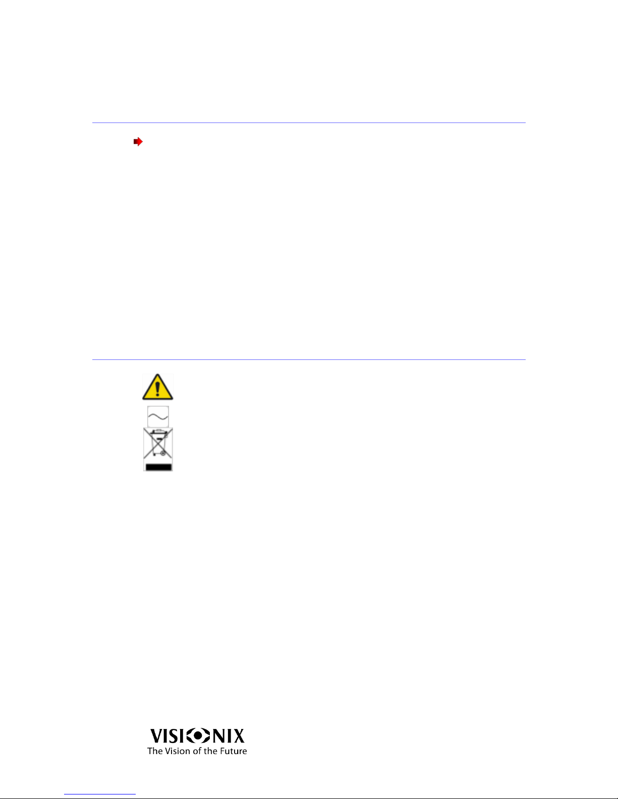
Important: consult the documents supplied with the equipment
Alternating current
The equipment must be returned to the manufacturer for scrapping
Page 11

Equipment and Installation
VX40 User Guide
11 / 53
3. Equipment and Installation
Page 12
Equipment and Installation
VX40 User Guide
12 / 53
3.1 List of Equipment Supplied
The VX40 is supplied with a securing plastic cover and a set of accessories as listed
below:
Touch screen stylus pen
Power cable
2x paper rolls in the box and 1x roll already installed
2x 2A fuses
Test frame (T30148012)
4x rubber caps
3x detector pin caps
3x long spring loaded pin caps
Lens cleaning cloth
Dust cover
User manual
3.2 Equipment Parts
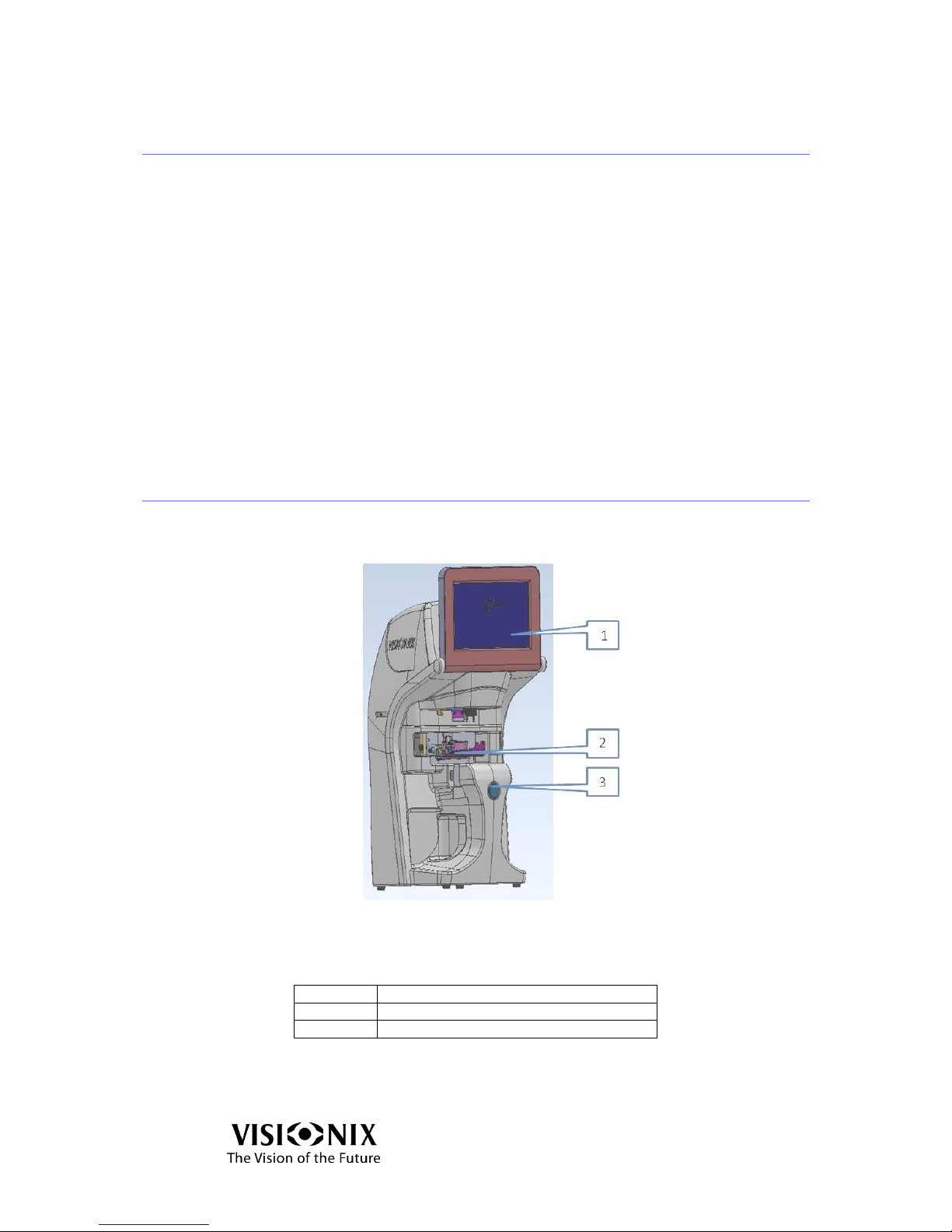
VX40 Front View
Figure 3-1: VX40 Front View
Table 3-1: VX40 Front View Components
1
LCD Touch Screen
2
Frame Holder
3
Measurement Start/Stop Button
Page 13
Equipment and Installation
VX40 User Guide
13 / 53
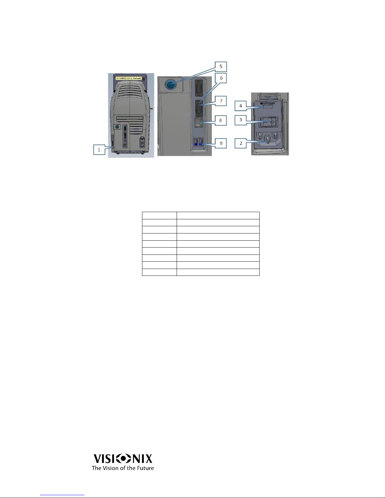
VX40 Rear View
Figure 3-2: VX40 Rear View
Table 3-2: VX40 Rear View Components
1
Printer Paper Door
2
Power Inlet
3
Main Power Switch
4
Fuse Compartment
5
Power Button
6
VGA Connector
7
Serial port RS-232
8
LAN Connector
9
USB Ports (x2)
Page 14
Equipment and Installation
VX40 User Guide
14 / 53
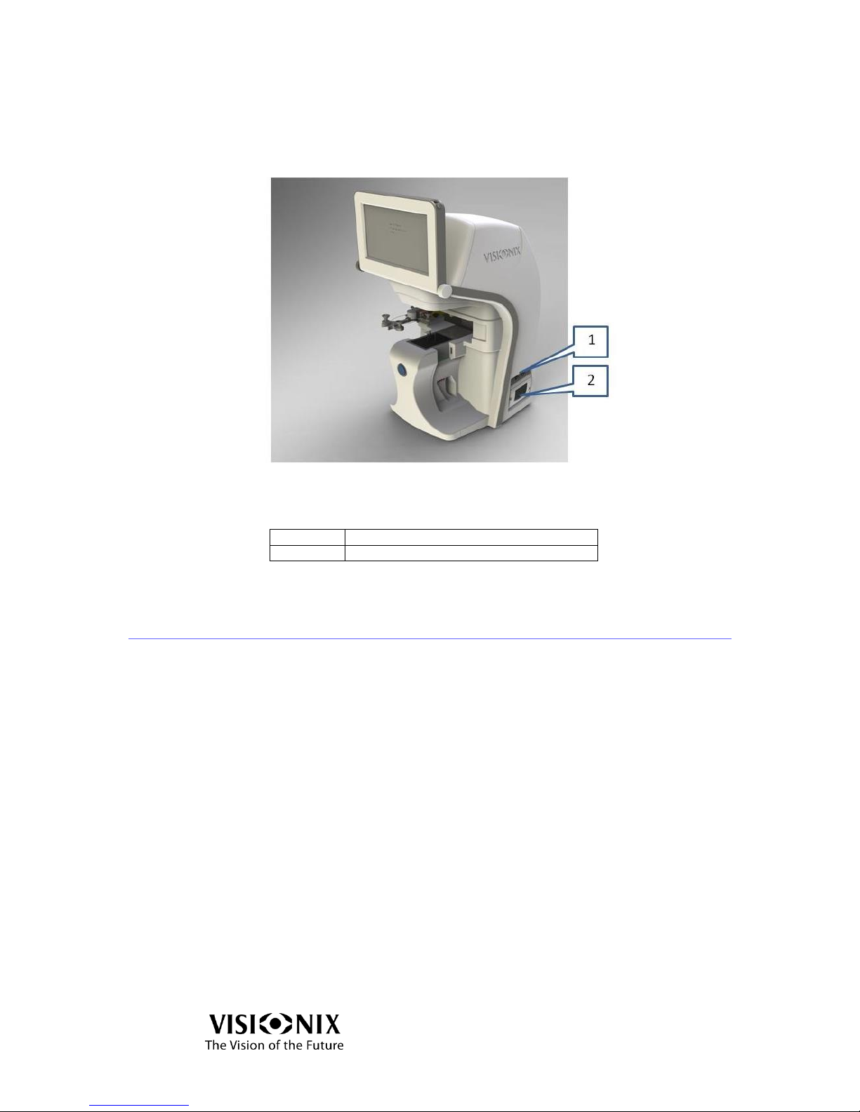
VX40 Side View
The side view illustrates the printer compartment of the device.
Figure 3-3: VX40 Side View
Table 3-3: VX40 Side View Components
1
Paper Door
2
Printer LED Indicator
3.3 Installation Procedures
Site Requirements
Prepare a clear desktop close to the wall power outlet.
Opening the Box
Open the carton with care.
Lift the protective top cover to uncover the accessories shipped as listed in the
packing list.
Page 15
Equipment and Installation
VX40 User Guide
15 / 53
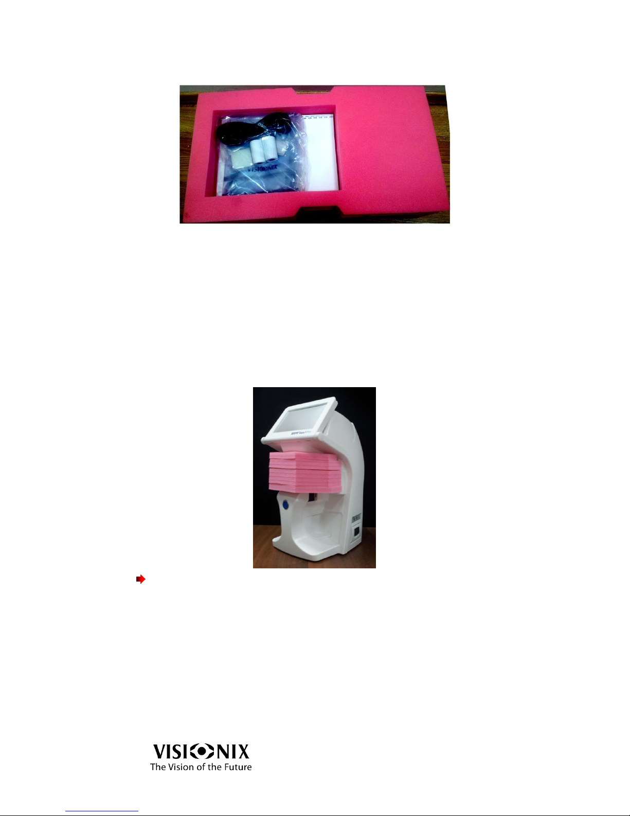
Figure 3-4: Top Cover Removed
Remove the accessories to uncover the VX40, which is packed in a protective
plastic bag.
Figure 3-5: Accessories Released
Take the VX40 out of the box and put it on the desk.
Lift the protective plastic bag to uncover the device.
The Frame Holder is secured by a protective foam.
Remove the protective foam to release the Frame Holder.
Important!
Do not grab or hold the monitor or the Frame Holder when extracting the device
from the box.
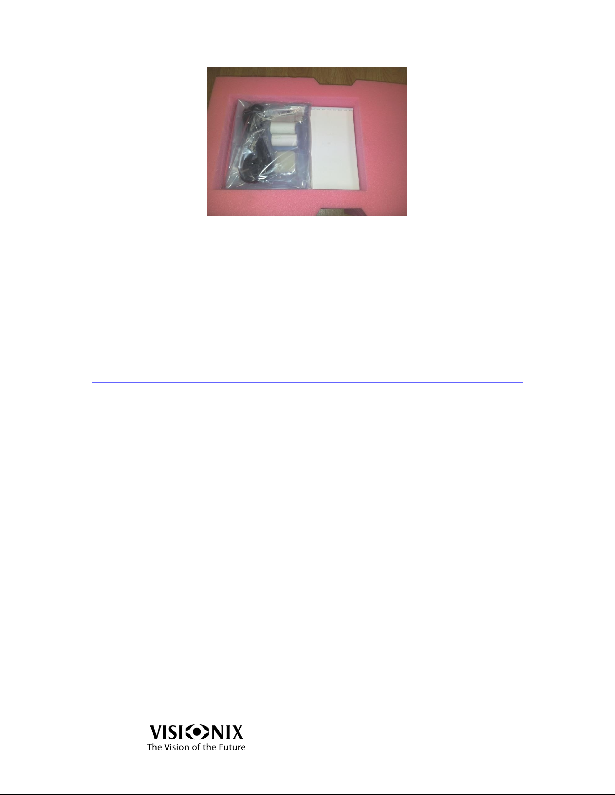
The accessories shipped with the device are packed in a plastic bag as illustrated
below.
Page 16
Equipment and Installation
VX40 User Guide
16 / 53
Figure 3-6: Accessories Bag
Electrical connection
Check that the power supply voltage corresponds to that required by the
equipment (see the identification label on the back of the unit).
Insert the connector of the cord into the power receptacle of the device.
Connect the power plague into the main wall outlet.
3.4 Starting and shutting down the device
Starting
Set the Main Power Switch to ON (Position 1).
Press the power button located at the rear of the VX40.
Wait until the software starts.
Shut Down
Press the power button located at the rear of the VX40.
Wait until the software shuts down.
Set the Main Power Switch to OFF (Position 0).
Page 17

Using the VX40
VX40 User Guide
17 / 53
4. Using the VX40
Page 18
Using the VX40
VX40 User Guide
18 / 53
4.1 General
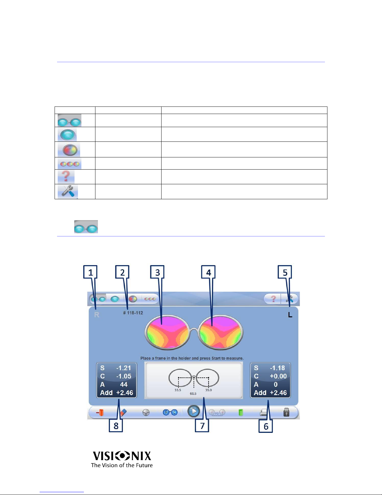
The device is operated by the application, which the user accesses by
touching the touch screen.
The upper toolbar allows to access to the different interfaces.
Table 4-1: Upper Toolbar
Icon
Designation
Description
Frame Interface
Initiates measurement of frame
Analyze Interface
Initiates analysis of the lens properties at any given point of a
preselected lens
Lens Interface
Initiates a measurement of lens without frame (cut or uncut
lens)
Compare Interface
Initiates comparison of measurements of several lenses
Help
Not applicable in this version
Tools Icon
Opens the settings or maintenance screen as applicable
4.2 Frame Interface
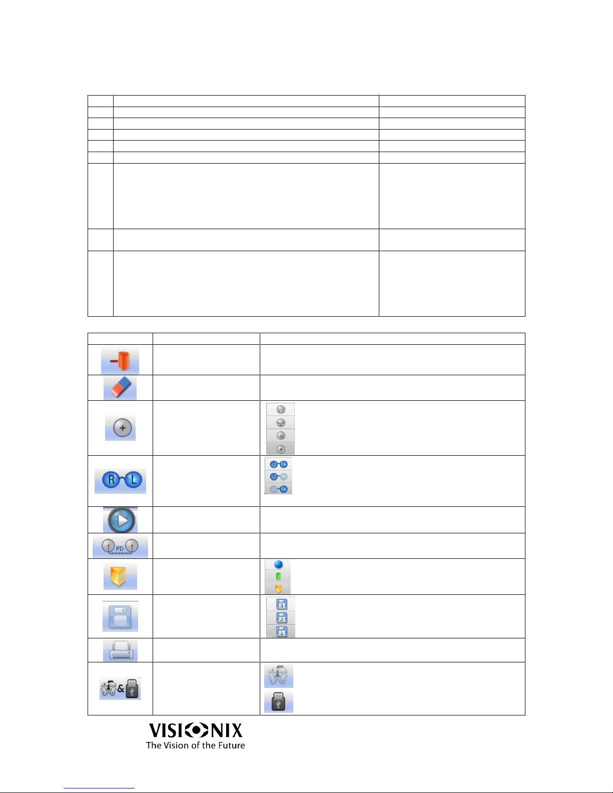
This interface is used to measure a frame.
Figure 4-1: Frame Interface – Results Screen
Page 19
Using the VX40
VX40 User Guide
19 / 53
Table 4-2: Screen Elements
No
Description
Notes
1
Right side indication
2 Job number
3 Lens map - right
4 Lens map - left
5 Left side indication
6
Measurement readout - left
Readout is printable:
S: sphere
C: cylinder
A: Axis
Add: add power between far
and near vision
7
P.D. readout
See Chapter on Pupil Distance
Measurements.
8
Measurement readout - right
Readout is printable:
S: sphere
C: cylinder
A: Axis
Add: add power between far
and near vision
Table 4-3: Frame Interface Toolbar
Icon
Designation
Description
Cylinder Convention
Selects Plus or Minus
Clear
Erases the result from the screen
Lens Type
Reading Lens
Multi-focal
B-Focal
Single Vision
Right / Left
Selects the right or left lens, or both
Play / Stop
Starts or stops measurement
Prism calculation
Manipulate the P.D. measurements.
Map type display
Sphere
Cylinder
Prism
Save results
Saves the measurement to enable comparison with
another measurement. If there is a saved
measurement, the memory icon will be yellow.
Print command
Generates printout of result as a ticket
Data Export
Send data to a phoropter or a computer.
Send data to a USB or a network.
Page 20
Using the VX40
VX40 User Guide
20 / 53
Pupil Distance Measurements
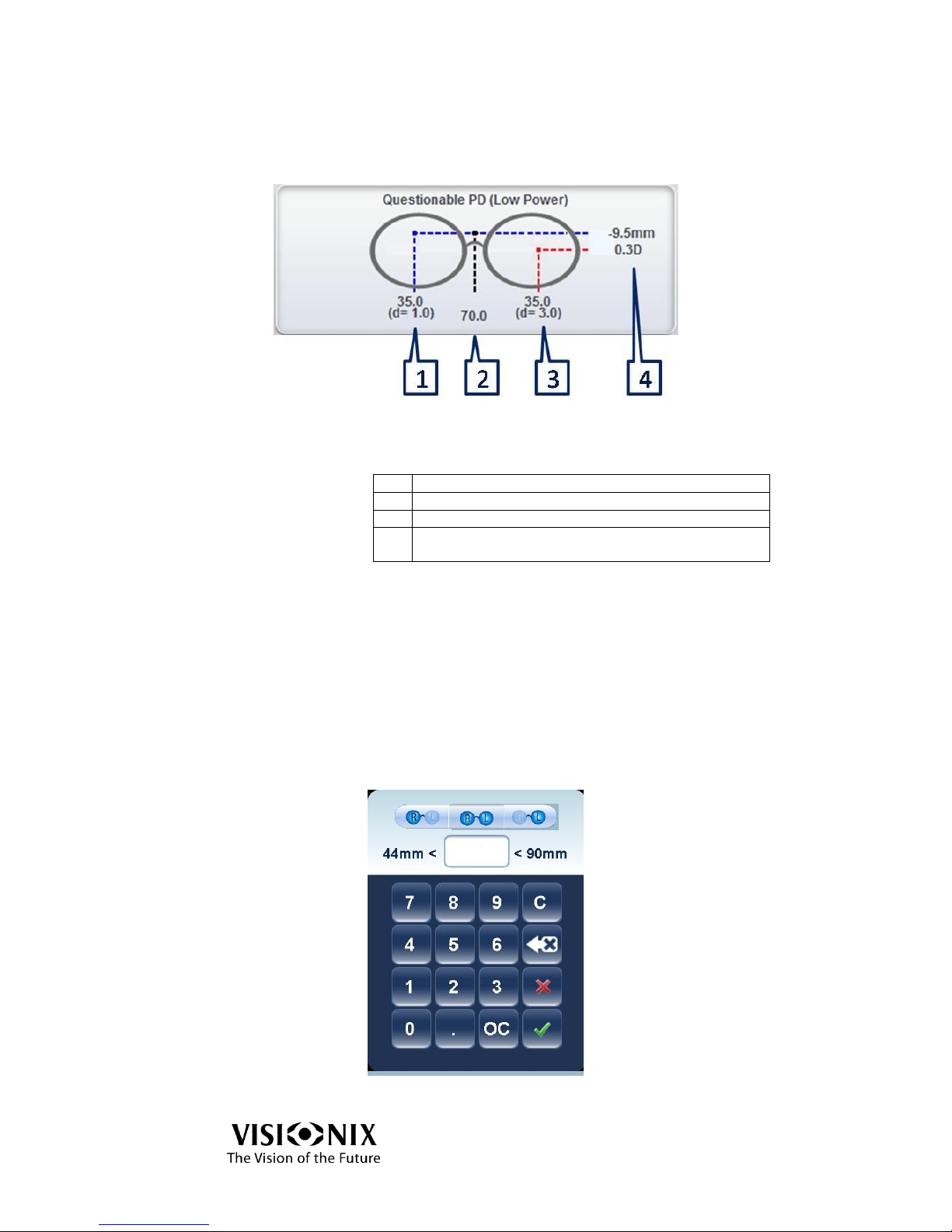
This interface displays the different P.D. measurements.
Figure 4-2: P.D. Mesurements Interface
Table 4-4: P.D. Measurements
1
Right P.D.
2
Total P.D.
3
Left P.D.
4
Net Vertical Prism (the difference in height between
the left and right optical centers.)
Note:
The net vertical prism displays the equivalent prismatic power in mm. It appears at
the side with the strongest equivalent power. The blue line represents the weakest
power, and red line represents the strongest power.
Prism Caluclation
This interface is used to manipulate the P.D. It displays the prism
automatically at this specific distance.
Figure 4-3: Prism Calculation
Page 21
Using the VX40
VX40 User Guide
21 / 53
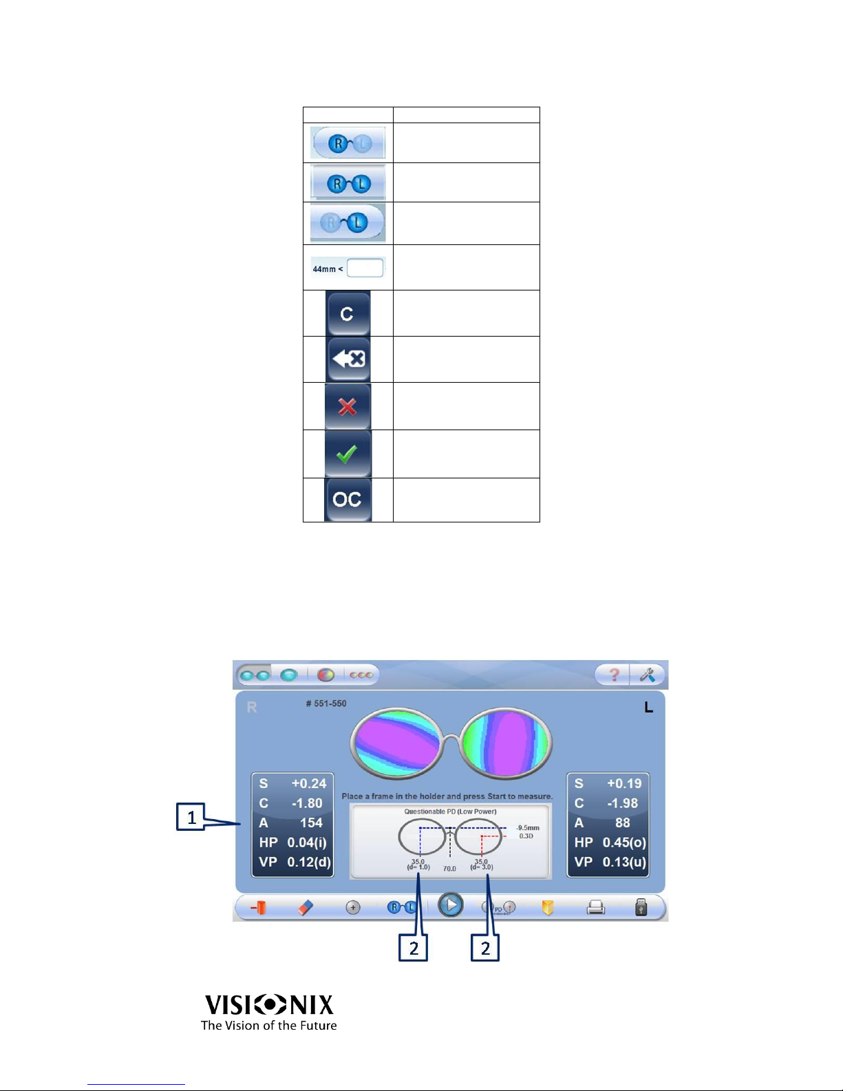
Table 4-5: Prism Calculation Toolbar
Icon
Description
Change right P.D.
Change total P.D.
Change left P.D.
Select P.D. according
to minimum and
maximum constraints
Cancel
Delete
Reject changes
Accept changes
Cancel changes
Note:
You can only carry out prism calculations for single vision and bifocal lenses.
Prism Calcluation Results
The following interface displays the results of a prism calculation.
Figure 4-4: Prism Calculation Results
Page 22
Using the VX40
VX40 User Guide
22 / 53
Table 4-6: Prism Calculation Results
No
Designation
Description
1
S, C, A, P, B
Readings at the selected location
2
D
Decentration
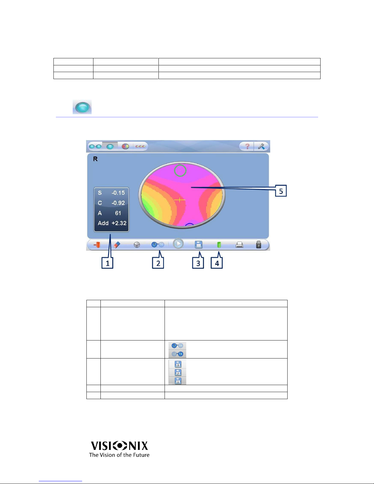
4.3 Analyze Interface
This interface is used to analyze the lens properties at any given point of a
preselected lens.
Figure 4-5: Analyze Interface
Table 4-7: Analysis Screen Elements
No
Description
Notes
1
Measurement readout
Readout is printable:
S: sphere
C: cylinder
A: Axis
Add: add power between far and near vision
2
Side selection
Right
Left
3
Save
Save the measurement to compare
with another one. If there is a saved
measurement, the memory icon will
be yellow on the lower toolbar.
4
Displayed Map
Sphere \ Cylinder \ Prism
5
Lens map
Display of the map of powers
In Analyze mode, the blue curve presents the near vision and the green one the far
vision. The cross represents the optical center of the lens.
Page 23
Using the VX40
VX40 User Guide
23 / 53
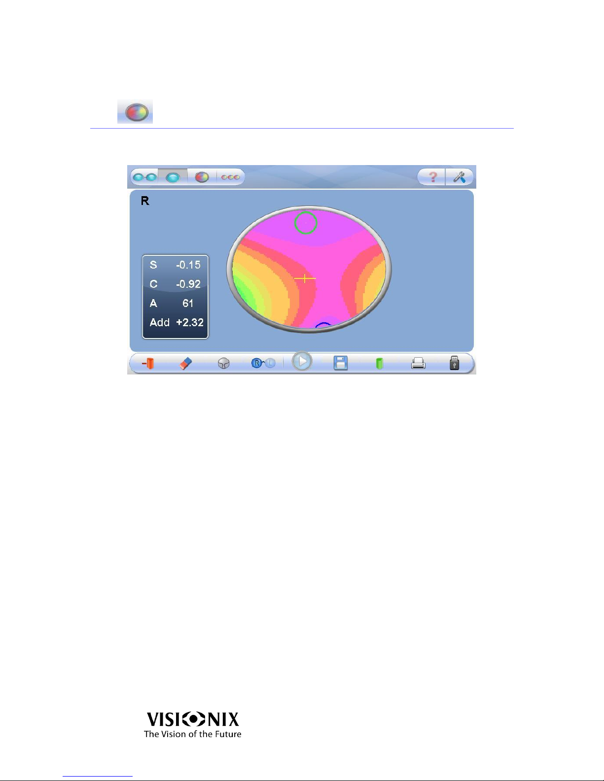
4.4 Lens Interface
This interface is used to initiate the measurement of lens without frame (cut or
uncut lens).
Figure 4-6: Lens Interface
The functions are the same as in analyze interface (see 4.3).
Page 24
Using the VX40
VX40 User Guide
24 / 53
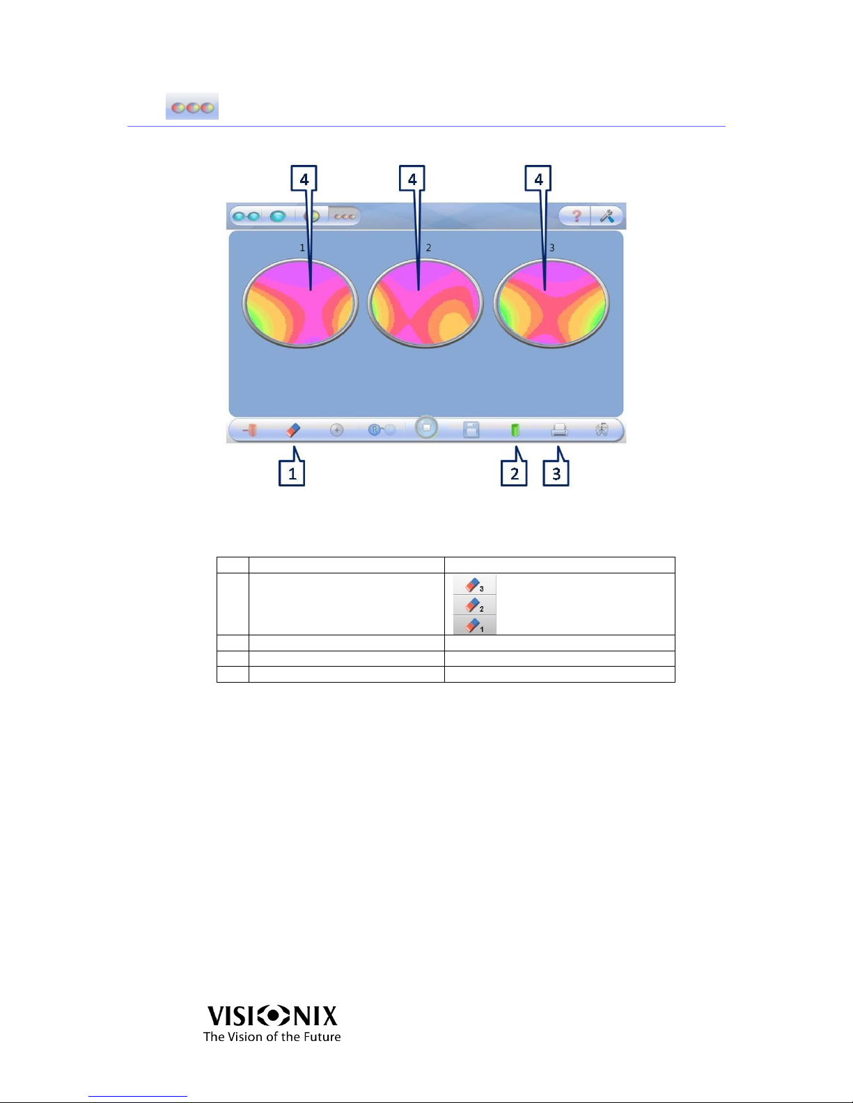
4.5 Compare Interface
This interface is used to compare the measurements of several lenses.
Figure 4-7: Analysis Screen
Table 4-8: Compare Screen Key Elements
No
Description
Notes
1
Clear
Erase measurement 3
Erase measurement 2
Erase measurement 1
2
Frame Chart Type Displayed
Sphere \ Cylinder \ Prism
3
Print
Printout of Tickets
4
Maps
Displays the Frame Chart
Page 25

Configuring the VX40
VX40 User Guide
25 / 53
5. Configuring the VX40
Page 26
Configuring the VX40
VX40 User Guide
26 / 53
5.1 Configuration Access
Click on Tools button .
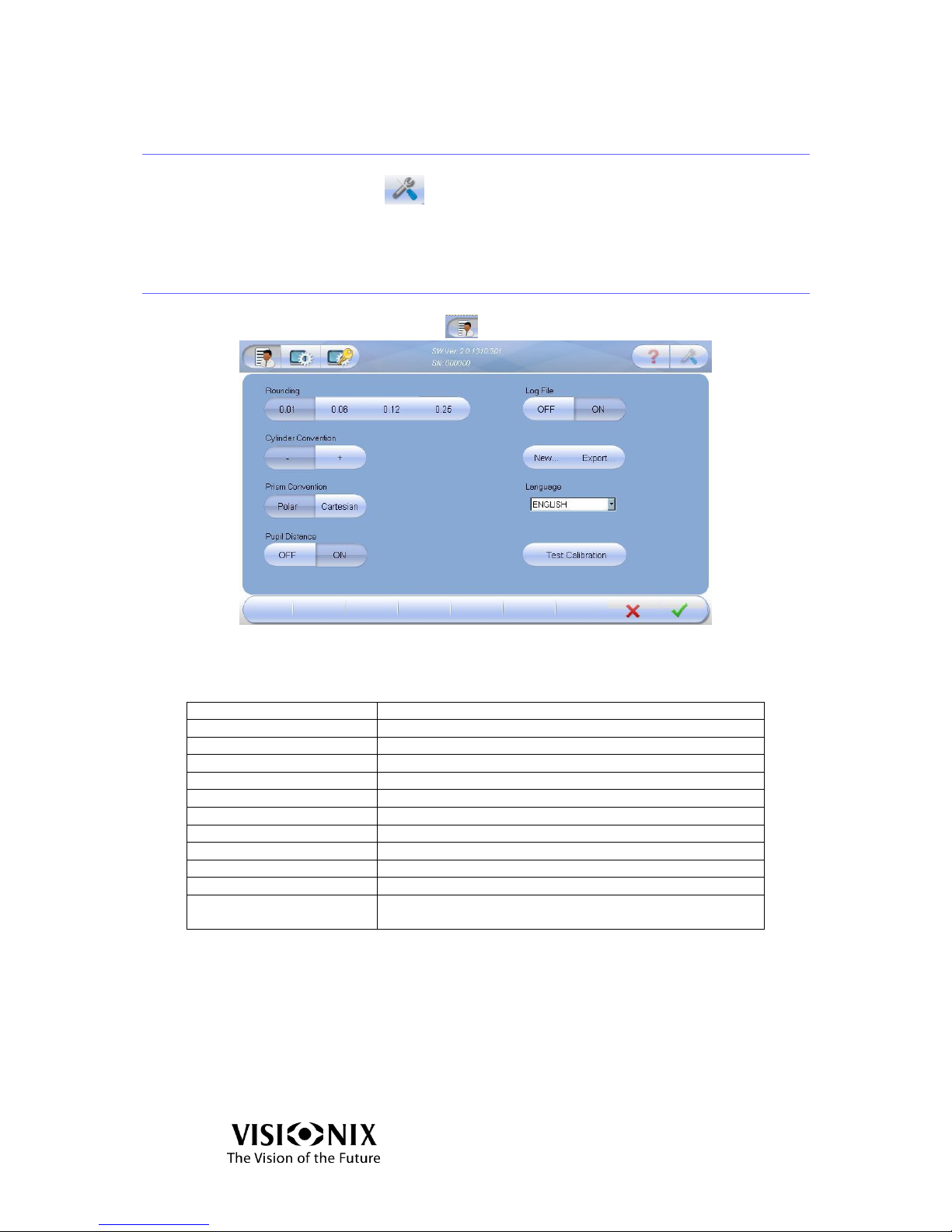
5.2 User Settings
Click on User Settings button
5-1: User Settings Screen
Table 5-1: User Setting Elements Key
Operation Name
Operation Description
Software Version
Current software version
Serial Number
The serial number of the product
Rounding
Show results with an accuracy of 0.01/0.06/0.12/0.25
Cylinder Convention
Minus / Plus
Prism Convention
Polar (Amp & Angle) / Cartesian (X,Y)
Pupil Distance
Display the distance of each pupil to the center.
Log File
Save the data in a file or create a new file.
New
Create new log file (delete data).
Export
Export log file to a USB.
Language
Change the language.
Test Calibration
Test if the instrument requires calibration, using the
supplied test frame.
Page 27
Configuring the VX40
VX40 User Guide
27 / 53
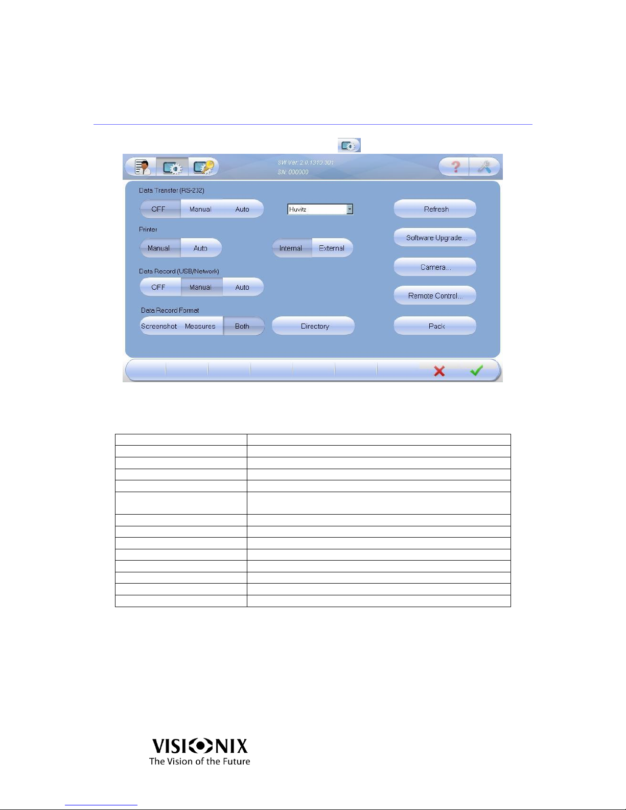
5.3 Advanced Settings
Click on the Advanced Settings button
5-2: Advanced Settings Screen
Table 5-2: Advanced Settings Screen Elements
Operation Name
Operation Description
Software Version
Current software version
Serial Number
The serial number of the product
Data Transfer (via RS-232)
Transfer the data to PC or phoropter etc.
Printer – Manual/Auto
Print automatically or manually
Printer – Internal/External
Print a screenshot of the Main screen from the VX40 or an
external printer
Data Record (USB/Network)
Export the data to a network or a USB
Data Record Format
Export a screenshot, an image or both
Directory
Select the directory where you want to store the data
Refresh
Optical refresh
Software Upgrade
Upgrade the software
Camera
View the camera image
Remote Control
Initiate remote diagnostics and opens TeamViewer
Pack
Prepare the instrument prior to packing it
Page 28
Configuring the VX40
VX40 User Guide
28 / 53
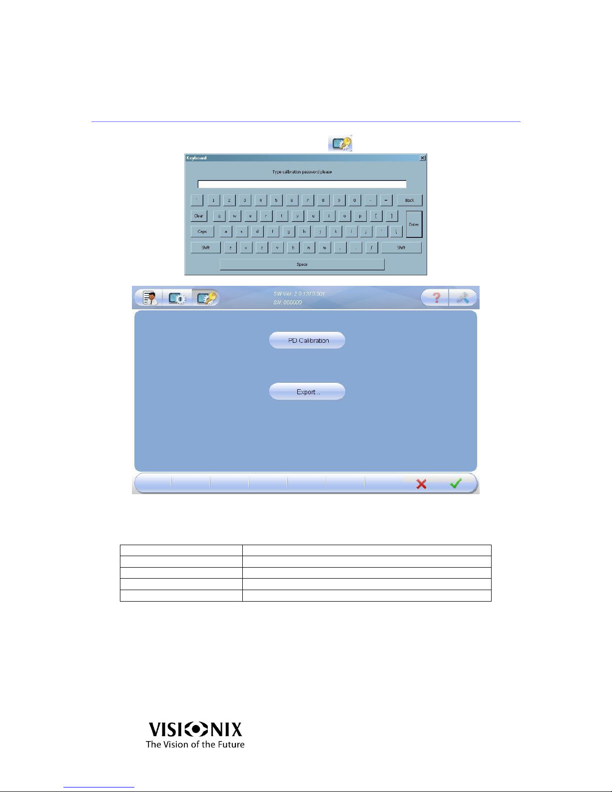
5.4 Technical Settings
Click on the Technical Settings button and click Enter
5-3: Technical Settings Screen
Table 5-3: Technical Settings Screen Elements
Operation Name
Operation Description
Software Version
Current software version
Serial Number
The serial number of the product
P.D. Calibration
Calibrate pupil distance
Export
Save system parameters
Page 29

How to?
VX40 User Guide
29 / 53
6. How to?
Page 30
How to?
VX40 User Guide
30 / 53
6.1 How do I measure a frame?
Go to frame interface
If the frame interface is not displayed:
Click on (frame interface button).
The frame holder moves to the center of the device.
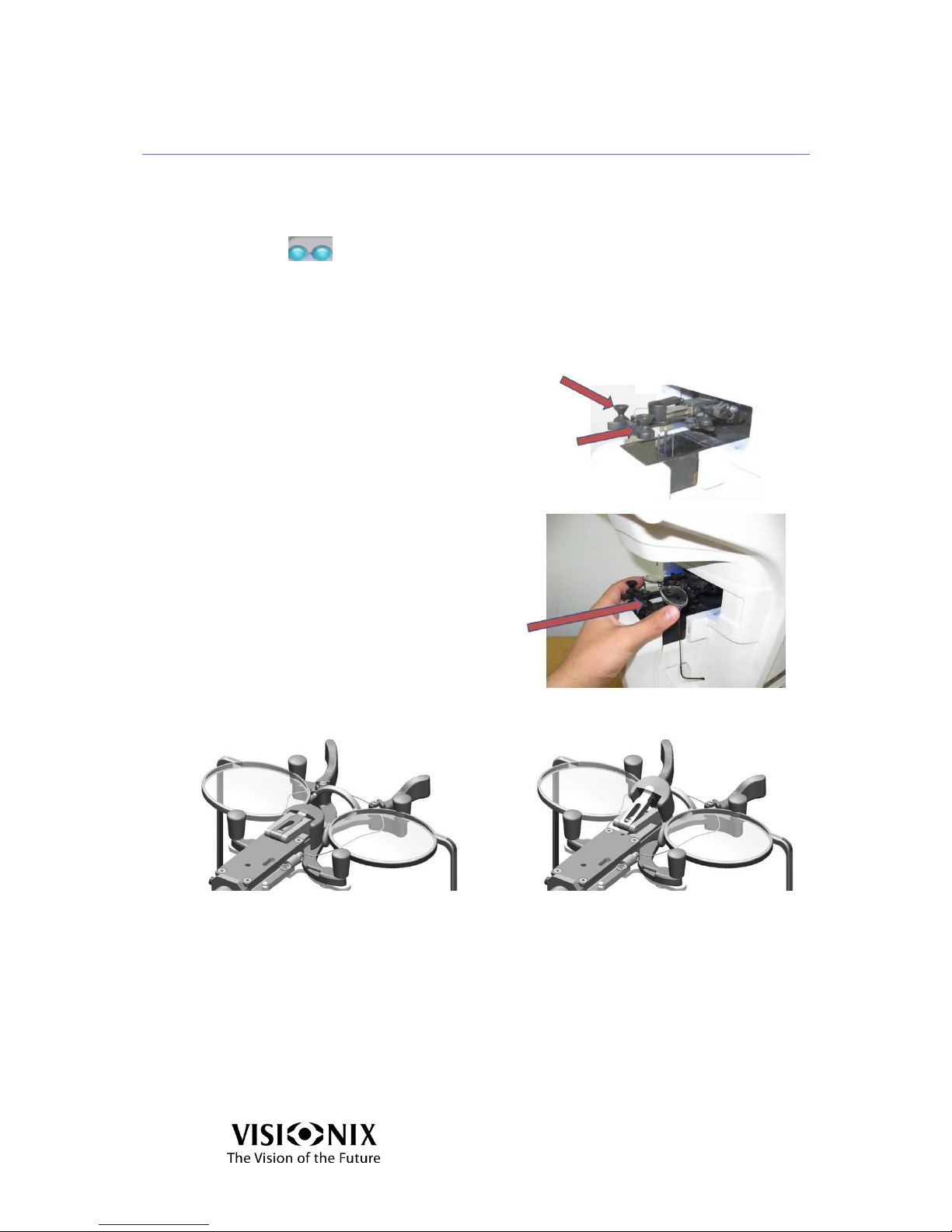
Place the frame
Position your fingers on either side
of the Frame Holder.
Push the sides of the Frame Holder
in the direction of the arrows until
you hear a “click”.
Place the frame in the holder by
pushing the knob in the direction of
the arrow.
Verify that the bridge of the frame is not higher than the level of the nose pad of
the Frame Holder.
Good
No good
Figure 6-1: Placing the Frame Holder
Page 31
How to?
VX40 User Guide
31 / 53
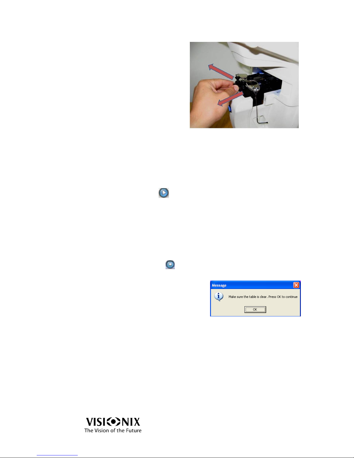
Release the holder in the direction
of the arrows until you hear a
“click”.
Select the option of measurement
Select the lens(es) you want to measure (right, left or both).
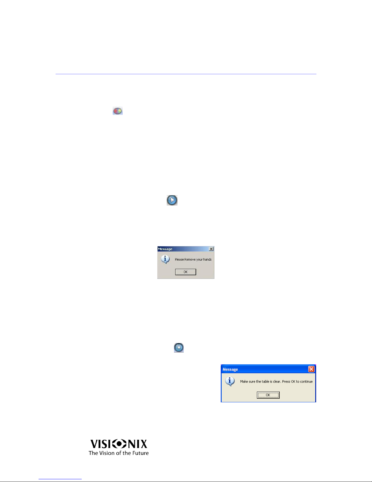
Start the measurement
Start the measurements:
Click on GO ( ),
Or press the measurement start/stop button.
The measurement is performed completely automatically.
Abort the measurement
To abort the measurement:
Stop the measurement.
Click on STOP ( )
Or press the measurement start/stop button.
Choose OK to skip the current measurement
and go to the main interface.
Extract the frame
Release the holder until you hear a “click”.
Extract the frame.
Page 32
How to?
VX40 User Guide
32 / 53
6.2 How do I measure a lens (without a frame)?
Select lens interface
If the lens interface is not displayed:
Click on (lens interface button).
The frame holder moves to the left of the device.
Place the lens
Place the lens verifying that the lens orientation is like the frame orientation (the
bottom of the lens on the device side).
Start the measurement
Start the measurements:
Click on GO ( ),
Or press the measurement start/stop button.
Press the Play button to move blocker (3 pins) downward to secure the lens
against the 3 static pins of the detector.
In the following message you are prompted to remove your hands:
Remove your hands and press OK.
The measurement has been taken and the lens is still fixed by the blocker.
Abort the measurement
To abort the measurement:
Stop the measurement.
Click on STOP ( )
Or press the measurement start/stop button.
Choose OK to skip the current measurement
and go to the main interface.
Release the lens
Press the Play button (the Go/Stop button) again.
Page 33
How to?
VX40 User Guide
33 / 53
6.3 How do I change the cylinder convention?
In the settings screen
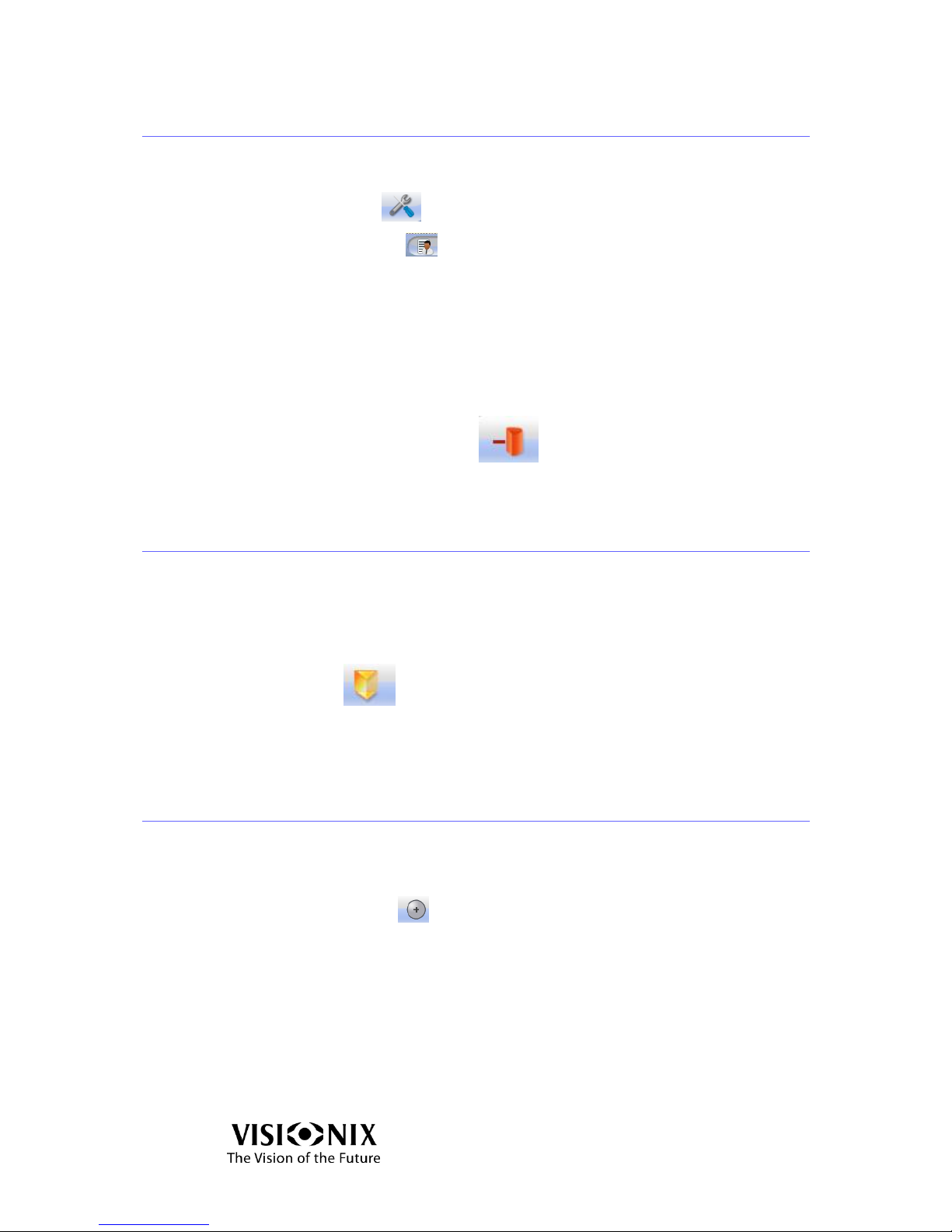
Click on Tools button
Click on Settings button
Change the cylinder convention (see also 5.2).
Note:
The convention you choose in the settings is the default convention when you start
the device. You can change the convention in other screens.
On the main screens
Click on Cylinder convention button
6.4 How do I change the map type?
Measured lenses can be displayed with different maps: sphere, cylinder and
prism. By default, the prisms map is displayed for single vision lenses and the
cylinders map for progressives.
To change the type of map:
Press the button .
Select the map you want to display.
6.5 How do I change lens type?
The VX40 detects the lens type automatically.
In case you need to change the lens type manually:
Click on Lens Type tool
The following popup menu is displayed:
Single Vision
B-focal
Multi-focal
Reading lens
Note:
Reading lenses are not detected automatically by the device; you have to impose
this type manually to effect measurement.
Page 34
How to?
VX40 User Guide
34 / 53
6.6 How do I clear data?
In compare interface
Click on Clear button
Select the data you want to clear.
In other interfaces
Click on Clear button
6.7 How do I analyze a lens?
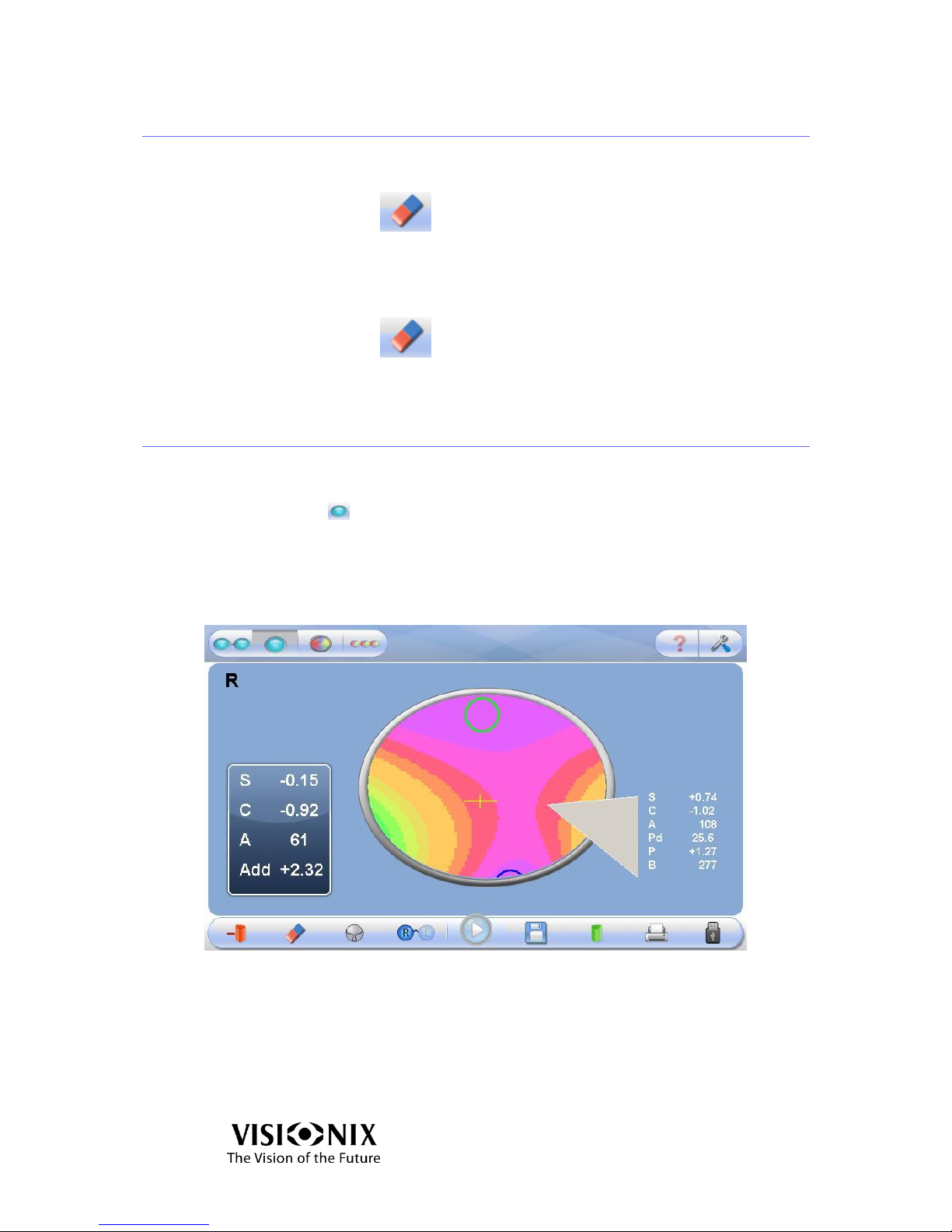
Go to analyze interface
Click on icon ( ).
Or double-click on the desired side of the frame.
See local values
Click on the area you want to know the local value.
Figure 6-2: Measurement readout for a single point
Page 35
How to?
VX40 User Guide
35 / 53
6.8 How do I print out results?
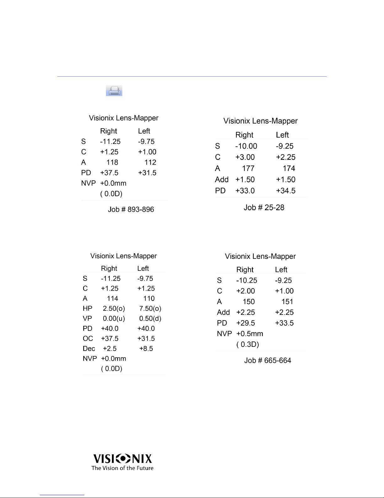
Click Print button .
Single Ticket Printout (no PD manipulation)
Multi-focal (progressive) Ticket Printout
Single Ticket Printout (after PD manipulation)
Bifocal Ticket Printout
Figure 6-3: Ticket Printout Sample
Page 36
How to?
VX40 User Guide
36 / 53
6.9 How do I send data?
Preparation
Note:
The preparation should be done by a technician.
Connection
Connect the VX40 to the target device (phoropter, computer) using a serial cable
connection or via a wireless connection like:
RS-232 cable.
Bluetooth connection via RS232.
Settings
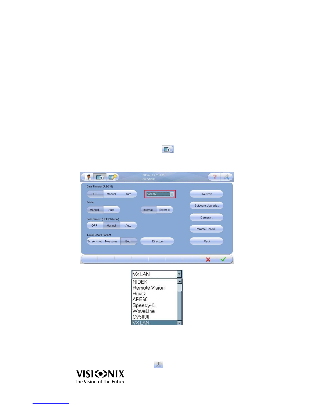
Click the Advanced Settings button .
Select a Data Transfer option (manual or auto).
Select a device from the combo box.
Figure 6-4: Data Transfer Screen
Send the data
Do your measurement.
Click on the Data Transfer button .
Page 37
How to?
VX40 User Guide
37 / 53
Note:
Depending on the setup configuration, you may be required to click the Data Export
button before selecting the Data Transfer button.
After the “handshake” between the two devices occurs and data transfer begins, a
beep will be emitted.
6.10 How do I export data?
Connection
If you are using a USB, connect it to the back of the VX40. See figure 3-2.
Settings
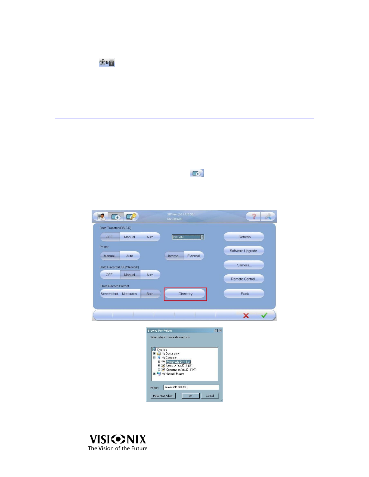
Click the Advanced Settings button .
Select a Data Record option (manual or auto).
Select the Data Record type (screenshot, images or both).
Click the Directory button to select where you want to store the data.
Figure 6-5: Browse For Folder Screen
Page 38
How to?
VX40 User Guide
38 / 53
Send the data
Do your measurement.
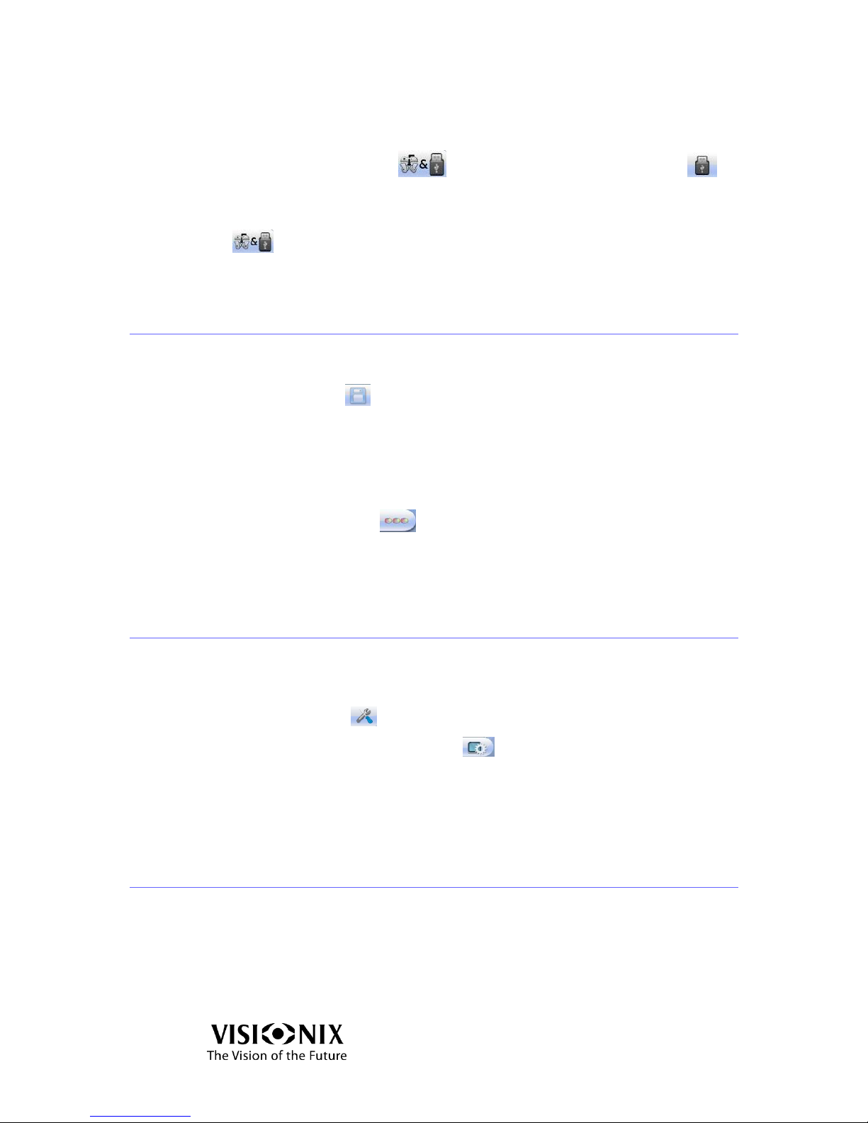
Click the Data Export button followed by the Data Record button .
Note:
Depending on the setup configuration you may be required to click the Data Export
button before selecting the Data Record button.
6.11 How do I compare lenses?
Save the data
Click on Save button
The measurements can be saved both in Analyze mode and in Single Lens mode.
You can save and compare up to three lenses.
Go to analyze interface
Click on Compare button ( ).
The saved results are displayed.
6.12 How do I upgrade the software?
Download the new version to a disk-on-key.
Insert the disk on key into the USB port of the device.
Click on Tools button
Click on Technical maintenance button
Click on Software Upgrade button
The software download procedure starts.
6.13 How do I refresh the system?
Notes:
The system needs to be reset only if there are problems of measurements.
Verify that the detector is clean.
Verify that the Frame Holder is empty and is in the open state (home position).
Page 39

How to?
VX40 User Guide
39 / 53
Click on Tools button .
Click on Technical maintenance button .
Click on Refesh button.
The system resets.
Page 40
How to?
VX40 User Guide
40 / 53
6.14 How do I pack the system?
Click on Tools button .
Click on Technical maintenance button .
Select the "Pack" button and follow the on-screen instructions.
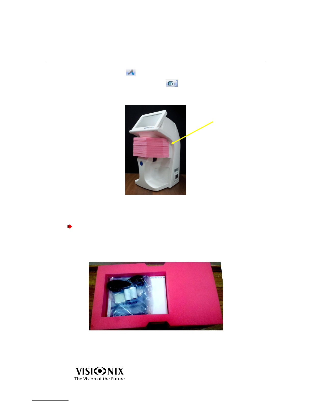
Place the protective foam of the holder.
Figure 6-5: Accessories released
Cover the VX40 with the protective plastic bag.
Place the VX40 in its package.
Important!
Do not grab or hold the monitor or the frame holder when inserting the device
from the box.
Place the accessories cover on top of the VX40 as illustrated below.
Figure 6-6: Top Cover Removed
Protective
foam
Page 41

What should I do if … ?
VX40 User Guide
41 / 53
7. What should I do if … ?
Page 42
What should I do if … ?
VX40 User Guide
42 / 53
7.1 There is a warning message
The warning messages listed below advice the user of a failure and point to a
specific action that can be taken to clear the failure condition.
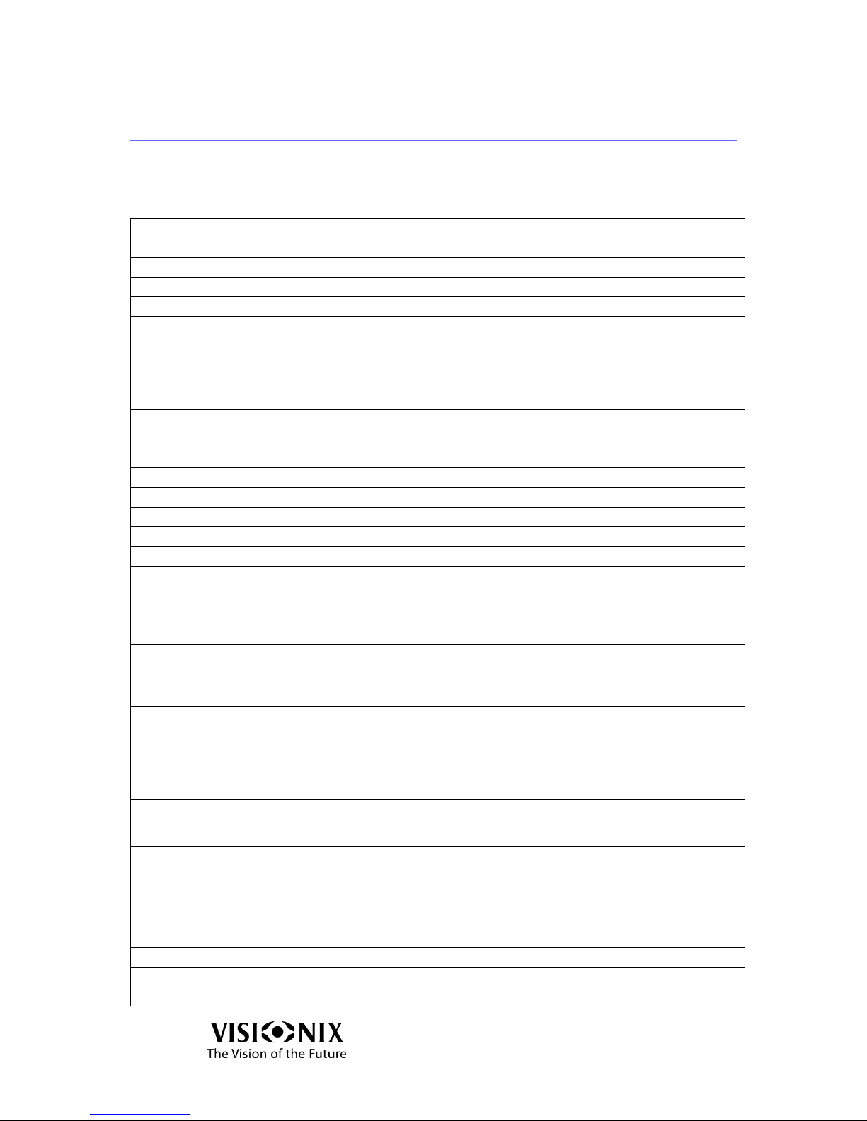
Message
Action
Creating Default Machine Parameters
Call technical support.
Please Calibrate The Machine
Call technical support.
Grabber Error
Restart. If this doesn't help, call technical support.
Communication Error
Make sure you have selected the correct protocol (see 6.9)
Failed To Analyze
Happens when the device fails to measure a lens.
Start again the measurement.
If this doesn't help, start a measurement without lenses and
start again with the lenses.
If this doesn't help, restart the device.
If this doesn't help, call technical support.
I/O Controller Error
Restart. If this doesn’t help, call technical support.
COM Port Error
Restart. If this doesn’t help, call technical support.
Shutter Error
Restart. If this doesn’t help, call technical support.
Lamp Error
Restart. If this doesn’t help, call technical support.
Blocker Error
Restart. If this doesn’t help, call technical support.
Backlight Error
Restart. If this doesn’t help, call technical support.
Application Internal Error
Restart. If this doesn’t help, call technical support.
Motors Controller Error
Restart. If this doesn’t help, call technical support.
Failed to Move
Restart. If this doesn’t help, call technical support.
Cannot Load File
Call technical support
Failed to Initialize. Please Restart.
Restart. If this doesn’t help, call technical support.
Cannot Save File
Restart. If this doesn’t help, call technical support.
To maintain maximum accuracy,
periodical calibration recommended,
please remove the frame and press
OK.
Follow the instructions as the device performs an automatic
recalibration.
The new Reset image differs strongly
from previous Reset. Do you want to
save the new Reset?
Make sure no frame is in the Frame Holder, clean the
detector and retry.
If this error still displays, accept.
Not an optimal reset. Please use Clean
Wizard, and if problem repeats,
replace window. Accept Anyway?
Clean, repeat and accept.
Measurement Failed
Happens when the instrument fails to measure a lens. If this
happens constantly even on different spectacle frames,
restart. If this doesn't help call technical support.
Calibration Failed.
Clean, repeat and accept.
Grabber Error
Restart. If this doesn’t help, call technical support.
The upgrade version not found.
#Ensure the 'Disk on key' is correctly
inserted into USB port and press
'Retry'.
Make sure you have setup.exe in the root of your disk on
key.
No Reset
Check out the reset flow (see 6.13).
Unsupported Lens Type
The required lens type is not supported.
Murky Image (Window Covered?)
Restart. If this doesn’t help, call technical support.
Page 43
What should I do if … ?
VX40 User Guide
43 / 53
The shutter limit sensors may be
defective.
Restart. If this doesn’t help, call technical support.
Failed to initialize the Camera. #You
should call technical support. Would
you like to go Offline?
Restart. If this doesn’t help, call technical support.
Failed to initialize the Vx Controller.
#You should call technical support.
#Would you like to go Offline?
Restart. If this doesn’t help, call technical support.
Failed to analyze lens type
Retry.
Severe Error. Call technical Support
Call technical support
Questionable P.D. (Low Power)
Low power lens. The pupil distance measurement may not
be reliable.
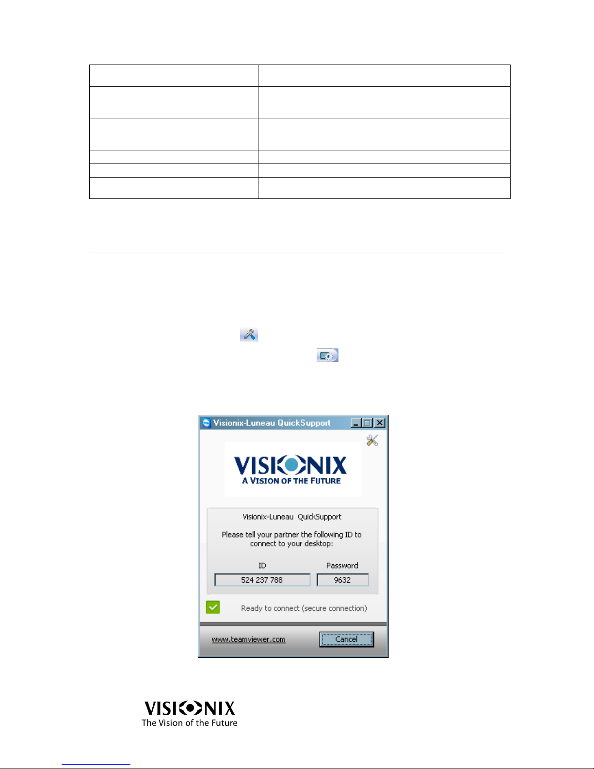
7.2 The technician needs remote diagnostics
The remote diagnostics allow the technician to connect the device at distance
for some technical operations (for example: software update).
To enable remote control:
Connect the device to internet
Click on Tools button
Click on Technical maintenance button
Click on Remote control button
Type the password using the popup keyboard
The TeamViewer application starts.
Figure 7-1: TeamViewer Screen
Provide the ID and password to the technician.
Page 44
What should I do if … ?
VX40 User Guide
44 / 53
7.3 The system stops, or if malfunctions are observed
Reset the system (see 6.13).
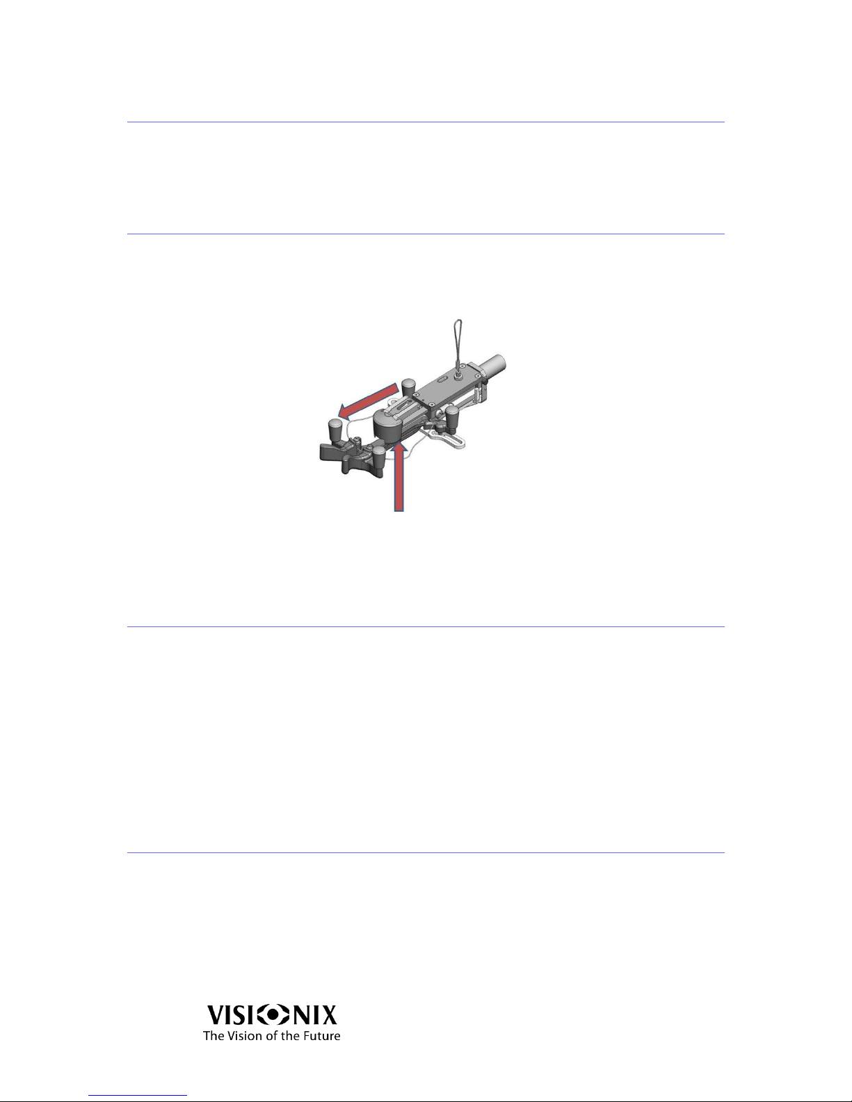
7.4 The nose of the frame holder is blocked
If the nose of the Frame Holder blocks:
Lift the nose gently and pull it toward the front.
Figure 7-2: Frame Holder Nose
7.5 I got a wrong measurement on trial lenses
Verify that the planest surface is on the top.
If this doesn’t help,
Reset the system (see 6.13) and restart the measurement.
Note:
Verify the Power Mapping Specifications listed in Table 9-3 match your
requirements.
7.6 I get wrong measurements
Go into settings mode (see 5.2).
Select the "Test Calibration" button.
Place the test frame in the holder and follow the on-screen instructions.
Page 45

Maintenance
VX40 User Guide
45 / 53
8. Maintenance
Page 46
Maintenance
VX40 User Guide
46 / 53
8.1 General
Important!
Switch off and unplug the VX40 before cleaning.
8.2 Cleaning
Clean the VX40 daily using a clean cloth before turning it on.
Clean the optical detector and the collimation lens as well. The collimation lens is
installed above the blocker.
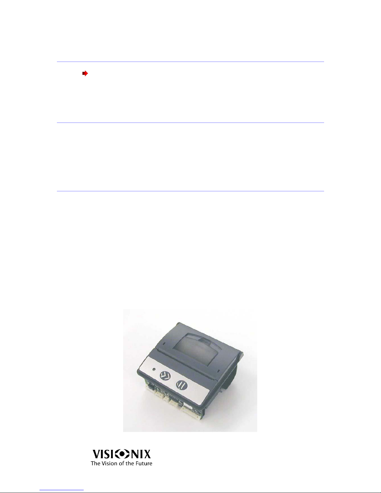
8.3 Printer paper replacement
The printer is mounted on the side of the VX40. If the paper roll is used up, the
Printer LED indicator blinks.
To change the paper roll:
Pull the lever until the cover is released from its locking position. To avoid
damaging the lever, do not use excessive force.
Open the cover.
Extract the used-up paper roll.
Insert a new paper roll.
Pull the paper towards the tear bar from one side to the other.
Close the cover. Press on both sides of the cover simultaneously.
Verify that the Printer LED indicator light is steady.
Figure 8-1: Printer – Top View
Page 47

Maintenance
VX40 User Guide
47 / 53
8.4 Fuse Replacement
The fuse holder is mounted above the power switch at the rear of the VX40.
In the fuse holder are two fuses of 2 Amperes.
To replace the fuses:
Open the fuse holder by means of a screwdriver.
Extract the fuse holder.
Change both fuses.
Insert the fuse holder into position and press it carefully.
Figure 8-2: Fuse Holder
8.5 Cap Replacement
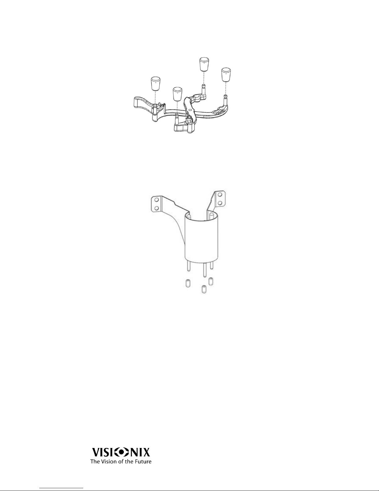
Protective caps are installed on three components near the Frame Holder as well on
the bottom of the device. These components are used to secure the frames (or lens)
during the measurement.
The caps have to be replaced when they are worn out; otherwise the lens may be
scratched.
The location of the three components near the Frame Holder is illustrated below.
You can release the caps by hand or by means of long-nose pliers.
Before the replacement
Verify that the device is ON and operational.
Verify that the holder is empty.
Page 48
Maintenance
VX40 User Guide
48 / 53
Holder Caps Replacement
Figure 8-3: Holder Caps
Remove the worn-out caps from the holder.
Replace them with new ones.
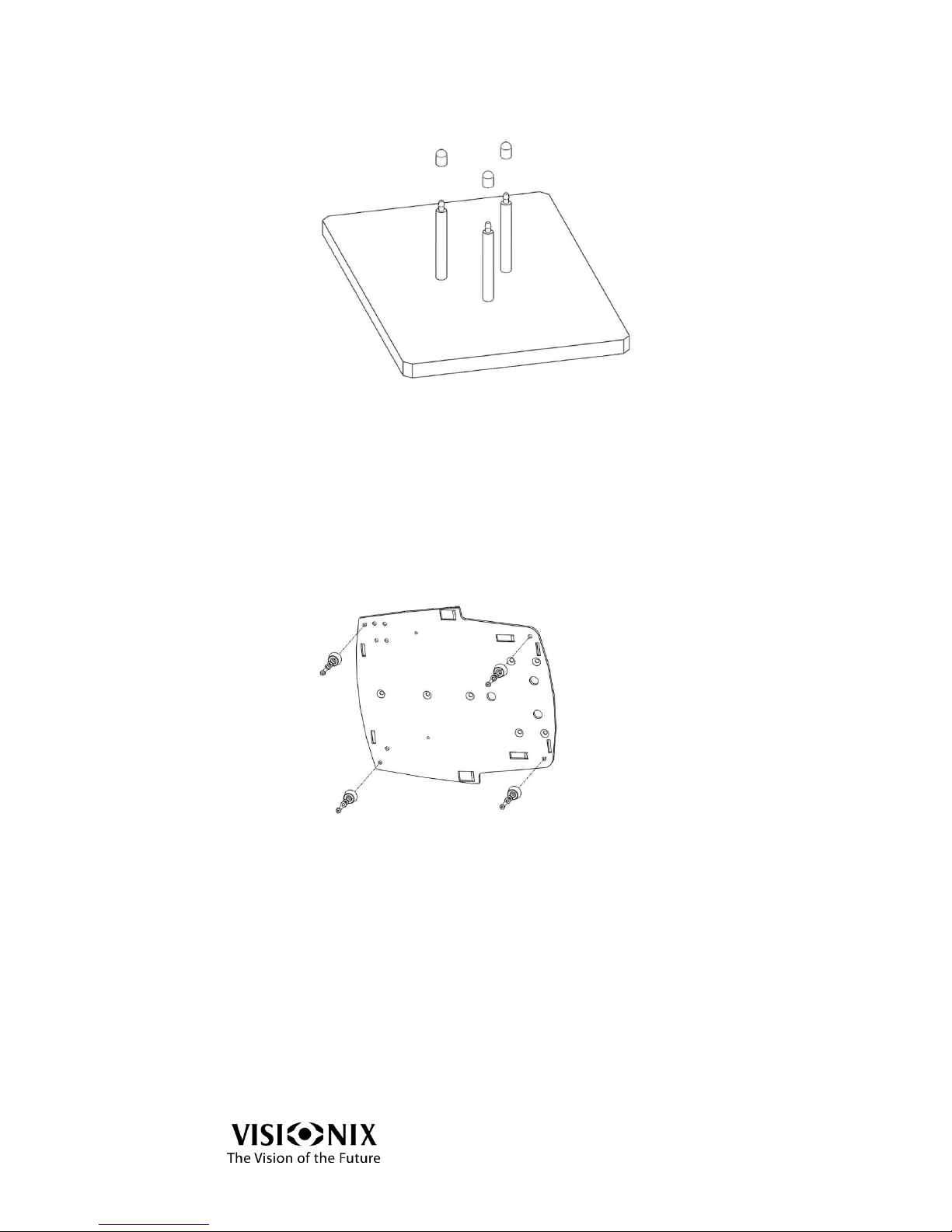
Blocker Caps Replacement
Figure 8-4: Blocker Pins and Caps
The blocker is located above the holder and moves downward when measurement
procedures start.
Move the holder leftward and close the arms of the holder.
Remove the worn-out caps from the pins by hand.
Put the new caps on the pins by hand.
Ensure that the pins do not move upward (you may use long-nose pliers to
secure the pins).
Verify that the caps are properly installed.
Return the holder to its normal position.
Page 49
Maintenance
VX40 User Guide
49 / 53
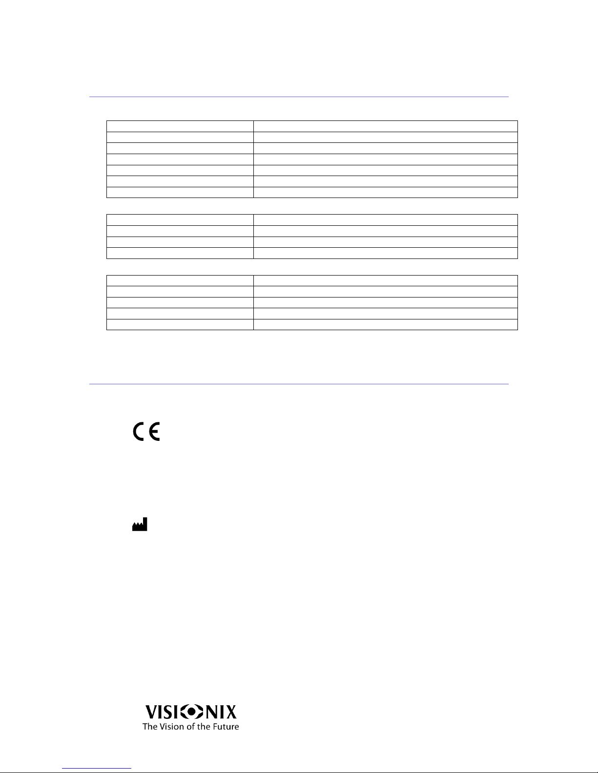
Detector Caps Replacement
Figure 8-5: Detector Pins and Caps
The static detector is located below the holder to secure the frame or the lens.
Remove the worn-out caps from the pins by hand.
Put the new caps on the pins by hand.
Verify that the caps are properly installed.
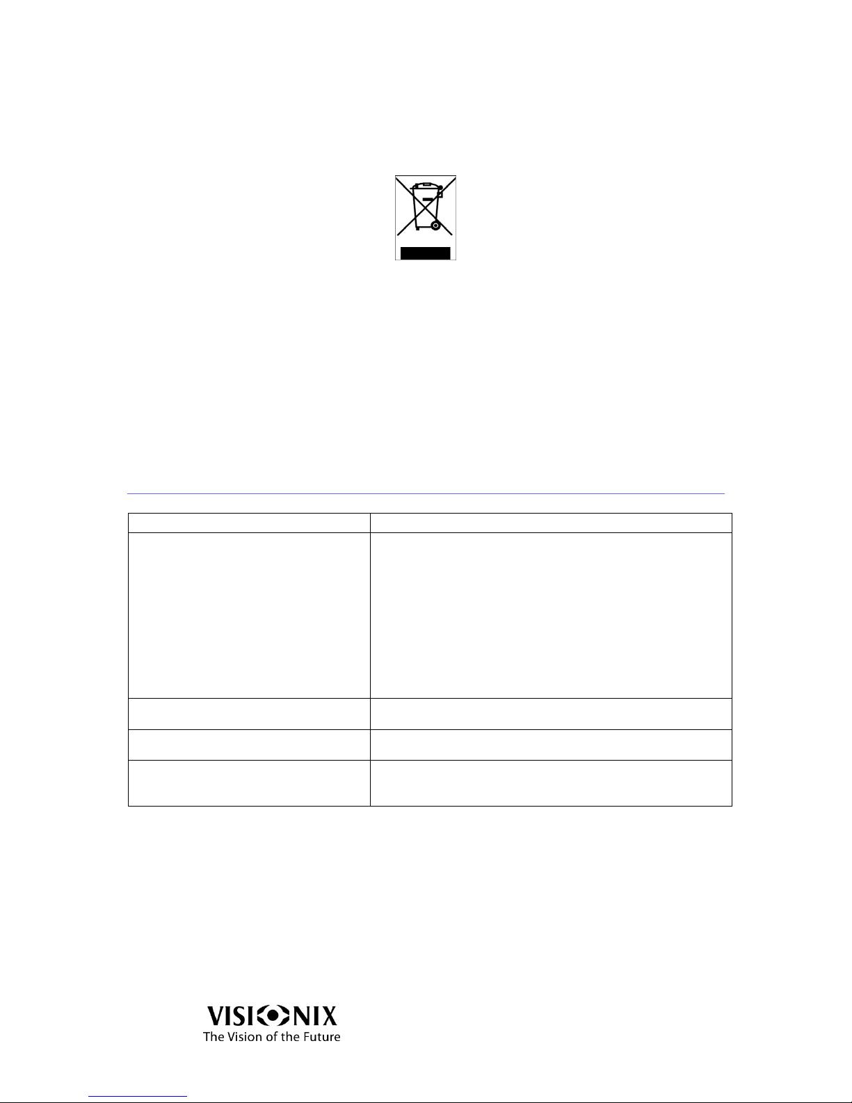
Base Caps Replacement
Figure 8-6: Base Caps Replacement
The base of the device is protected by rubber caps.
Turn the main power switch OFF and disconnect the device from the main wall
outlet.
Use an LN key: 2.5 millimeter to release the fastening nuts.
Turn the device on its side.
Unscrew the nuts and release the washers fastening the caps.
Place the new caps in position.
Insert the nuts and washers to fasten the caps.
Fasten the nuts with an LN key: 2.5 millimeter.
Page 50

Appendices
VX40 User Guide
50 / 53
9. Appendices
Page 51
Appendices
VX40 User Guide
51 / 53
9.1 Specifications
Table 9-1: Device Specifications
Height
455mm (17.9 inches)
Length
240mm (9.4 inches)
Width
220mm (8.6 inches)
Weight
9.1Kg (20 lbs.)
Power Source/Consumption
115/230V – 50/60 Hz 0.7 Ampere max.
Operating Temperature
10°C (50°F) to 40°C (104°F); Relative Humidity 30%-85%
Storage Temperature
10°C (50°F) to 60°C (140°F); Relative Humidity below 70%
Table 9-2: General Specifications
Display Touch Screen
(800 x 480)
Color LCD
LCD/16M, 7’’
Printer
Built-in BW - External color available
Operating System
Windows XP
Table 9-3: Power Mapping (Wave Front) Specifications
Spherical Power Range
-15..+10 D (step 0.01, 0.06, 0.125, 0.25 D)
Cylinder Power Range
0..10± xx D (step 0.01, 0.06, 0.125, 0.25 D)
Axis
0~180° (step 1 degree)
Addition power
0~± 3.5 D (step 0.01, 0.06, 0.125, 0.25 D)
Prism power
0~± 10 Δ (step 0.01d, … Δ)
9.2 Conformity with International Standards
Directives and standards
2006/95/EC Directive
2004/108/EC Directive
Manufacturer
LUNEAU SAS
1, Avenue de Malaguet
28360 PRUNAY LE GILLON
France
Page 52
Appendices
VX40 User Guide
52 / 53
Waste Electrical and Electronic Equipment (WEEE) Directive
Luneau SAS is registered as manufacturer by the French Agency, ADEME, for the
2002/96/CE, 2002/96/CE and 2003/108/CE directives.
This symbol is located on the VX40 and indicates that the equipment consists of
electronic assemblies and other components that may be subject to Directives
2002/96/EC, 2003/108/EC and 2002/95/EC of the European parliament, which
advises that electrical and electronic devices must not be disposed of as normal
domestic refuse. In order to prevent environmental risks or endangerments by nonprofessional disposal, the disposal of this product, including any accessories, must
comply with valid practices as outlined in Directives 2002/96/EC, 2003/108/EC and
2002/95/EC and local regulations. All electronic components and systems should be
returned to Original Manufacturer for disposal.
9.3 Glossary of Terms
Term
Explanation
Pupillary Distance
Pupillary Distance (P.D.) or interpupillary distance (I.P.D.) is
the distance (the industry standard is to measure in
millimeters) between the centers of the pupils in each eye.
This measurement is used when preparing to make
prescription eyeglasses. Positioning lenses correctly in
relation to the center of the pupils is especially important for
higher powered lenses due to the location of the optical
center of the lenses. It can also be relevant to binoculars:
they must be adjusted to suit the user's I.P.D.; and the
minimum allowed by some binoculars is still too great for
people with a small I.P.D.
Spherical Aberration
An aberration that can occur in optical systems when rays
are traced after reflection.
Cylindrical Lens
A lens with one face a portion of the curved surface of a
cylinder
Reflection
The process occurring when light strikes the surface of
separation of two different media such that some is thrown
back into the original media.
Page 53

Appendices
VX40 User Guide
53 / 53
9.4 Contact information
Deutschland
Buchmann Deutschland GmbH
Im Taubental 12, 41468 Neuss
Tel: (+49)2131 / 7523 50
Fax: (+49)2131 / 7523 704
Email: [email protected]
España
BRIOT WECO SPAIN
Calle Corominas 7, Planta 4, 08902 HOSPITALET DE LLOBREGAT
Tel: (+34) 93 298 07 37
Fax: (+34) 93 298 05 55
Tel S.A.T: (+34) 90 210 40 92
France
LUNEAU SAS
1, avenue de Malaguet, 28360 PRUNAY LE GILLON
Tel: (+33)2 37 25 25 25
SAV: (+33)2 37 25 25 37
Fax: (+33)2 37 26 75 99
Email: [email protected]
Italia
BRIOT WECO ITALIA
Via Zante 14, 20138 MILANO
Tel: (+39)2 55 41 31
Fax: (+39)2 55 41 32 43
Portugal
BRIOT WECO PORTUGAL
Av. Eng÷ Duarte Pacheco. Emp. das Amoreiras. Torre II.13÷A. LISBOA
Tel: (+35)1 214 170 225
Fax: (+35)1 214 170 227
Linha Verde: 800 205 142
USA
BRIOT USA
5251 Shiloh Road - Bldg A, CUMMING, GA 30040
Tel: (800) 292-7468
Export Technical Support
Luneau Technology Operations
2, rue Roger Bonnet, 27340 PONT DE L'ARCHE
Tel: (+33) 232 989 132
 Loading...