

Visionis VS-AXESS-4DLX, VS-AXESS-2ETL, VS-AXESS-2DLX, VS-AXESS-4ETL Installation Manual

Two Door Access Controller Panel
Board TCP/IP Wiegand with Software
and Power Supply Included 100,000
Users
VS-AXESS-4DLX
Installation Manual
1

User Manual
COPYRIGHT © Visionis Technology.
ALL RIGHTS RESERVED.
Any and all information, including, among others, wordings, pictures, graphs are the properties of
Visionis Technology or its subsidiaries (hereinafter referred to be “Visionis”). This user manual
(hereinafter referred to be “the Manual”) cannot be reproduced, changed, translated, or distributed,
partially or wholly, by any means, without the prior written permission of Visionis. Unless otherwise
stipulated, Visionis does not make any warranties, guarantees or representations, express or implied,
regarding to the Manual.
About this Manual
The Manual includes instructions for using and managing the product. Pictures, charts, images and
all other information hereinafter are for description and explanation only. The information contained
in the Manual is subject to change, without notice, due to firmware updates or other reasons. Please
find the latest version in the company website (http://www.visionistech.com).
Please use this user manual under the guidance of professionals.
Trademarks Acknowledgement
and other Visionis’ trademarks and logos are the properties of Visionis in various
jurisdictions. Other trademarks and logos mentioned below are the properties of their respective
owners.
Legal Disclaimer
TO THE MAXIMUM EXTENT PERMITTED BY APPLICABLE LAW, THE PRODUCT DESCRIBED,
WITH ITS HARDWARE, SOFTWARE AND FIRMWARE, IS PROVIDED “AS IS”, WITH ALL FAULTS
AND ERRORS, AND VISIONIS MAKES NO WARRANTIES, EXPRESS OR IMPLIED, INCLUDING
WITHOUT LIMITATION, MERCHANTABILITY, SATISFACTORY QUALITY, FITNESS FOR A
PARTICULAR PURPOSE, AND NON-INFRINGEMENT OF THIRD PARTY. IN NO EVENT WILL
VISIONIS, ITS DIRECTORS, OFFICERS, EMPLOYEES, OR AGENTS BE LIABLE TO YOU FOR
ANY SPECIAL, CONSEQUENTIAL, INCIDENTAL, OR INDIRECT DAMAGES, INCLUDING,
AMONG OTHERS, DAMAGES FOR LOSS OF BUSINESS PROFITS, BUSINESS
INTERRUPTION,OR LOSS OF DATA OR DOCUMENTATION, IN CONNECTION WITH THE USE
OF THIS PRODUCT, EVEN IF VISIONIS HAS BEEN ADVISED OF THE POSSIBILITY OF SUCH
DAMAGES.
REGARDING TO THE PRODUCT WITH INTERNET ACCESS, THE USE OF PRODUCT SHALL BE
WHOLLY AT YOUR OWN RISKS. VISIONIS SHALL NOT TAKE ANY RESPONSIBILITES FOR
ABNORMAL OPERATION, PRIVACY LEAKAGE OR OTHER DAMAGES RESULTING FROM
CYBER ATTACK, HACKER ATTACK, VIRUS INSPECTION, OR OTHER INTERNET SECURITY
RISKS; HOWEVER, VISIONIS WILL PROVIDE TIMELY TECHNICAL SUPPORT IF REQUIRED.
SURVEILLANCE LAWS VARY BY JURISDICTION. PLEASE CHECK ALL RELEVANT LAWS IN
YOUR JURISDICTION BEFORE USING THIS PRODUCT IN ORDER TO ENSURE THAT YOUR
USE CONFORMS THE APPLICABLE LAW. VISIONIS SHALL NOT BE LIABLE IN THE EVENT
THAT THIS PRODUCT IS USEDWITH ILLEGITIMATE PURPOSES.
IN THE EVENT OF ANY CONFLICTS BETWEEN THIS MANUAL AND THE APPLICABLE LAW,
THE LATER PREVAILS.
2
Regulatory Information
FCC Information
FCC compliance: This equipment has been tested and found to comply with the limits for a digital
device, pursuant to part 15 of the FCC Rules. These limits are designed to provide reasonable
protection against harmful interference when the equipment is operated in a commercial environment.
This equipment generates, uses, and can radiate radio frequency energy and, if not installed and
used in accordance with the instruction manual, may cause harmful interference to radio
communications. Operation of this equipment in a residential area is likely to cause harmful
interference in which case the user will be required to correct the interference at his own expense.
FCC Conditions
This device complies with part 15 of the FCC Rules. Operation is subject to the following two
conditions:
1. This device may not cause harmful interference.
2. This device must accept any interference received, including interference that may cause
undesired operation.
EU Conformity Statement
This product and -if applicable -the supplied accessories too are marked with
"CE" and comply therefore with the applicable harmonized European standards
listed under the EMC Directive 2004/108/EC, the RoHS Directive 2011/65/EU.
2012/19/EU (WEEE directive): Products marked with this symbol cannot be
disposed of as unsorted municipal waste in the European Union. For proper
recycling, return this product to your local supplier upon the purchase of
equivalent new equipment, or dispose of it at designated collection points. For
more information see: www.recyclethis.info.
2006/66/EC (battery directive): This product contains a battery that cannot be
disposed of as unsorted municipal waste in the European Union. See the
product documentation for specific battery information. The battery is marked
with this symbol, which may include lettering to indicate cadmium (Cd), lead
(Pb), or mercury (Hg). For proper recycling, return the battery to your supplier or
to a designated collection point. For more information see: www.recyclethis.info.
Industry Canada ICES-003 Compliance
This device meets the CAN ICES-3 (A)/NMB-3(A) standards requirements.
3
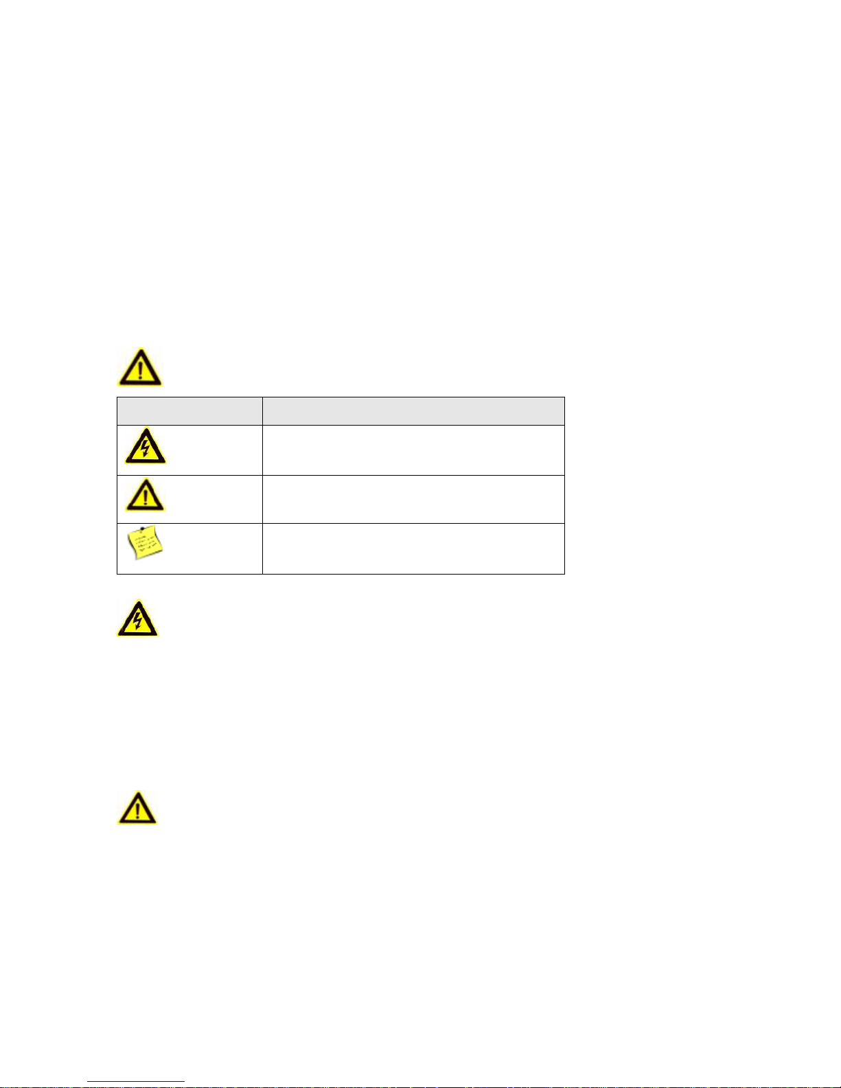
Preventive and Cautionary Tips
Signs
Description
Warning
Follow these safeguards to prevent serious
injury or death.
Note
Follow these precautions to prevent potential
injury or material damage.
Tips
The additional information as a complimentary
of the contents.
Before connecting and operating your device, please be advised of the following tips:
Ensure unit is installed in a well-ventilated, dust-free environment.
Keep all liquids away from the device.
Ensure environmental conditions meet factory specifications.
Ensure unit is properly secured to a rack or shelf. Major shocks or jolts to the unit as a result of
dropping it may cause damage to the sensitive electronics within the unit.
Use the device in conjunction with an UPS if possible.
Power down the unit before connecting and disconnecting accessories and peripherals.
A factory recommended HDD should be used for this device.
Improper use or replacement of the battery may result in hazard of explosion. Replace with the
same or equivalent type only. Dispose of used batteries according to the instructions provided
by the manufacturer.
Safety Information
Warnings
Please adopt the power adapter from the legitimate factory which can meet the safety extra low
voltage (SELV) standard.
Do not install, wiring, or uninstall when the power is still on.
To reduce the risk of fire or electrical shock, do not expose this product to rain or moisture.
This installation should be made by a qualified service person and should conform to all the local
codes.
If the product does not work properly, please contact your dealer or the nearest service center. Never
attempt to disassemble the product yourself. (We shall not assume any responsibility for problems
caused by unauthorized repair or maintenance.)
Note
Please do not drop the objects on hard surface, and keep the equipment from the magnetic field.
Avoid install the equipment to the vibrated or vulnerable places.
Please do not install the device in the extreme temperature (higher than 65°C or lower than -20°C)
Keep ventilation.
Do not operate in humid environment.
Do not operate in explosive environment.
Keep the device clean and dry.
Avoid bare electrical wire.
4

Content
CHAPTER 1 PRODUCT DESCRIPTION ....................................................................................... 6
1.1 OVERVIEW................................................................................................................ 6
1.2 PRODUCT FUNCTION ............................................................................................. 6
CHAPTER 2 APPEARANCE .......................................................................................................... 7
2.1 COMPONENT DESCRIPTION ............................................................................................... 7
CHAPTER 3 TERMINAL CONNECTION ....................................................................................... 9
3.1 TERMINALS DESCRIPTION ................................................................................................. 9
CHAPTER 4 CARD READER INSTALLATION ........................................................................... 12
4.1 EXTERNAL TERMINAL ....................................................................................................... 12
4.2 CARD READER INSTALLATION ......................................................................................... 13
4.2.1 The Connection of Wiegand Card Reader .................................................................. 13
4.2.2 RS485 Card Reader Connection ................................................................................. 14
4.3 INSTALLING E-LOCK ......................................................................................................... 15
4.3.1 Installation of Cathode Lock ........................................................................................ 15
4.3.2 Installation of Anode Lock ........................................................................................... 15
4.4 CONNECTING THE EXTERNAL ALARM DEVICE ............................................................. 16
4.5 DOOR BUTTON WIRING DIAGRAM ................................................................................... 16
4.6 THE CONNECTION OF MAGNETICS DETECTION ........................................................... 17
4.7 CONNECTING POWER SUPPLY ....................................................................................... 17
4.8 ARMING REGION INPUT TERMINAL ................................................................................. 18
4.8.1 Connecting Normally Open Detector ........................................................................... 18
4.8.2 Connecting Normally Closed Detector ........................................................................ 18
CHAPTER 5 SETTINGS ............................................................................................................... 19
5.1 INITIALIZING THE HARDWARE .......................................................................................... 19
5.2 RELAY INPUT NO/NC ......................................................................................................... 19
5.2.1 Lock Relay Output ....................................................................................................... 19
5.2.2 Alarm Relay Output Status .......................................................................................... 20
CHAPTER 6 ACTIVATING THE CONTROL PANEL................................................................... 22
6.1 ACTIVATION VIA SADP SOFTWARE ................................................................................. 22
6.2 ACTIVATION VIA CLIENT SOFTWARE .............................................................................. 24
SPECIFICATION ............................................................................................................................... 26
5

Chapter 1. Product Description
1.1 Overview
VS-AXESS-4DLX is a powerful and stable access controller, using the logical architecture design.
VS-AXESS-4DLX is designed with TCP/IP network interface and its signal processed with special
encryption and can be run offline. Anti-tampering function is also supported.
1.2 Product Function
The access controller is equipped with 32-bit high-speed processor;
Supports TCP/IP network communication, with self-adaptive network interface. The
communication data is specially encrypted to relieve the concern of privacy leak;
Support recognition and storage of card number with maximum length of 20;
The access controller can store 100 thousand legal cards and 300 thousand card swiping
records;
Supports multi-door interlock function, anti-passback function, multi-card function, first card
open function, super card and super password function, online upgrade function and remote
control of the doors;
Supports tamper-proof alarm for card reader, alarm for door not secured, force opening door
alarm, alarm for door opening timeout, duress card and code alarm, blacklist alarm and alarm
for illegal card swiping attempts reaching the limit.;
The alarm input of controller supports short circuit protection function and cut-proof function;
Supports RS485 interface and Wiegand interface for accessing card reader. RS485 interface
adopts dual-interface design and supports loop breakpoint detection and redundancy
function; Wiegand interface supports W26, W34 and is seamlessly compatible with third-party
card reader with Wiegand interface;
Supports various card types as normal/ disabled/ blacklist/ patrol/ guest/ duress/super card,
etc.;
Various indicators to show different status;
Supports time synchronization via NTP, manual or automatic method;
Supports record storage function when it is offline and insufficient storage space storage
alarm function;
The access controller has backup battery design, watchdog design and tamper-proof
function;
Data can be permanently saved after the access controller is powered off.
Supports I/O linkage, and event linkage;
Supports Ehome protocol, and inter-network communication.
500 groups of password under the authentication mode of card and password;
6
Chapter 2. Appearance
2.1 Component Description
Access Controller Component
Schematic Diagram
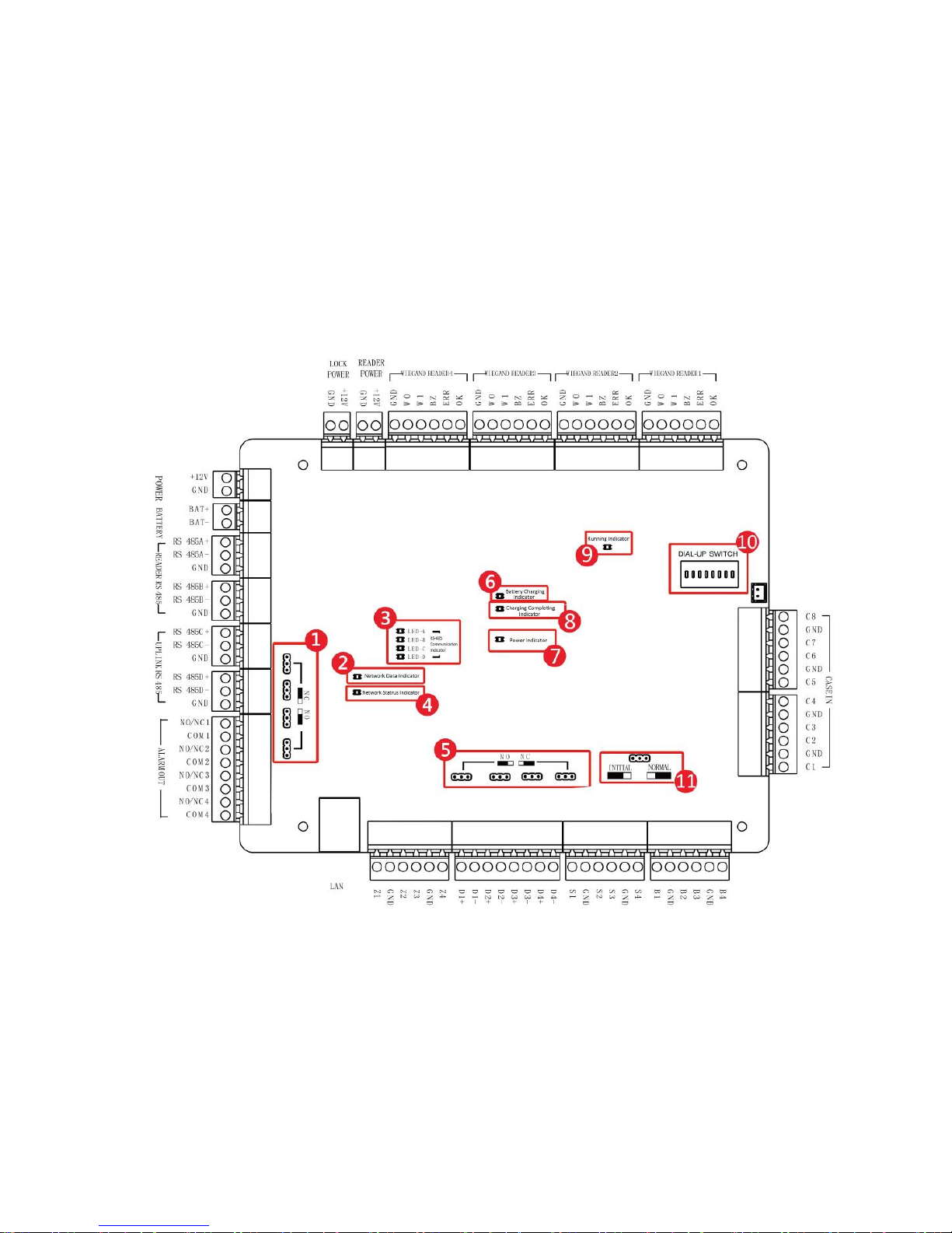
Take VS-AXESS-4DLX as an example, the component schematic diagram is shown below.
Figure 2-VS-AXESS-4DLX Component Schematic Diagram
7

No.
Component Description
VS-AXESS-4DLX
1
Alarm Relay Output Status (NC/NO)
2
Network Data Indicator
3
RS-485 Communication Indicator
4
Network Status Indicator
5
Door Relay Output Status (NC/NO) Choice
6
Battery Charging Indicator
7
Power Indicator
8
Charging Completing Indicator
9
Running Indicator
10
Hardware Initialization and Normal Working Choice
11
Main board dial-up switch/ Reserved
Table 2-1 VS-AXESS-4DLX Component Description
8
 Loading...