


Access Control Terminal·User Manual
One Door Network Access Control Panel
Controller Board with Cabinet TCP IP
Wiegand with Desktop Software and Power
Supply Included 10,000 Users
VS-AXESS-1ETL
VS-AXESS-1ETL-PCB
User Manual

Access Control Terminal·User Manual
User Manual
About This Manual
This Manual is applicable to access controller.
The Manual includes instructions for using and managing the product. Pictures, charts, images and all
other information hereinafter are for description and explanation only. The information contained in
the Manual is subject to change, without notice, due to firmware updates or other reasons. Please
find the latest version in the company website.
Please use this user manual under the guidance of professionals.
Legal Disclaimer
REGARDING TO THE PRODUCT WITH INTERNET ACCESS, THE USE OF PRODUCT SHALL BE WHOLLY AT
YOUR OWN RISKS. OUR COMPANY SHALL NOT TAKE ANY RESPONSIBILITES FOR ABNORMAL
OPERATION, PRIVACY LEAKAGE OR OTHER DAMAGES RESULTING FROM CYBER ATTACK, HACKER
ATTACK, VIRUS INSPECTION, OR OTHER INTERNET SECURITY RISKS; HOWEVER, OUR COMPANY WILL
PROVIDE TIMELY TECHNICAL SUPPORT IF REQUIRED.
SURVEILLANCE LAWS VARY BY JURISDICTION. PLEASE CHECK ALL RELEVANT LAWS IN YOUR
JURISDICTION BEFORE USING THIS PRODUCT IN ORDER TO ENSURE THAT YOUR USE CONFORMS THE
APPLICABLE LAW. OUR COMPANY SHALL NOT BE LIABLE IN THE EVENT THAT THIS PRODUCT IS USED
WITH ILLEGITIMATE PURPOSES.
IN THE EVENT OF ANY CONFLICTS BETWEEN THIS MANUAL AND THE APPLICABLE LAW, THE LATER
PREVAILS.

Access Control Terminal·User Manual
Regulatory Information
FCC Information
Please take attention that changes or modification not expressly approved by the party responsible for
compliance could void the user’s authority to operate the equipment.
FCC compliance: This equipment has been tested and found to comply with the limits for a Class B
digital device, pursuant to part 15 of the FCC Rules. These limits are designed to provide reasonable
protection against harmful interference in a residential installation. This equipment generates, uses
and can radiate radio frequency energy and, if not installed and used in accordance with the
instructions, may cause harmful interference to radio communications. However, there is no
guarantee that interference will not occur in a particular installation. If this equipment does cause
harmful interference to radio or television reception, which can be determined by turning the
equipment off and on, the user is encouraged to try to correct the interference by one or more of the
following measures:
—Reorient or relocate the receiving antenna.
—Increase the separation between the equipment and receiver.
—Connect the equipment into an outlet on a circuit different from that to which the receiver is
connected.
—Consult the dealer or an experienced radio/TV technician for help.
FCC Conditions
This device complies with part 15 of the FCC Rules. Operation is subject to the following two
conditions:
1. This device may not cause harmful interference.
2. This device must accept any interference received, including interference that may cause undesired
operation.
EU Conformity Statement
This product and - if applicable - the supplied accessories too are marked with "CE"
and comply therefore with the applicable harmonized European standards listed
under the EMC Directive 2004/108/EC, the RoHS Directive 2011/65/EU.
2012/19/EU (WEEE directive): Products marked with this symbol cannot be
disposed of as unsorted municipal waste in the European Union. For proper
recycling, return this product to your local supplier upon the purchase of equivalent
new equipment, or dispose of it at designated collection points. For more
information see: www.recyclethis.info.
2006/66/EC (battery directive): This product contains a battery that cannot be
disposed of as unsorted municipal waste in the European Union. See the product
documentation for specific battery information. The battery is marked with this
symbol, which may include lettering to indicate cadmium (Cd), lead (Pb), or
mercury (Hg). For proper recycling, return the battery to your supplier or to a
designated collection point. For more information see: www.recyclethis.info.
Industry Canada ICES-003 Compliance
This device meets the CAN ICES-3 (B)/NMB-3(B) standards requirements.
Preventive and Cautionary Tips
Before connecting and operating your device, please be advised of the following tips:
• Ensure unit is installed in a well-ventilated, dust-free environment.
• Keep all liquids away from the device.
• Ensure environmental conditions meet factory specifications.
• Ensure unit is properly secured to a rack or shelf. Major shocks or jolts to the unit as a result of
dropping it may cause damage to the sensitive electronics within the unit.
• Use the device in conjunction with an UPS if possible.
• Power down the unit before connecting and disconnecting accessories and peripherals.
• A factory recommended HDD should be used for this device.
i

Access Control Terminal·User Manual
• Improper use or replacement of the battery may result in hazard of explosion. Replace with the
same or equivalent type only. Dispose of used batteries according to the instructions provided by
the manufacturer.
ii
Warnings Follow
these safeguards
to prevent
serious injury or
death.
Cautions Follow these
precautions to
prevent potential
injury or material
damage.
Access Control Terminal·User Manual
Safety Instruction
These instructions are intended to ensure that user can use the product correctly to avoid danger or
property loss.
The precaution measure is divided into Warnings and Cautions:
Warnings: Neglecting any of the warnings may cause serious injury or death.
Cautions: Neglecting any of the cautions may cause injury or equipment damage.
Warnings
All the electronic operation should be strictly compliance with the electrical safety regulations, fire
prevention regulations and other related regulations in your local region.
Please use the power adapter, which is provided by normal company. The power consumption
cannot be less than the required value.
Do not connect several devices to one power adapter as adapter overload may cause over-heat or
fire hazard.
Please make sure that the power has been disconnected before you wire, install or dismantle the
device.
When the product is installed on wall or ceiling, the device shall be firmly fixed.
If smoke, odors or noise rise from the device, turn off the power at once and unplug the power
cable, and then please contact the service center.
If the product does not work properly, please contact your dealer or the nearest service center.
Never attempt to disassemble the device yourself. (We shall not assume any responsibility for
problems caused by unauthorized repair or maintenance.)
Cautions
Do not drop the device or subject it to physical shock, and do not expose it to high
electromagnetism radiation. Avoid the equipment installation on vibrations surface or places
subject to shock (ignorance can cause equipment damage).
Do not place the device in extremely hot (refer to the specification of the device for the detailed
operating temperature), cold, dusty or damp locations, and do not expose it to high electromagnetic
radiation. The appropriate operation temperature is 0℃ to +45℃, and the storage temperature
should be -10℃ to +55℃.
The device cover for indoor use shall be kept from rain and moisture.
Exposing the equipment to direct sun light, low ventilation or heat source such as heater or radiator
is forbidden (ignorance can cause fire danger).
Do not aim the device at the sun or extra bright places. A blooming or smear may occur otherwise
(which is not a malfunction however), and affecting the endurance of sensor at the same time.
Please use the provided glove when open up the device cover, avoid direct contact with the device
cover, because the acidic sweat of the fingers may erode the surface coating of the device cover.
Please use a soft and dry cloth when clean inside and outside surfaces of the device cover, do not
use alkaline detergents.
Please keep all wrappers after unpack them for future use. In case of any failure occurred, you need
to return the device to the factory with the original wrapper. Transportation without the original
wrapper may result in damage on the device and lead to additional costs.
iii

Access Control Terminal·User Manual
Improper use or replacement of the battery may result in hazard of explosion. Replace with the
same or equivalent type only. Dispose of used batteries according to the instructions provided by
the battery manufacturer.
iv

Access Control Terminal·User Manual
Table of Contents
Chapter 1 Product Description ......................................................................................................... 1
1.1 Overview .......................................................................................................................... 1
1.2 Main Features .................................................................................................................. 1
Chapter 1 Component Description .................................................................................................. 2
Chapter 2 Terminal Connection ........................................................................................................ 3
2.1 Terminal Description ........................................................................................................ 3
Chapter 3 External Device Wiring .................................................................................................... 5
3.1 Card Reader Wiring ......................................................................................................... 5
3.1.1 Wiegand Card Reader Wiring .................................................................................. 5
3.2 External Terminals ........................................................................................................... 6
3.2.3 Installation of Cathode Lock .................................................................................... 6
3.2.4 Installation of Anode Lock ....................................................................................... 6
3.3 Connecting the External Alarm Device ............................................................................ 7
3.4 Door Button Wiring Diagram ........................................................................................... 8
3.5 The Connection of Magnetics Detection ......................................................................... 8
3.6 Connecting Power Supply ................................................................................................ 9
Chapter 4 Settings .......................................................................................................................... 10
4.1 Initializing the Hardware ............................................................................................... 10
4.2 Relay Input NO/NC ........................................................................................................ 10
4.2.1 Lock Relay Output ................................................................................................. 10
4.2.2 Alarm Relay Output Status .................................................................................... 11
Chapter 5 Activating the Access Control Terminal ......................................................................... 13
5.1 Activating via SADP Software ........................................................................................ 13
5.2 Activating via Client Software ........................................................................................ 14
Chapter 6 Client Operation ............................................................................................................ 16
6.1 Function Modules .......................................................................................................... 16
6.2 User Registration and Login ........................................................................................... 19
6.3 System Configuration..................................................................................................... 21
6.4 Access Control Management ......................................................................................... 21
6.4.1 Adding Access Control Device ............................................................................... 22
6.4.2 Viewing Device Status ........................................................................................... 50
6.4.3 Editing Basic Information ...................................................................................... 51
6.4.4 Network Settings ................................................................................................... 52
6.4.5 Capture Settings .................................................................................................... 54
6.4.6 RS-485 Settings ...................................................................................................... 55
6.4.7 Wiegand Settings .................................................................................................. 56
6.4.8 M1 Card Encryption .............................................................................................. 57
6.4.9 Remote Configuration ........................................................................................... 57
6.5 Person and Card Management ...................................................................................... 65
6.5.1 Organization Management.................................................................................... 66
6.5.2 Person Management ............................................................................................. 67
6.6 Schedule and Template ................................................................................................. 75
6.6.1 Week Schedule ...................................................................................................... 76
6.6.2 Holiday Group ....................................................................................................... 77
6.6.3 Template ................................................................................................................ 78
6.7 Permission Configuration .............................................................................................. 80
6.7.1 Adding Permission ................................................................................................. 81
6.7.2 Applying Permission .............................................................................................. 82
6.8 Advanced Functions ...................................................................................................... 82
6.8.1 Access Control Parameters .................................................................................... 83
6.8.2 Card Reader Authentication .................................................................................. 86
6.8.3 Multiple Authentication ........................................................................................ 87
6.8.4 Open Door with First Card ..................................................................................... 90
6.8.5 Anti-Passing Back .................................................................................................. 91
6.8.6 Cross-Controller Anti-passing Back ....................................................................... 92
v

Access Control Terminal·User Manual
6.8.7 Multi-door Interlocking ......................................................................................... 95
6.8.8 Authentication Password ...................................................................................... 96
6.8.9 Custom Wiegand ................................................................................................... 97
6.9 Searching Access Control Event ..................................................................................... 99
6.10 Access Control Event Configuration ............................................................................. 100
6.10.1 Access Control Event Linkage .............................................................................. 100
6.10.2 Access Control Alarm Input Linkage .................................................................... 101
6.10.3 Event Card Linkage .............................................................................................. 102
6.10.4 Cross-Device Linkage ........................................................................................... 104
6.11 Door Status Management ........................................................................................... 106
6.11.1 Access Control Group Management ................................................................... 106
6.11.2 Anti-control the Access Control Point (Door) ...................................................... 107
6.11.3 Status Duration Configuration ............................................................................. 108
6.11.4 Real-time Card Swiping Record ........................................................................... 110
6.11.5 Real-time Access Control Alarm .......................................................................... 110
6.12 Arming Control ............................................................................................................ 111
Appendix 1 Sound Prompt and Indicator ............................................................................................. 113
Appendix 2 Custom Wiegand Rule Descriptions .................................................................................. 114
vi

Access Control Terminal·User Manual
Chapter 1 Product Description
1.1 Overview
VS-AXESS-1ETL is a powerful and stable access controller, using the logical architecture design.
VS-AXESS-1ETL is designed with TCP/IP network interface and its signal processed with special
encryption and can be run offline. Anti-tampering function is also supported.
1.2 Main Features
The access controller is equipped with 32-bit high-speed processor
Supports TCP/IP network communication, with self-adaptive network interface. The
communication data is specially encrypted to relieve the concern of privacy leak
Supports recognition and storage of card number with maximum length of 20
The access controller can store 10 thousand legal cards and 50 thousand card swiping records
Supports first card open-door and first card authorization function, super card and super
password function, online upgrade function and remote control of the doors
Supports Wiegand interface for accessing card reader. Wiegand interface supports W26/W34 and
is seamlessly compatible with third-party card reader with Wiegand interface
Supports various card types as normal/ disabled/ blacklist/ patrol/ guest/ duress/ super card, etc.
Supports time synchronization via NTP, manual or automatic method
Supports record storage function when it is offline and insufficient storage space storage alarm
function
The access controller has watchdog design
Data can be permanently saved after the access controller is powered off.
Supports I/O linkage, and event linkage
Supports alarm of offline event exceeding 90%
Multiple event upload methods: channel, center group, and listening
500 groups of authentication code
Anti-pass-back function.
1
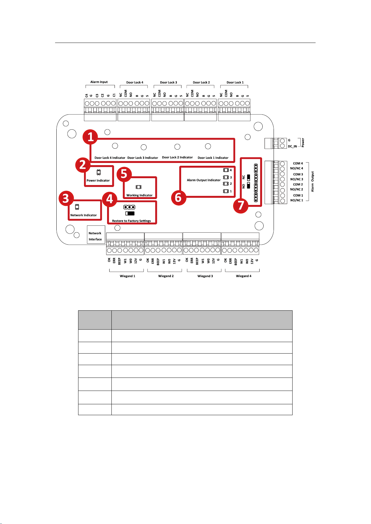
No.
Component Description
1
Door Lock 1 Indicator
2
Power Indicator
3
Network Indicator
4
Jumper Cap for Restoring Factory Settings
5
Working Indicator
6
Alarm Output Indicator
7
Alarm Output (NO/NC) Jumper Cap
Access Control Terminal·User Manual
Chapter 1 Component Description
Take VS-AXESS-4ETL as an example, the component schematic diagram is shown below.
VS-AXESS-1ETL component descriptions are as follows:
2
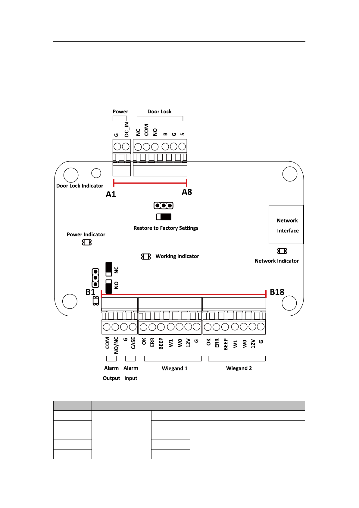
No.
VS-AXESS-1ETL
A1
Power
GND
DC12V Grounding
A2
+12V
DC12V Input
A3
Door
NC
Door Lock Relay Output
A4
COM
A5
NO
Access Control Terminal·User Manual
Chapter 2 Terminal Connection
2.1 Terminal Description
VS-AXESS-1ETL Terminal descriptions are as follows:
3

No.
VS-AXESS-1ETL
A6
BUTTON
Door Button Input
A7
GND
Grounding
A8
SENSOR
Door Magnetic detector
B1
Alarm Output
COM
Alarm Relay Output (Dry Contact)
B2
NO/NC
B3
Alarm Input
GND
Grounding
B4
IN
Event Input
B5
Wiegand Card
Reader 1
OK
Indicator of Card Reader Control Output
(Valid Card Output)
B6
ERR
Indicator of Card Reader Control Output
(Invalid Card Output)
B7
BZ
Card Reader Buzzer Control Output
B8
W1
Wiegand Head Read Data Input Data1
B9
W0
Wiegand Head Read Data Input Data0
B10
PWR
Card Reader Power Output
B11
GND
B12
Wiegand Card
Reader 2
OK
Indicator of Card Reader Control Output
(Valid Card Output)
B13
ERR
Indicator of Card Reader Control Output
(Invalid Card Output)
B14
BZ
Card Reader Buzzer Control Output
B15
W1
Wiegand Head Read Data Input Data1
B16
W0
Wiegand Head Read Data Input Data0
B17
PWR
Card Reader Power Output
B18
GND
Access Control Terminal·User Manual
Notes:
The Alarm input hardware interface is normally open by default. So only the normally open signal
is allowed. It can be linked to the buzzer of the card reader and access controller, and the alarm
relay output and open door relat output.
For single-door access controller, the Wiegand card reader 1 and 2 respectively correspond to the
entering and exiting card readers of door 1.
4
Black
Red
Green
White
Purple
Orange
Brown
Controller
Card Reader
Access Control Terminal·User Manual
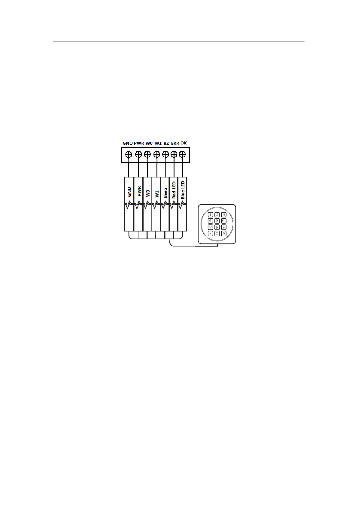
Chapter 3 External Device Wiring
3.1 Card Reader Wiring
3.1.1 Wiegand Card Reader Wiring
Note: You must connect the OK/ERR/BZ, if using access controller to control the LED and buzzer of the
Wiegand card reader.
5
Access Control Terminal·User Manual
3.2 VS-AXESS-1ETL External Terminals
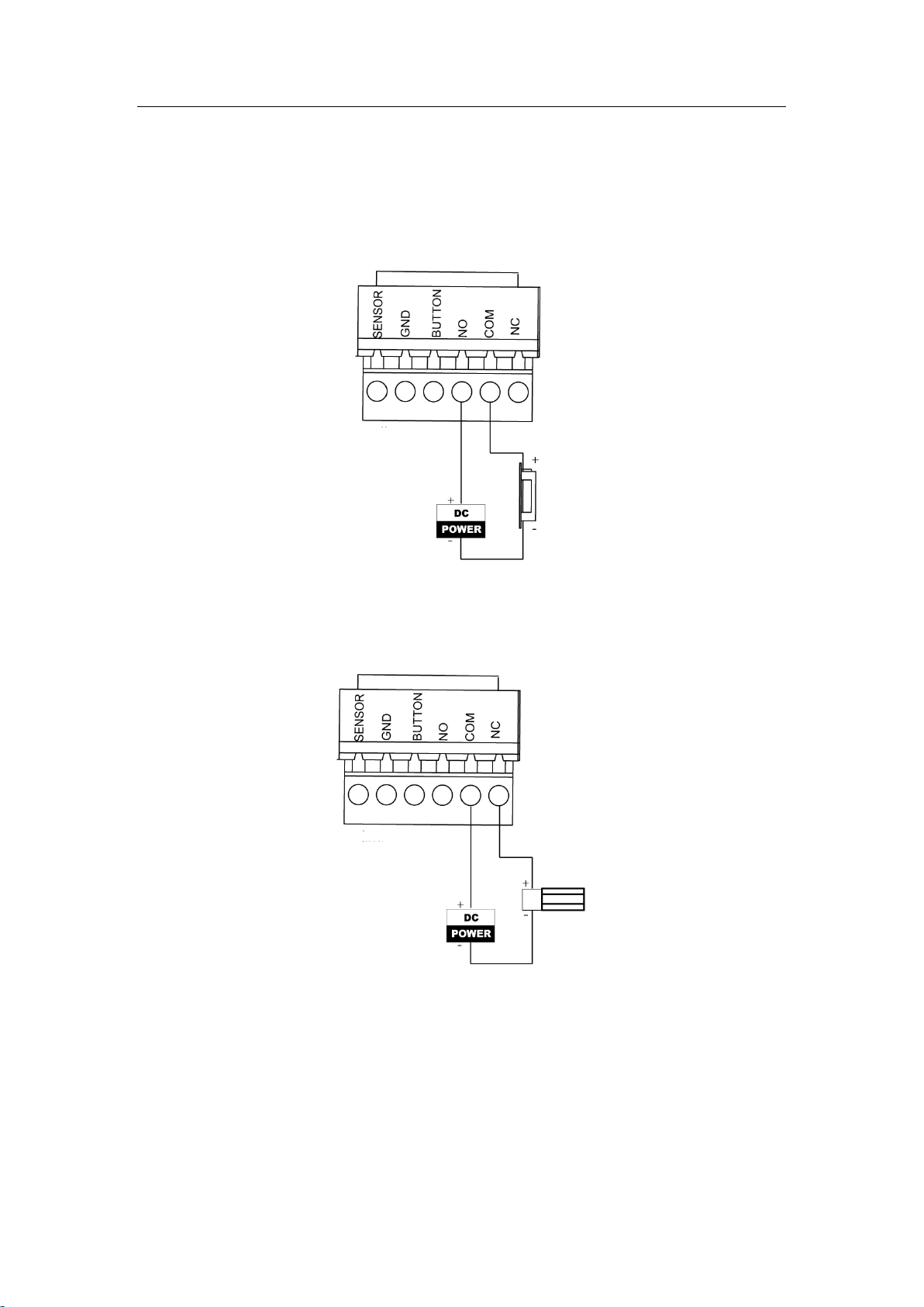
3.2.2 Installation of Cathode Lock
3.2.3 Installation of Anode Lock
6
Access Control Terminal·User Manual
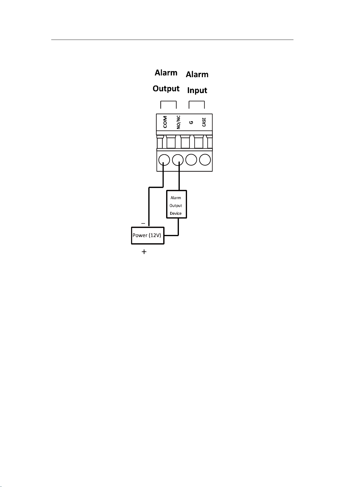
3.3 Connecting the External Alarm Device
7
Access Control Terminal·User Manual
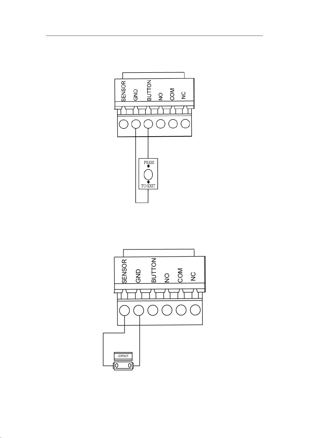
3.4 Door Button Wiring Diagram
3.5 The Connection of Magnetics Detection
8

Access Control Terminal·User Manual
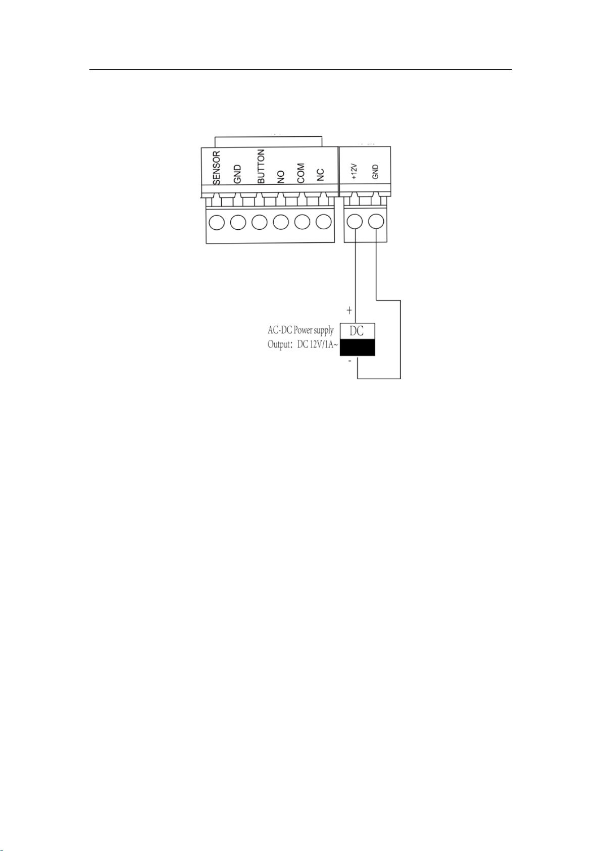
3.6 Connecting Power Supply
9
Access Control Terminal·User Manual
Chapter 4 Settings
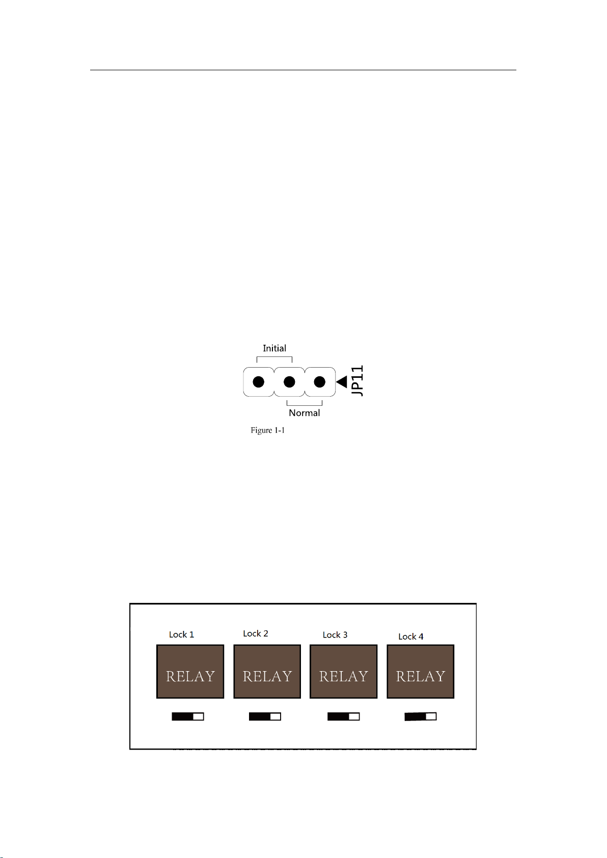
4.1 Initializing the Hardware
Option 1:
Steps:
1. Remove the jumper cap from the Normal terminal.
2. Disconnect the power and restart the access controller. The controller buzzer buzzes a long beep.
3. When the beep stopped, plug the jumper cap back to Normal.
Option 2:
Steps:
1. Jump the jumper cap from Normal to Initial.
2. Disconnect the power and restart the access controller. The controller buzzer buzzes a long
beep.
3. When the beep stopped, jump the jumper cap back to Normal.
Initialization Dial-up
Note: The initializing of the hardware will restore all the parameters to the default setting and all the
device events are wiping out.
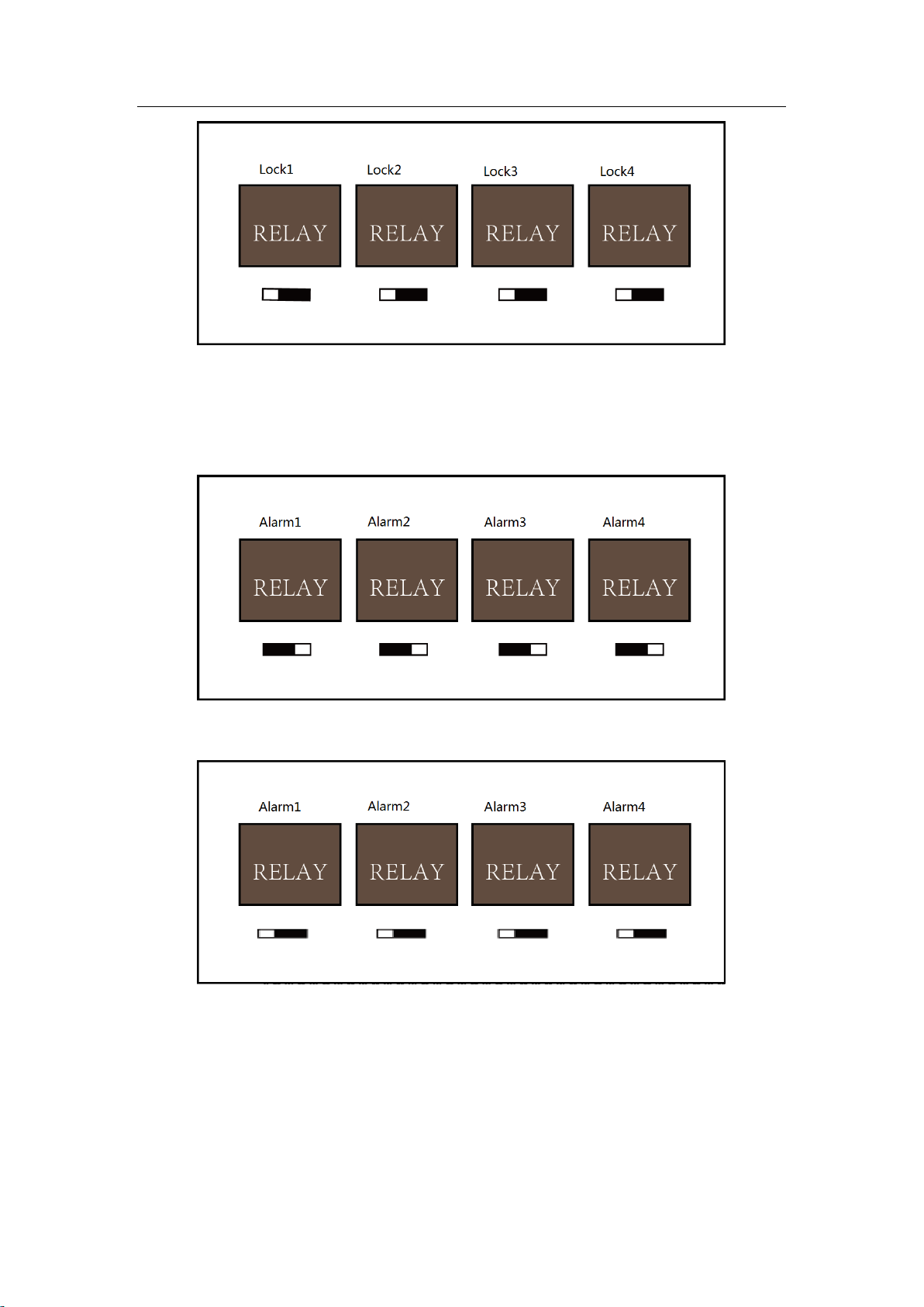
4.2 Relay Input NO/NC
4.2.1 Lock Relay Output
Lock Relay Normally Open Status:
Lock Relay Normally Closed Status:
10
Access Control Terminal·User Manual
4.2.2 Alarm Relay Output Status
Alarm Relay Output Normally Open:
Alarm Relay Output Normally Closed:
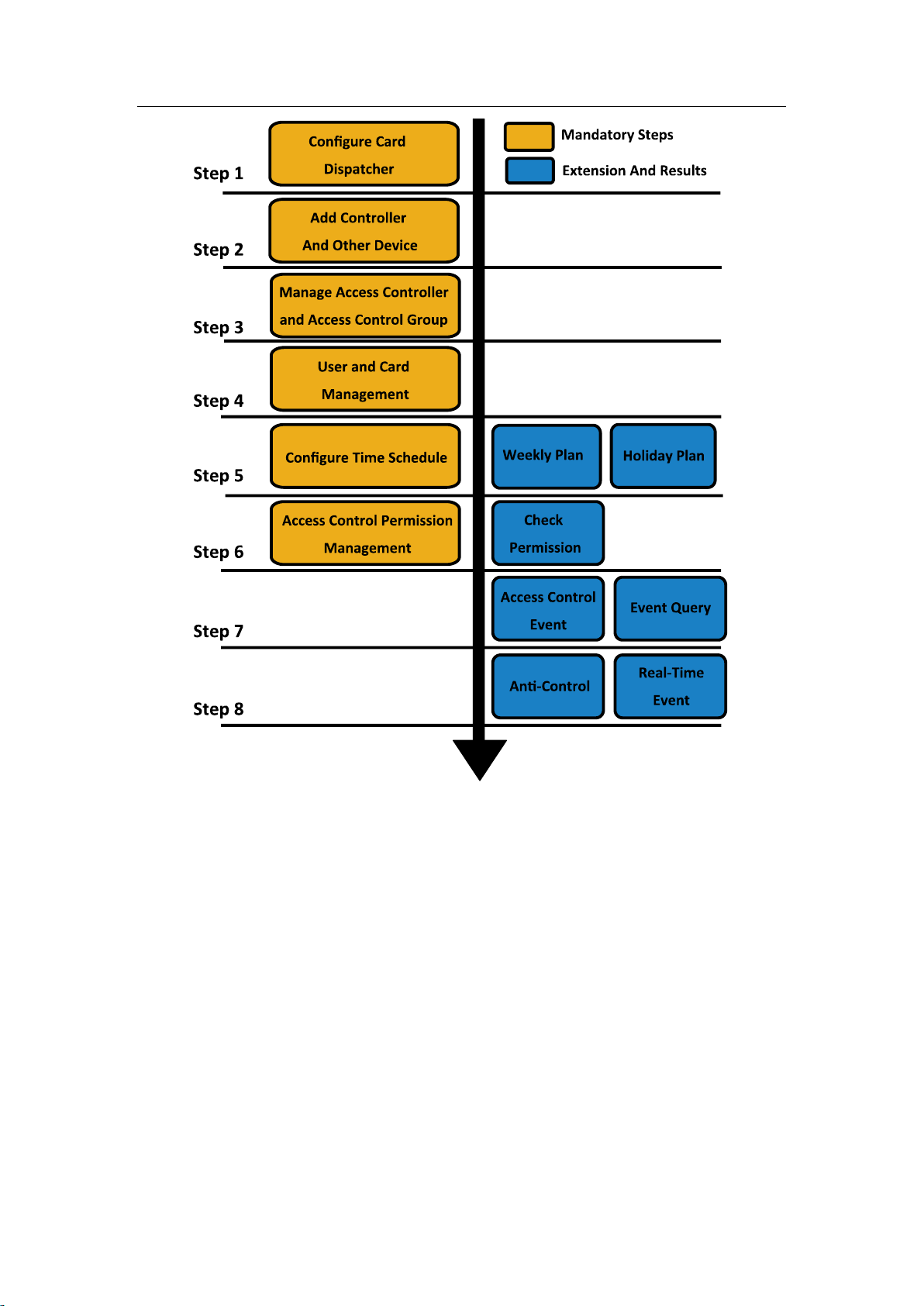
Work Flow of Software
For detailed information, please see the user manual of the client software.
Refer to the following work flow:
11
Access Control Terminal·User Manual
12
Access Control Terminal·User Manual
Chapter 5 Activating the Access
Control Terminal
Purpose:
You are required to activate the terminal first before using it.
Activation via SADP, and activation via client software are supported.
The default values of the control terminal are as follows.
The default IP address: 192.0.0.64.
The default port No.: 8000.
The default user name: admin.
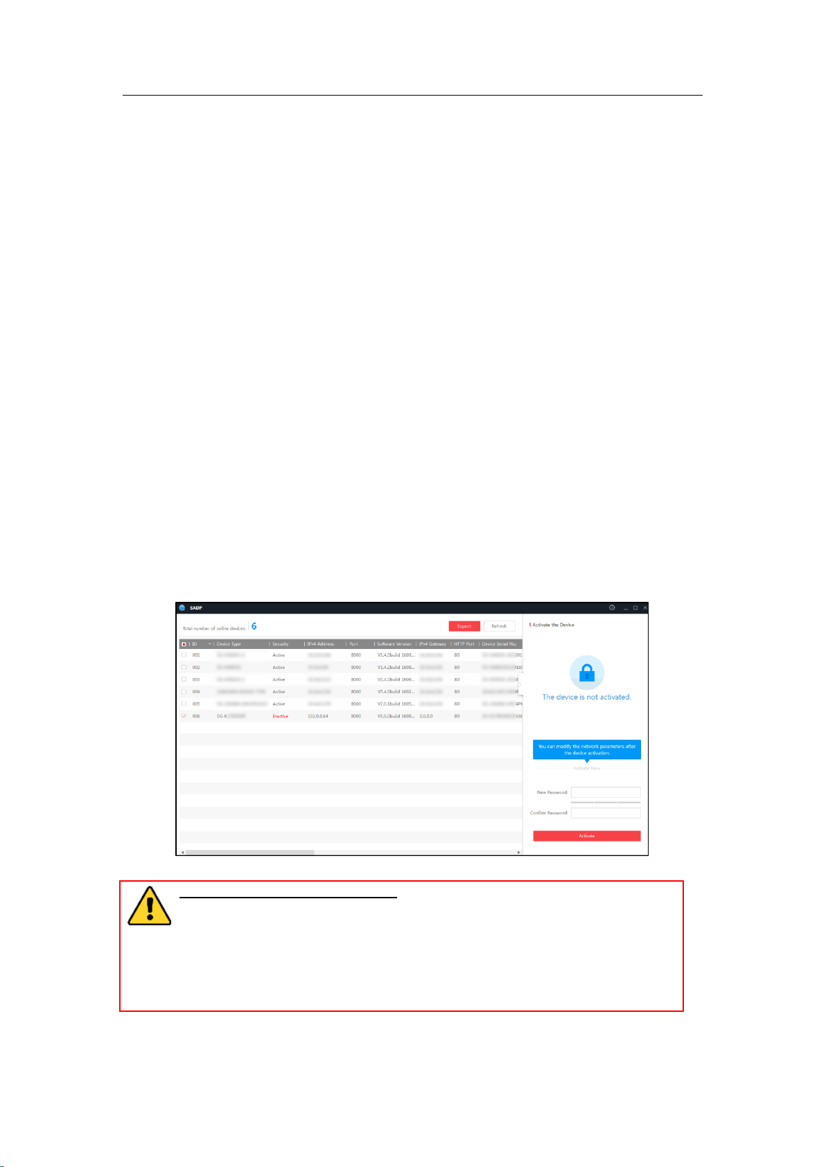
5.1 Activating via SADP Software
SADP software is used for detecting the online device, activating the device, and resetting the
password.
Get the SADP software from the supplied disk or the official website, and install the SADP according to
the prompts. Follow the steps to activate the control panel.
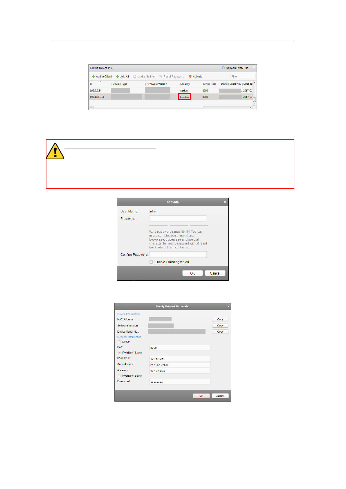
Steps:
1. Run the SADP software to search the online devices.
2. Check the device status from the device list, and select an inactive device.
3. Create a password and input the password in the password field, and confirm the password.
STRONG PASSWORD RECOMMENDED– We highly recommend you create a strong
password of your own choosing (using a minimum of 8 characters, including upper case
letters, lower case letters, numbers, and special characters) in order to increase the
security of your product. And we recommend you reset your password regularly,
especially in the high security system, resetting the password monthly or weekly can
better protect your product.
4. Click Activate to activate the device.
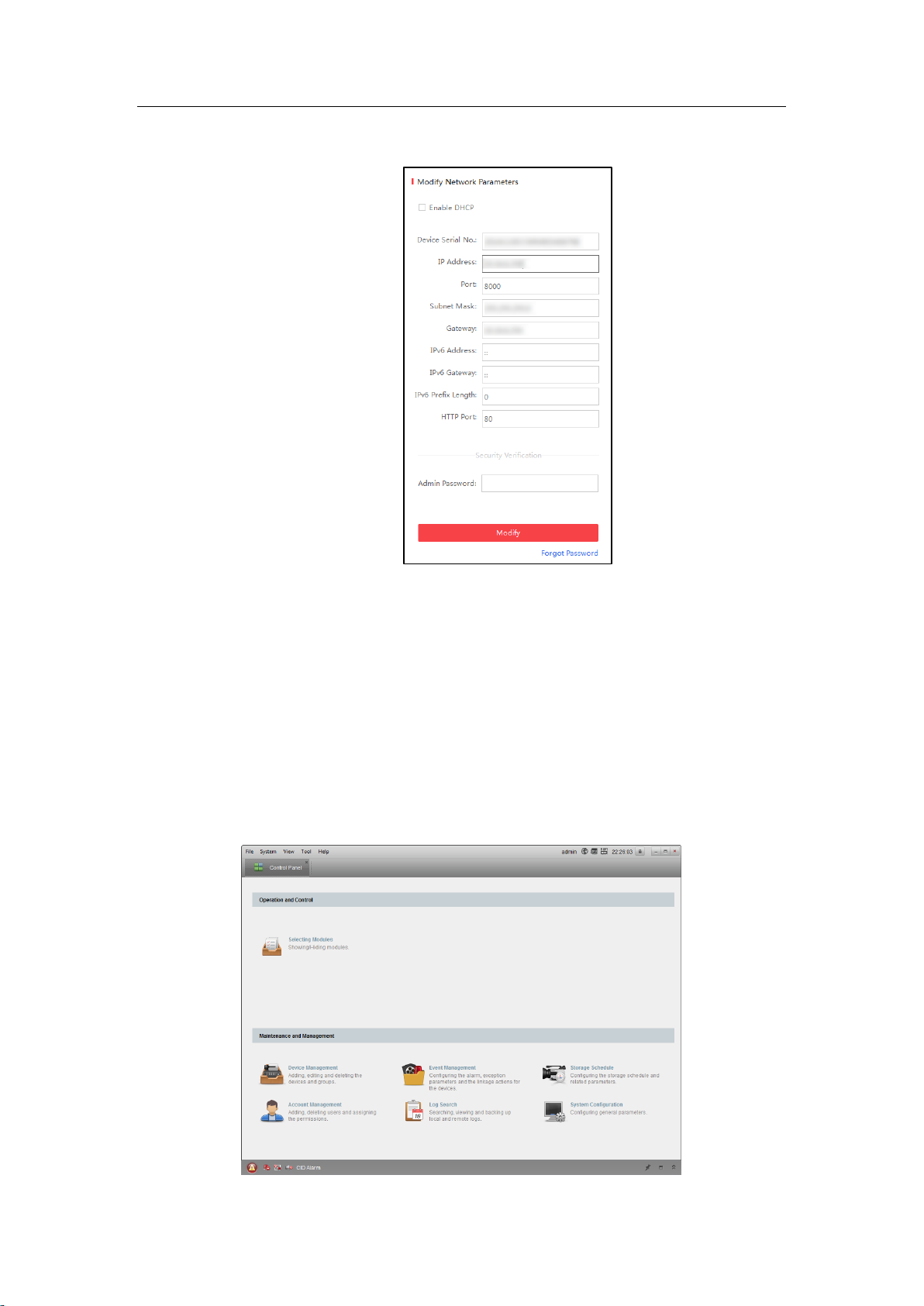
5. Check the activated device. You can change the device IP address to the same network segment
13
Access Control Terminal·User Manual
with your computer by either modifying the IP address manually or checking the checkbox of
Enable DHCP.
6. Input the password and click the Modify button to activate your IP address modification.
5.2 Activating via Client Software
The client software is versatile video management software for multiple kinds of devices.
Get the client software from the supplied disk or the official website, and install the software
according to the prompts. Follow the steps to activate the control panel.
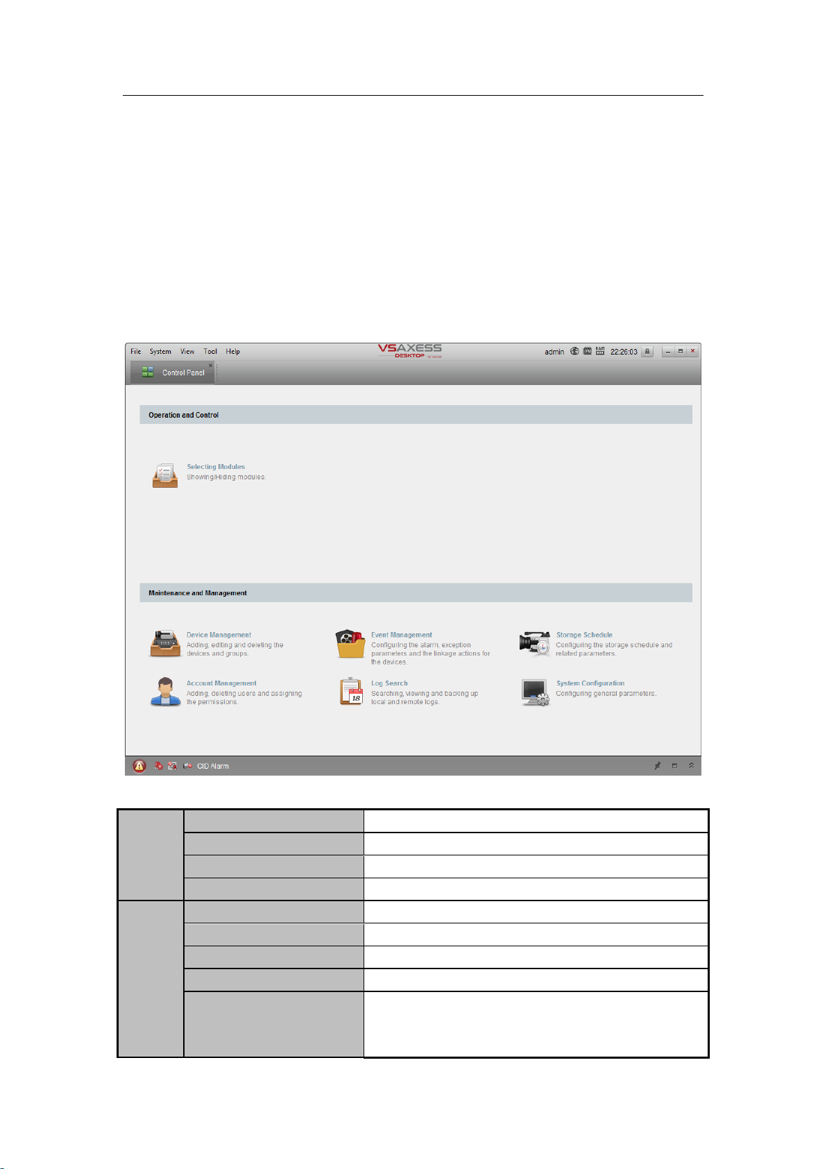
Steps:
1. Run the client software and the control panel of the software pops up, as shown in the figure
below.
14
Access Control Terminal·User Manual
2. Click the Device Management to enter the Device Management interface.
3. Check the device status from the device list, and select an inactive device.
4. Click the Activate button to pop up the Activation interface.
5. In the pop-up window, create a password in the password field, and confirm the password.
STRONG PASSWORD RECOMMENDED– We highly recommend you create a strong password
of your own choosing (using a minimum of 8 characters, including upper case letters, lower
case letters, numbers, and special characters) in order to increase the security of your product.
And we recommend you reset your password regularly, especially in the high security system,
resetting the password monthly or weekly can better protect your product.
6. Click OK button to activate
7. Click the Modify Netinfor button to pop up the Network Parameter Modification interface.
8. Change the device IP address to the same network segment with your computer by either
modifying the IP address manually.
9. Input the password and click the OK button to save the settings.
15
File
Open Image File
Search and view the captured pictures stored on local PC.
Open Video File
Search and view the video files recorded on local PC.
Open Log File
View the backup log files.
Exit
Exit the VSAXESS client software.
System
Lock
Lock screen operations. Log in the client again to unlock.
Switch User
Switch the login user.
Import System Config File
Import client configuration file from your computer.
Export System Config File
Export client configuration file to your computer.
Auto Backup
Set the schedule for backing up the database including
person, attendance data, and permission data
automatically.
Access Control Terminal·User Manual
Chapter 6 Client Operation
You can set and operate the access control devices via the client software. This chapter will introduce
the access control device related operations in the client software. For integrated operations, refer to
User Manual of VSAXESS Client Software.
6.1 Function Modules
Control Panel of VSAXESS:
Menu Bar:
16

View
1024*768
Display the window at size of 1024*768 pixels.
1280*1024
Display the window at size of 1280*1024 pixels.
1440*900
Display the window at size of 1440*900 pixels.
1680*1050
Display the window at size of 1680*1050 pixels.
Maximize
Display the window in maximum mode.
Control Panel
Enter Control Panel interface.
Main View
Open Main View page.
Remote Playback
Open Remote Playback page.
Access Control
Enter the Access Control Module.
Status Monitor
Enter the Status Monitor Module.
Time and Attendance
Enter the Time and Attendance Module.
Security Control Panel
Enter the Security Control Panel Module.
Real-time Alarm
Enter the Real-time Alarm Module.
Video Wall
Open Video Wall page.
E-map
Open E-map page.
Auxiliary Screen Preview
Open Auxiliary Screen Preview window.
Tool
Device Management
Open the Device Management page.
Event Management
Open the Event Management page.
Storage Schedule
Open the Storage Schedule page.
Account Management
Open the Account Management page.
Log Search
Open the Log Search page.
System Configuration
Open the System Configuration page.
Broadcast
Select camera to start broadcasting.
Device Arming Control
Set the arming status of devices.
Alarm Output Control
Turn on/off the alarm output.
Batch Wiper Control
Batch starting or stopping the wipers of the devices.
Batch Time Sync
Batch time synchronization of the devices.
Player
Open the player to play the video files.
Message Queue
Display the information of Email message to be sent.
Help
Open Video Wizard
Open the video guide for the video surveillance
configuration.
Open Video Wall Wizard
Open the guide for the video wall configuration.
Open Security Control Panel
Wizard
Open the guide for the security control panel
configuration.
Open Access Control and
Video Intercom Wizard
Open the guide for the access control and video intercom
configuration.
Open Attendance Wizard
Open the guide for the time and attendance
configuration.
User Manual (F1)
Click to open the User Manual; you can also open the User
Manual by pressing F1 on your keyboard.
About
View the basic information of the client software.
Language
Select the language for the client software and reboot the
Access Control Terminal·User Manual
17
software to activate the settings.
The Main View module provides live view of network cameras and video encoders, and
supports some basic operations, such as picture capturing, recording, PTZ control, etc.
The Remote Playback module provides the search, playback, export of video files.
The Access Control module provides managing the organizations, persons, permissions,
and advanced access control functions.
Provides video intercom function.
The Status Monitor module provides monitoring and controlling the door status, viewing
the real-time card swiping records and access control events.
The Time and Attendance module provides setting the attendance rule for the employees
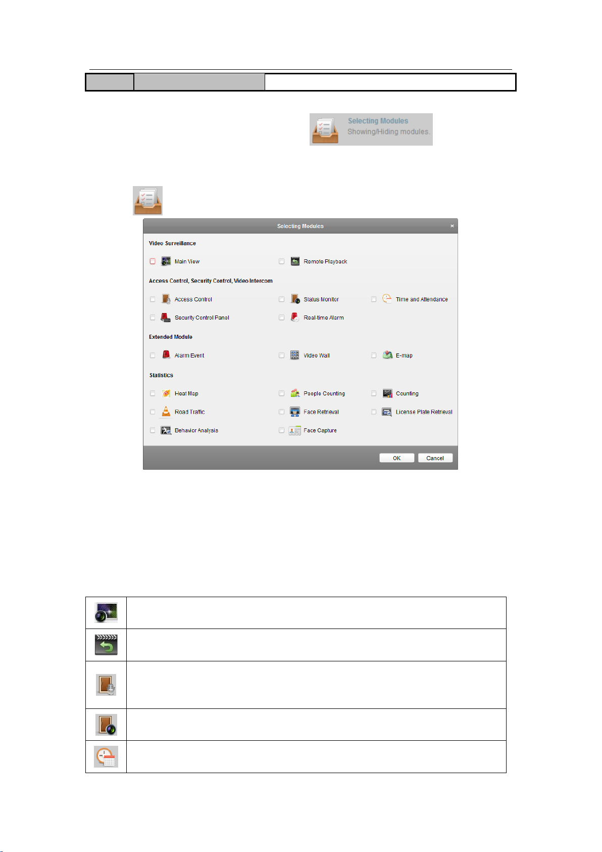
and generating the reports.
Access Control Terminal·User Manual
For the first time running the software, you can click on the control
panel to select the modules to display on the Operation and Control area of the control pane.
Steps:
1. Click to pop up the following dialog.
2. Check the module checkboxes to display them on the control panel according to the actual needs.
3. Click OK to save the settings.
Notes:
After adding the access control device in Device Management module, the Access Control, Status,
and Time and Attendance module will be displayed on the control panel automatically.
After adding the security control panel in Device Management module, the Security Control
Panel and Real-time Alarm modules will be displayed on the control panel automatically.
The VSAXESS client software is composed of the following function modules:
18
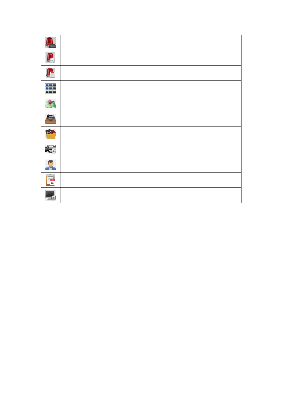
The Security Control Panel module provides operations such as arming, disarming,
bypass, group bypass, and so on for both the partitions and zones.
The Real-time Alarm module provides displaying the real-time alarm of security control
panel, acknowledging alarms, and searching the history alarms.
The Alarm Event module displays the alarm and event received by the client software.
The Video Wall module provides the management of decoding device and video wall and
the function of displaying the decoded video on video wall.
The E-map module provides the displaying and management of E-maps, alarm inputs, hot
regions and hot spots.
The Device Management module provides the adding, modifying and deleting of different
devices and the devices can be imported into groups for management.
The Event Management module provides the settings of arming schedule, alarm linkage
actions and other parameters for different events.
The Storage Schedule module provides the schedule settings for recording and pictures.
The Account Management module provides the adding, modifying and deleting of user
accounts and different permissions can be assigned for different users.
The Log Search module provides the query of system log files and the log files can be
filtered by different types.
The System Configuration module provides the configuration of general parameters, file
saving paths, alarm sounds and other system settings.
Access Control Terminal·User Manual
The function modules are easily accessed by clicking the navigation buttons on the control panel or by
selecting the function module from the View or Tool menu.
You can check the information, including current user, network usage, CPU usage, memory usage and
time, in the upper-right corner of the main page.
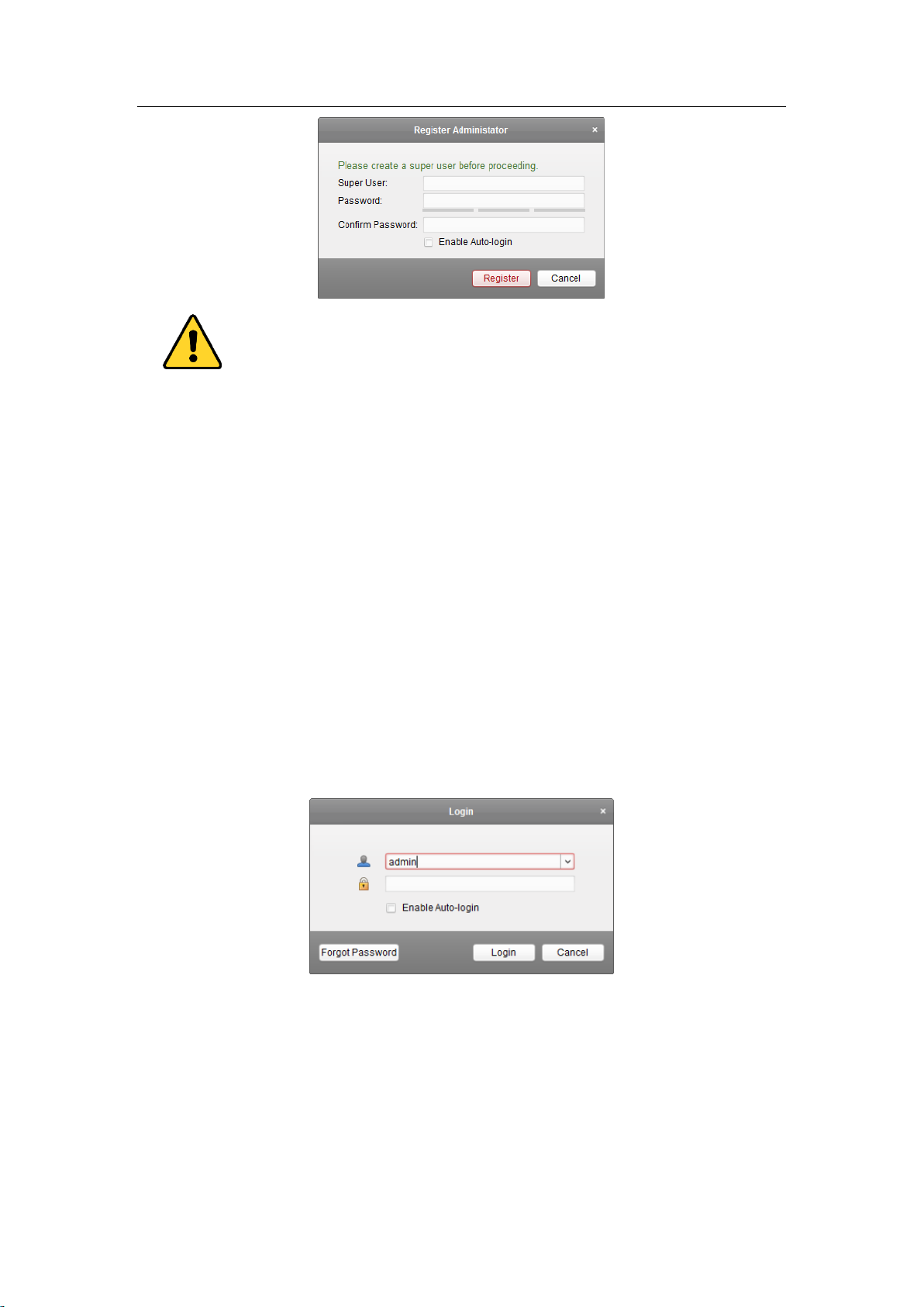
6.2 User Registration and Login
For the first time to use VSAXESS client software, you need to register a super user for login.
Steps:
1. Input the super user name and password. The software will judge password strength
automatically, and we highly recommend you to use a strong password to ensure your data
security.
2. Confirm the password.
3. Optionally, check the checkbox Enable Auto-login to log into the software automatically.
4. Click Register. Then, you can log into the software as the super user.
19
Access Control Terminal·User Manual
A user name cannot contain any of the following characters: / \ : * ? “ < > |. And the length of
the password cannot be less than 6 characters.
For your privacy, we strongly recommend changing the password to something of your own
choosing (using a minimum of 8 characters, including upper case letters, lower case letters,
numbers, and special characters) in order to increase the security of your product.
Proper configuration of all passwords and other security settings is the responsibility of the
installer and/or end-user.
When opening VSAXESS after registration, you can log into the client software with the registered user
name and password.
Steps:
1. Input the user name and password you registered.
Note: If you forget your password, please click Forgot Password and remember the encrypted
string in the pop-up window. Contact your dealer and send the encrypted string to him to reset
your password.
2. Optionally, check the checkbox Enable Auto-login to log into the software automatically.
3. Click Login.
After running the client software, you can open the wizards (including video wizard, video wall wizard,
security control panel wizard, access control and video intercom wizard, and attendance wizard), to
guide you to add the device and do other settings and operations. For detailed configuration about
the wizards, please refer to the Quick Start Guide of VSAXESS.
20
Access Control Terminal·User Manual
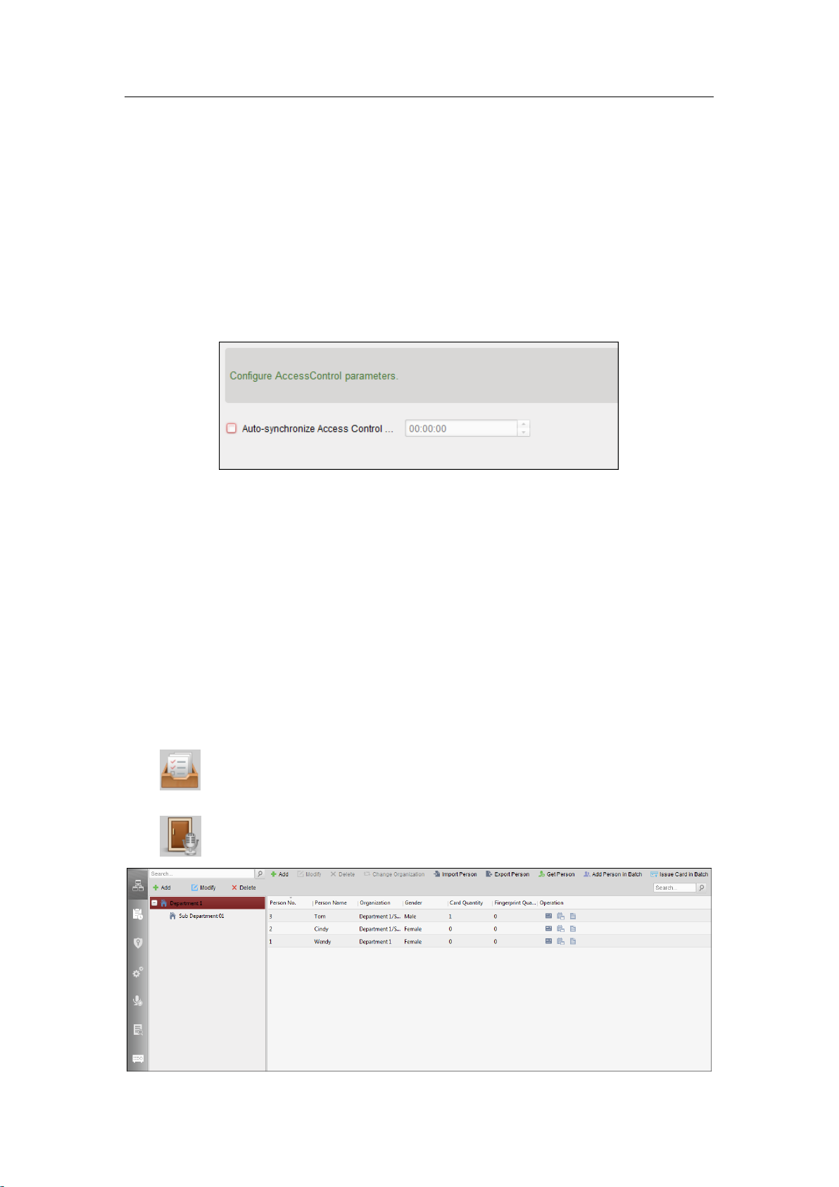
6.3 System Configuration
Purpose:
You can synchronize the missed access control events to the client.
Steps:
1. Click Tool – System Configuration.
2. In the System Configuration window, check the Auto-synchronize Access Control Event
checkbox.
3. Set the synchronization time.
The client will auto-synchronize the missed access control event to the client at the set time.
6.4 Access Control Management
Purpose:
The Access Control module is applicable to access control devices and video intercom. It provides
multiple functionalities, including person and card management, permission configuration, access
control status management, video intercom, and other advanced functions.
You can also set the event configuration for access control and display access control points and zones
on E-map.
Note: For the user with access control module permissions, the user can enter the Access Control
module and configure the access control settings. For setting the user permission of Access Control
module, refer to User Manual of VSAXESS Client Software.
Click in the control panel, and check Access Control to add the Access Control module to the
control panel.
Click to enter the Access Control module.
21
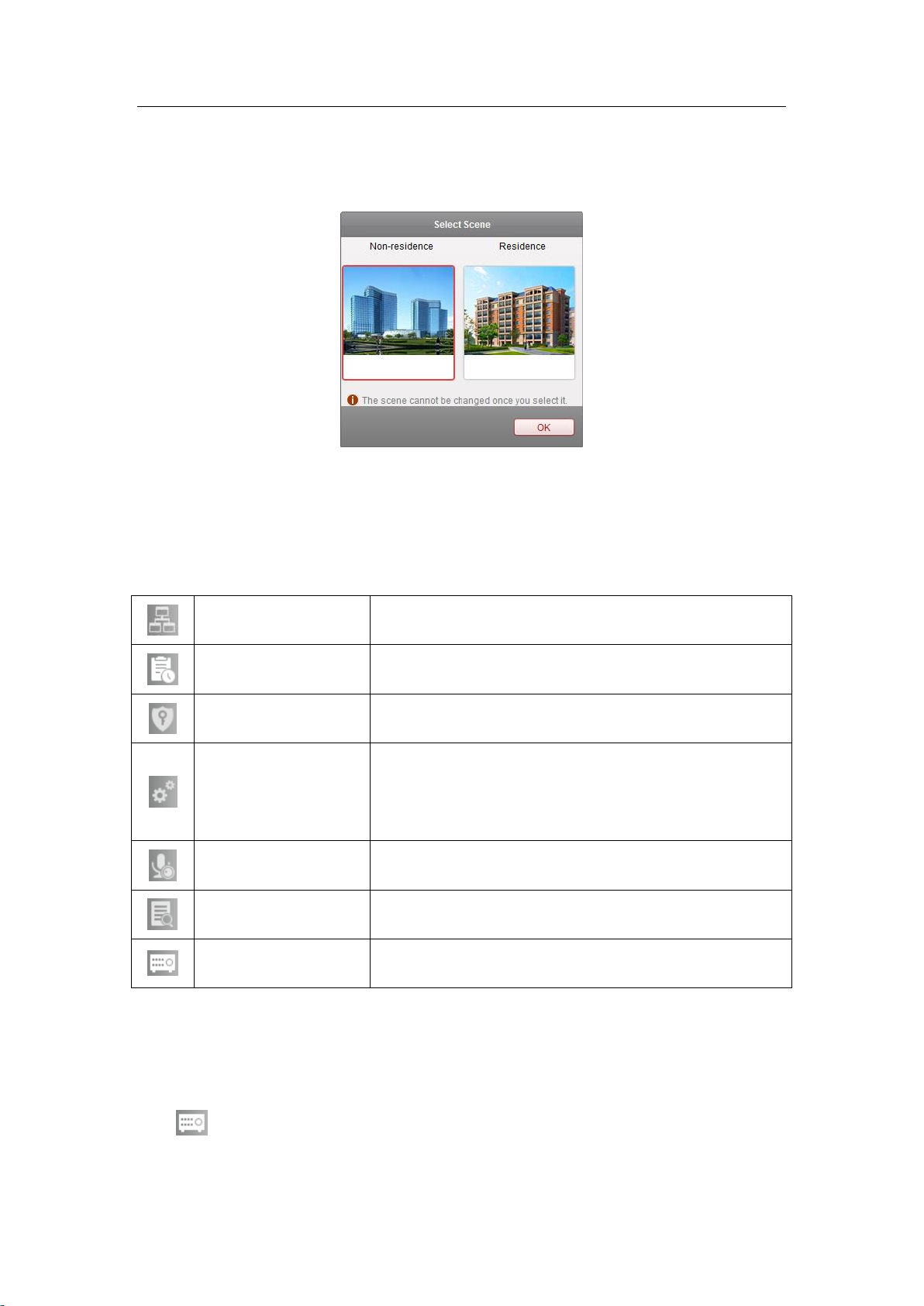
Person and Card
Managing the organizations, persons, and assigning cards to
persons.
Schedule and Template
Configuring the week schedule, holiday group, and setting the
template.
Permission
Assigning access control permissions to persons and applying to
the devices.
Advanced Function
Providing advanced functions including access control
parameters settings, card reader authentication, opening door
with first card, anti-passing back, multi-door interlocking, and
authentication password.
Video Intercom
Video intercom between client and resident, searching the dial
log, and releasing notice.
Search
Searching history events of access control; Searching call logs,
unlocking logs, and released notices.
Device Management
Managing the access control devices and video intercom
devices.
Access Control Terminal·User Manual
Before you start:
For the first time opening the Access Control module, the following dialog will pop up and you are
required to select the scene according to the actual needs.
You can select the scene as Non-residence and Residence.
Notes:
Once the scene is configured, you cannot change it later.
When you select Non-Residence mode, you cannot configure the Attendance Rule when adding
person.
The Access Control module is composed of the following sub modules.
Note: In this chapter, we only introduce the operations about access control.
6.4.1 Adding Access Control Device
Click in the Access Control module to enter the following interface.
22

Access Control Terminal·User Manual
Note: After adding the device, you should check the device arming status in Tool – Device Arming
Control. If the device is not armed, you should arm it, or you will not receive the real-time events via
the client software. For details about device arming control, refer 9.10 Arming Control.
Creating Password
Purpose:
For some devices, you are required to create the password to activate them before they can be added
to the software and work properly.
Note: This function should be supported by the device.
Steps:
1. Enter the Device Management page.
2. On the Device for Management or Online Device area, check the device status (shown on
Security column) and select an inactive device.
3. Click the Activate button to pop up the Activation interface.
4. Create a password in the password field, and confirm the password.
STRONG PASSWORD RECOMMENDED– We highly recommend you create a strong password of
your own choosing (using a minimum of 8 characters, including upper case letters, lower case
letters, numbers, and special characters) in order to increase the security of your product. And we
recommend you reset your password regularly, especially in the high security system, resetting
the password monthly or weekly can better protect your product.
23

Access Control Terminal·User Manual
5. (Optional) Enable Guarding Vision service when activating the device if the device supports.
1) Check Enable Guarding Vision checkbox to pop up the Note dialog.
2) Create a verification code.
3) Confirm the verification code.
4) Click Terms of Service and Privacy Policy to read the requirements.
5) Click OK to enable the Guarding Vision service.
6. Click OK to activate the device.
A “The device is activated.” window pops up when the password is set successfully.
7. Click Modify Netinfo to pop up the Modify Network Parameter interface.
Note: This function is only available on the Online Device area. You can change the device IP
address to the same subnet with your computer if you need to add the device to the software.
8. Change the device IP address to the same subnet with your computer by either modifying the IP
address manually or checking the checkbox of DHCP.
9. Input the password set in step 4 and click OK to complete the network settings.
24

Access Control Terminal·User Manual
Adding Online Device
Purpose:
The active online devices in the same local subnet with the client software will be displayed on the
Online Device area. You can click the Refresh Every 60s button to refresh the information of the
online devices.
Note: You can click to hide the Online Device area.
Steps:
1. Select the devices to be added from the list.
Note: For the inactive device, you need to create the password for it before you can add the
device properly. For detailed steps, please refer to Chapter 1 Product Description
Overview
VS-AXESS-1ETL is a powerful and stable access controller, using the logical architecture
design. VS-AXESS-1ETL is designed with TCP/IP network interface and its signal processed with
special encryption and can be run offline. Anti-tampering function is also supported.
6.5 Main Features
The access controller is equipped with 32-bit high-speed processor
Supports TCP/IP network communication, with self-adaptive network interface. The
communication data is specially encrypted to relieve the concern of privacy leak
Supports recognition and storage of card number with maximum length of 20
25

Access Control Terminal·User Manual
The access controller can store 10 thousand legal cards and 50 thousand card swiping records
Supports first card open-door and first card authorization function, super card and super
password function, online upgrade function and remote control of the doors
Supports Wiegand interface for accessing card reader. Wiegand interface supports W26/W34 and
is seamlessly compatible with third-party card reader with Wiegand interface
Supports various card types as normal/ disabled/ blacklist/ patrol/ guest/ duress/ super card, etc.
Supports time synchronization via NTP, manual or automatic method
Supports record storage function when it is offline and insufficient storage space storage alarm
function
The access controller has watchdog design
Data can be permanently saved after the access controller is powered off.
Supports I/O linkage, and event linkage
Supports alarm of offline event exceeding 90%
Multiple event upload methods: channel, center group, and listening
500 groups of authentication code
Anti-pass-back function.
26

No.
Component Description
1
Door Lock 1 Indicator
2
Power Indicator
3
Network Indicator
4
Jumper Cap for Restoring Factory Settings
5
Working Indicator
6
Alarm Output Indicator
7
Alarm Output (NO/NC) Jumper Cap
Access Control Terminal·User Manual
Chapter 2 Component Description
Take VS-AXESS-4ETL as an example, the component schematic diagram is shown below.
VS-AXESS-1ETL component descriptions are as follows:
27

No.
VS-AXESS-1ETL
A1
Power
GND
DC12V Grounding
A2
+12V
DC12V Input
A3
Door
NC
Door Lock Relay Output
A4
COM
A5
NO
Access Control Terminal·User Manual
Chapter 7 Terminal Connection
7.1 Terminal Description
VS-AXESS-1ETL Terminal descriptions are as follows:
28

No.
VS-AXESS-1ETL
A6
BUTTON
Door Button Input
A7
GND
Grounding
A8
SENSOR
Door Magnetic detector
B1
Alarm Output
COM
Alarm Relay Output (Dry Contact)
B2
NO/NC
B3
Alarm Input
GND
Grounding
B4
IN
Event Input
B5
Wiegand Card
Reader 1
OK
Indicator of Card Reader Control Output
(Valid Card Output)
B6
ERR
Indicator of Card Reader Control Output
(Invalid Card Output)
B7
BZ
Card Reader Buzzer Control Output
B8
W1
Wiegand Head Read Data Input Data1
B9
W0
Wiegand Head Read Data Input Data0
B10
PWR
Card Reader Power Output
B11
GND
B12
Wiegand Card
Reader 2
OK
Indicator of Card Reader Control Output
(Valid Card Output)
B13
ERR
Indicator of Card Reader Control Output
(Invalid Card Output)
B14
BZ
Card Reader Buzzer Control Output
B15
W1
Wiegand Head Read Data Input Data1
B16
W0
Wiegand Head Read Data Input Data0
B17
PWR
Card Reader Power Output
B18
GND
Access Control Terminal·User Manual
Notes:
The Alarm input hardware interface is normally open by default. So only the normally open signal
is allowed. It can be linked to the buzzer of the card reader and access controller, and the alarm
relay output and open door relat output.
For single-door access controller, the Wiegand card reader 1 and 2 respectively correspond to the
entering and exiting card readers of door 1.
29

Black
Red
Green
White
Purple
Orange
Brown
Controller
Card Reader
Access Control Terminal·User Manual
Chapter 8 External Device Wiring
8.1 Card Reader Wiring
8.1.1 Wiegand Card Reader Wiring
Note: You must connect the OK/ERR/BZ, if using access controller to control the LED and buzzer of the
Wiegand card reader.
30

Access Control Terminal·User Manual
8.2 VS-AXESS-1ETL External Terminals
8.2.2 Installation of Cathode Lock
8.2.3 Installation of Anode Lock
31

Access Control Terminal·User Manual
8.3 Connecting the External Alarm Device
32

Access Control Terminal·User Manual
8.4 Door Button Wiring Diagram
8.5 The Connection of Magnetics Detection
33
Access Control Terminal·User Manual
8.6 Connecting Power Supply
34

Access Control Terminal·User Manual
Chapter 9 Settings
9.1 Initializing the Hardware
Option 1:
Steps:
4. Remove the jumper cap from the Normal terminal.
5. Disconnect the power and restart the access controller. The controller buzzer buzzes a long beep.
6. When the beep stopped, plug the jumper cap back to Normal.
Option 2:
Steps:
4. Jump the jumper cap from Normal to Initial.
5. Disconnect the power and restart the access controller. The controller buzzer buzzes a long
beep.
6. When the beep stopped, jump the jumper cap back to Normal.
Initialization Dial-up
Note: The initializing of the hardware will restore all the parameters to the default setting and all the
device events are wiping out.
9.2 Relay Input NO/NC
9.2.1 Lock Relay Output
Lock Relay Normally Open Status:
Lock Relay Normally Closed Status:
35

Access Control Terminal·User Manual
9.2.2 Alarm Relay Output Status
Alarm Relay Output Normally Open:
Alarm Relay Output Normally Closed:
Work Flow of Software
For detailed information, please see the user manual of the client software.
Refer to the following work flow:
36

Access Control Terminal·User Manual
37

Access Control Terminal·User Manual
Activating the Access Control Terminal.
2. Click Add to Client to open the device adding dialog box.
3. Input the required information.
Nickname: Edit a name for the device as you want.
Address: Input the device’s IP address. The IP address of the device is obtained automatically in
this adding mode.
Port: Input the device port No.. The default value is 8000.
User Name: Input the device user name. By default, the user name is admin.
Password: Input the device password.
The password strength of the device can be checked by the software. For your privacy, we strongly
recommend changing the password to something of your own choosing (using a minimum of 8
characters, including upper case letters, lower case letters, numbers, and special characters) in
order to increase the security of your product. And we recommend you reset your password
regularly, especially in the high security system, resetting the password monthly or weekly can
better protect your product.
4. Optionally, check the Export to Group checkbox to create a group by the device name.
You can import all the channels of the device to the corresponding group by default.
Note: VSAXESS also provides a method to add the offline devices.
1) Check the Add Offline Device checkbox.
2) Input the required information, including the device channel number and alarm input
number.
3) Click Add.
When the offline device comes online, the software will connect it automatically.
5. Click Add to add the device.
Adding Multiple Online Device
If you want to add multiple online devices to the client software, click and hold Ctrl key to select
38

Access Control Terminal·User Manual
multiple devices, and click Add to Client to open the device adding dialog box. In the pop-up
message box, enter the user name and password for the devices to be added.
Adding All Online Devices
If you want to add all the online devices to the client software, click Add All and click OK in the
pop-up message box. Then enter the user name and password for the devices to be added.
Adding Devices by IP or Domain Name
Steps:
1. Click Add to open the device adding dialog box.
2. Select IP/Domain as the adding mode.
3. Input the required information.
Nickname: Edit a name for the device as you want.
Address: Input the device’s IP address or domain name.
Port: Input the device port No.. The default value is 8000.
User Name: Input the device user name. By default, the user name is admin.
Password: Input the device password.
The password strength of the device can be checked by the software. For your privacy, we strongly
recommend changing the password to something of your own choosing (using a minimum of 8
characters, including upper case letters, lower case letters, numbers, and special characters) in
order to increase the security of your product. And we recommend you reset your password
regularly, especially in the high security system, resetting the password monthly or weekly can
better protect your product.
4. Optionally, check the Export to Group checkbox to create a group by the device name.
You can import all the channels of the device to the corresponding group by default.
Note: VSAXESS also provides a method to add the offline devices.
39

Access Control Terminal·User Manual
1) Check the Add Offline Device checkbox.
2) Input the required information, including the device channel number and alarm input
number.
3) Click Add.
When the offline device comes online, the software will connect it automatically.
5. Click Add to add the device.
Adding Devices by IP Segment
Steps:
1. Click Add to open the device adding dialog box.
2. Select IP Segment as the adding mode.
3. Input the required information.
Start IP: Input a start IP address.
End IP: Input an end IP address in the same network segment with the start IP.
Port: Input the device port No.. The default value is 8000.
User Name: Input the device user name. By default, the user name is admin.
Password: Input the device password.
The password strength of the device can be checked by the software. For your privacy, we strongly
recommend changing the password to something of your own choosing (using a minimum of 8
characters, including upper case letters, lower case letters, numbers, and special characters) in
order to increase the security of your product. And we recommend you reset your password
regularly, especially in the high security system, resetting the password monthly or weekly can
better protect your product.
4. Optionally, check the Export to Group checkbox to create a group by the device name.
You can import all the channels of the device to the corresponding group by default.
Note: VSAXESS also provides a method to add the offline devices.
40

Access Control Terminal·User Manual
1) Check the Add Offline Device checkbox.
2) Input the required information, including the device channel number and alarm input
number.
3) Click Add.
When the offline device comes online, the software will connect it automatically.
5. Click Add.
You can add the device which the IP address is between the start IP and end IP to the device list.
Adding Devices by Guarding Vision Domain
Purpose:
You can add the devices connected via Guarding Vision by inputting the Guarding Vision account and
password.
Before you start: Add the devices to Guarding Vision account via VSAXESS, VSAXESS Mobile Client, or
Guarding Vision first. For details about adding the devices to Guarding Vision account via VSAXESS,
refer to User Manual of VSAXESS Client Software.
Add Single Device
Steps:
1. Click Add to open the device adding dialog.
2. Select Guarding Vision Domain as the adding mode.
3. Select Single Adding.
4. Input the required information.
Nickname: Edit a name for the device as you want.
Device Serial No.: Input the device serial No.
User Name: Input the device user name. By default, the user name is admin.
Password: Input the device password.
41

Access Control Terminal·User Manual
The password strength of the device can be checked by the software. For your privacy, we strongly
recommend changing the password to something of your own choosing (using a minimum of 8
characters, including upper case letters, lower case letters, numbers, and special characters) in
order to increase the security of your product. And we recommend you reset your password
regularly, especially in the high security system, resetting the password monthly or weekly can
better protect your product.
Guarding Vision Account: Input the Guarding Vision account.
Guarding Vision Password: Input the Guarding Vision password.
5. Optionally, check the Export to Group checkbox to create a group by the device name.
You can import all the channels of the device to the corresponding group by default.
6. Click Add to add the device.
Add Devices in Batch
Steps:
1. Click Add to open the device adding dialog.
2. Select Guarding Vision Domain as the adding mode.
42

Access Control Terminal·User Manual
3. Select Batch Adding.
4. Input the required information.
Guarding Vision Account: Input the Guarding Vision account.
Guarding Vision Password: Input the Guarding Vision password.
5. Click Get Device List to show the devices added to the Guarding Vision account.
6. Check the checkbox(es) to select the device as desired.
7. Input the user name and password for the devices to be added.
8. Optionally, check the Export to Group checkbox to create a group by the device name.
You can import all the channels of the device to the corresponding group by default.
9. Click Add to add the devices.
Adding Devices in Batch
Steps:
1. Click Add to open the device adding dialog.
2. Select Guarding Vision Domain as the adding mode.
43

Access Control Terminal·User Manual
3. Select Batch Adding.
4. Input the required information.
Guarding Vision Account: Input the Guarding Vision account.
Guarding Vision Password: Input the Guarding Vision password.
5. Click Get Device List to show the devices added to Guarding Vision account.
6. Check the checkbox(es) to select the device as desired.
7. Input the user name and password for the devices to be added.
8. Optionally, check the Export to Group checkbox to create a group by the device name.
You can import all the channels of the device to the corresponding group by default.
9. Click Add to add the devices.
Adding Devices by EHome Account
Purpose:
You can add access control device connected via EHome protocol by inputting the EHome account.
Before you start: Set the network center parameter first. For details, refer to Network Center Settings.
Steps:
1. Click Add to open the device adding dialog box.
2. Select EHome as the adding mode.
44

Access Control Terminal·User Manual
3. Input the required information.
Nickname: Edit a name for the device as you want.
Account: Input the account name registered on EHome protocol.
4. Optionally, check the Export to Group checkbox to create a group by the device name.
You can import all the channels of the device to the corresponding group by default.
Note: VSAXESS also provides a method to add the offline devices.
1) Check the Add Offline Device checkbox.
2) Input the required information, including the device channel number and alarm input
number.
3) Click Add.
When the offline device comes online, the software will connect it automatically.
5. Click Add to add the device.
Adding Devices by Serial Port
Purpose:
You can add access control device connected via serial port.
Steps:
1. Click Add to open the device adding dialog box.
2. Select Serial Port as the adding mode.
45

Access Control Terminal·User Manual
3. Input the required information.
Nickname: Edit a name for the device as you want.
Serial Port No.: Select the device’s connected serial port No.
Baud Rate: Input the baud rate of the access control device.
DIP: Input the DIP address of the device.
4. Optionally, check the Export to Group checkbox to create a group by the device name.
You can import all the channels of the device to the corresponding group by default.
Note: VSAXESS also provides a method to add the offline devices.
1) Check the Add Offline Device checkbox.
2) Input the required information, including the device channel number and alarm input
number.
3) Click Add.
When the offline device comes online, the software will connect it automatically.
5. Click Add to add the device.
Adding Devices by IP Server
Steps:
1. Click Add to open the device adding dialog box.
2. Select IP Server as the adding mode.
46

Access Control Terminal·User Manual
3. Input the required information.
Nickname: Edit a name for the device as you want.
Server Address: Input the IP address of the PC that installs the IP Server.
Device ID: Input the device ID registered on the IP Server.
User Name: Input the device user name. By default, the user name is admin.
Password: Input the device password.
The password strength of the device can be checked by the software. For your privacy, we strongly
recommend changing the password to something of your own choosing (using a minimum of 8
characters, including upper case letters, lower case letters, numbers, and special characters) in
order to increase the security of your product. And we recommend you reset your password
regularly, especially in the high security system, resetting the password monthly or weekly can
better protect your product.
4. Optionally, check the Export to Group checkbox to create a group by the device name.
You can import all the channels of the device to the corresponding group by default.
Note: VSAXESS also provides a method to add the offline devices.
1) Check the Add Offline Device checkbox.
2) Input the required information, including the device channel number and alarm input
number.
3) Click Add.
When the offline device comes online, the software will connect it automatically.
5. Click Add to add the device.
Adding Devices by HiDDNS
Steps:
1. Click Add to open the device adding dialog box.
2. Select HiDDNS as the adding mode.
47

Access Control Terminal·User Manual
3. Input the required information.
Nickname: Edit a name for the device as you want.
Server Address: www.hiddns.com.
Device Domain Name: Input the device domain name registered on HiDDNS server.
User Name: Input the device user name. By default, the user name is admin.
Password: Input the device password.
The password strength of the device can be checked by the software. For your privacy, we strongly
recommend changing the password to something of your own choosing (using a minimum of 8
characters, including upper case letters, lower case letters, numbers, and special characters) in
order to increase the security of your product. And we recommend you reset your password
regularly, especially in the high security system, resetting the password monthly or weekly can
better protect your product.
4. Optionally, check the Export to Group checkbox to create a group by the device name.
You can import all the channels of the device to the corresponding group by default.
Note: VSAXESS also provides a method to add the offline devices.
1) Check the Add Offline Device checkbox.
2) Input the required information, including the device channel number and alarm input
number.
3) Click Add.
When the offline device comes online, the software will connect it automatically.
5. Click Add to add the device.
Importing Devices in Batch
Purpose:
The devices can be added to the software in batch by inputting the device information in the
pre-defined CSV file.
48

Access Control Terminal·User Manual
Steps:
1. Click Add to open the device adding dialog box.
2. Select Batch Import as the adding mode.
3. Click Export Template and save the pre-defined template (CSV file) on your PC.
4. Open the exported template file and input the required information of the devices to be added
on the corresponding column.
Nickname: Edit a name for the device as you want.
Adding Mode: You can input 0, 2, 3, 4, 5, or 6 which indicated different adding modes. 0
indicates that the device is added by IP address or domain name; 2 indicates that the device is
added via IP server; 3 indicates that the device is added via HiDDNS; 4 indicates that the device is
added via EHome protocol; 5 indicates that the device is added by serial port; 6 indicates that the
device is added via Guarding Vision Domain.
Address: Edit the address of the device. If you set 0 as the adding mode, you should input the IP
address or domain name of the device; if you set 2 as the adding mode, you should input the IP
address of the PC that installs the IP Server; if you set 3 as the adding mode, you should input
www.hiddns.com.
Port: Input the device port No.. The default value is 8000.
Device Information: If you set 0 as the adding mode, this field is not required; if you set 2 as the
adding mode, input the device ID registered on the IP Server; if you set 3 as the adding mode,
input the device domain name registered on HiDDNS server; if you set 4 as the adding mode,
input the EHome account; if you set 6 as the adding mode, input the device serial No.
User Name: Input the device user name. By default, the user name is admin.
Password: Input the device password.
The password strength of the device can be checked by the software. For your privacy, we
strongly recommend changing the password to something of your own choosing (using a
minimum of 8 characters, including upper case letters, lower case letters, numbers, and special
characters) in order to increase the security of your product. And we recommend you reset your
49

Access Control Terminal·User Manual
password regularly, especially in the high security system, resetting the password monthly or
weekly can better protect your product.
Add Offline Device: You can input 1 to enable adding the offline device, and then the software
will automatically connect it when the offline device comes online. 0 indicates disabling this
function.
Export to Group: You can input 1 to create a group by the device name (nickname). All the
channels of the device will be imported to the corresponding group by default. 0 indicates
disabling this function.
Channel Number: If you set 1 for Add Offline Device, input the channel number of the device. If
you set 0 for Add Offline Device, this field is not required.
Alarm Input Number: If you set 1 for Add Offline Device, input the alarm input number of the
device. If you set 0 for Add Offline Device, this field is not required.
Serial Port No.: If you set 5 as the adding mode, input the serial port No. for the access control
device.
Baud Rate: If you set 5 as the adding mode, input the baud rate of the access control device.
DIP: If you set 5 as the adding mode, input the DIP address of the access control device.
Guarding Vision Account: If you set 6 as the adding mode, input the Guarding Vision account.
Guarding Vision Password: If you set 6 as the adding mode, input the Guarding Vision password.
5. Click and select the template file.
6. Click Add to import the devices.
The devices will be displayed on the device list for management after added successfully. You can
check the resource usage, HDD status, recording status, and other information of the added devices
on the list.
Click Refresh All to refresh the information of all added devices. You can also input the device name in
the filter field for search.
9.2.3 Viewing Device Status
In the device list, you can select the device and then click Device Status button to view its status.
50

Access Control Terminal·User Manual
Note: The interface may different from the picture displayed above. Refer to the actual interface when
adopting this function.
Door Status: The status of the connected door.
Host Status: The status of the host, including Storage Battery Power Voltage, Device Power Supply
Status, Multi-door Interlocking Status, Anti-passing Back Status, and Host Anti-Tamper Status.
Card Reader Status: The status of card reader.
Note: If you use the card reader with RS-485 connection, you can view the status of online or offline. If
you use the card reader with Wiegand connection, you can view the status of offline.
Alarm Input Status: The alarm input status of each port.
Alarm Output Status: The alarm output status of each port.
Event Sensor Status: The event sensor status of each port.
Secure Door Control Unit Status: The online status and tamper status of the Secure Door Control Unit.
Arming Status: The status of the device.
9.2.4 Editing Basic Information
Purpose:
After adding the access control device, you can edit the device basic information.
Steps:
1. Select the device in the device list.
2. Click Modify to pop up the modifying device information window.
3. Click Basic Information tab to enter the Basic Information interface.
51

Access Control Terminal·User Manual
Edit the device information, including the adding mode, the device name, the device IP address, port
No., user name, and the password.
9.2.5 Network Settings
Purpose:
After adding the access control device, you can set the uploading mode, and set the network center
and wireless communication center.
Select the device in the device list, and click Modify to pop up the modifying device information
window.
Click Network Settings tab to enter the network settings interface.
Uploading Mode Settings
Purpose:
You can set the center group for uploading the log via the EHome protocol.
Steps:
1. Click the Uploading Mode tab.
2. Select the center group in the dropdown list.
3. Check the Enable checkbox to enable the selected center group.
4. Select the uploading mode in the dropdown list. You can enable N1/G1 for the main channel and
the backup channel, or select Close to disable the main channel or the backup channel.
Note: The main channel and the backup channel cannot enable N1 or G1 at the same time.
52

Access Control Terminal·User Manual
5. Click Save button to save parameters.
Network Center Settings
You can set the account for EHome protocol in Network Settings page. Then you can add devices via
EHome protocol.
Steps:
1. Click the Network Center tab.
2. Select the center group in the dropdown list.
3. Select the address type.
4. Set the IP address/domain name.
5. Set the port No. for EHome protocol. By default, the port No. is 7660.
6. Select the protocol type as EHome.
7. Set an account name for the network center.
8. Click Save button to save parameters.
Notes:
The account should contain 1 to 32 characters and only letters and numbers are allowed.
The port No. of the wireless network and wired network should be consistent with the port No. of
EHome.
You can set the domain name in Enable NTP area Time section in Remote Configuration. For
details, refer to Time in 9.2.10 Remote Configuration.
Wireless Communication Center Settings
Steps:
1. Click the Wireless Communication Center tab.
53

Access Control Terminal·User Manual
2. Select the APN name as CMNET or UNINET.
3. Input the SIM Card No.
4. Select the center group in the dropdown list.
5. Input the IP address and port No.
6. Select the protocol type as EHome. By default, the port No. for EHome is 7660.
7. Set an account name for the network center. A consistent account should be used in one
platform.
8. Click Save button to save parameters.
Note: The port No. of the wireless network and wired network should be consistent with the port No.
of EHome.
9.2.6 Capture Settings
You can set the parameters of capture linkage and manual capture.
Select the device in the device list, and click Modify to pop up the modifying device information
window.
Click Capture Settings tab to enter the capture settings interface.
Notes:
The Capture Settings should be supported by the device.
Before setting the capture setting, you should configure the storage server for picture storage.
For details, refer to User Manual of VSAXESS Client Software.
Linked Capture
Steps:
1. Select the Linked Capture tab.
54

Access Control Terminal·User Manual
2. Set the linked capture times once triggered.
Set the capture interval according to the capture times.
3. Click Save to save the settings.
Manual Capture
Steps:
1. Select the Manual Capture tab.
2. Select the resolution of the captured pictures from the dropdown list.
Note: The supported resolution types are CIF, QCIF, 4CIF/D1, SVGA, HD720P, VGA, WD1, and
AUTO.
3. Select the picture quality as High, Medium, or Low.
4. Click Save to save the settings.
5. You can click Restore Default Value to restore the parameters to default settings.
9.2.7 RS-485 Settings
Purpose:
You can set the RS-485 parameters including the serial port, the baud rate, the data bit, the stop bit,
the parity type, the communication mode, and the working mode.
Select the device in the device list, and click Modify to pop up the modifying device information
window.
Click RS-485 Settings tab to enter the RS-485 settings interface.
Note: The RS-485 Settings should be supported by the device.
Steps:
1. Click RS-485 Settings tab to enter the RS-485 settings interface.
55

Access Control Terminal·User Manual
1. Select the serial No. of the port from the dropdown list to set the RS-485 parameters.
2. Set the baud rate, data bit, the stop bit, parity type, communication mode, and work mode in the
dropdown list.
3. Click Save to save the settings and the configured parameters will be applied to the device
automatically.
Note: After changing the working mode, the device will be rebooted. A prompt will be popped up
after changing the working mode.
9.2.8 Wiegand Settings
Purpose:
You can set the Wiegand channel and the communication mode.
Select the device in the device list, and click Modify to pop up the modifying device information
window.
Click Wiegand-485 Settings tab to enter the Wiegand settings interface.
Note: The Wiegand Settings should be supported by the device.
Steps:
1. Click the Wiegand Settings tab to enter the Wiegand Settings interface.
2. Select the Wiegand channel No. and the communication mode in the dropdown list.
If you set the Communication Direction as Send, you are required to set the Wiegand Mode as
Wiegand 26 or Wiegand 34.
3. Click Save to save the settings and the configured parameters will be applied to the device
automatically.
Note: After changing the communication direction, the device will be rebooted. A prompt will be
popped up after changing the communication direction.
56

Access Control Terminal·User Manual
9.2.9 M1 Card Encryption
The M1 Card Encryption function increases the authentication security level, which should be applied
together with the card enrollment station of our company via the client software or the web client.
After issuing the card, you can set the M1 card encryption function on the controller.
Notes:
The function should be supported by the device.
For details about issuing card, refer to Adding Person (Card) in 9.3.2 Person Management.
Click M1 Card Encryption tab to enter the M1 Card Encryption interface.
Steps:
1. In the M1 Card Encryption interface, check Enable checkbox to enable the M1 card encryption
function.
2. Set the sector ID.
3. Click Save to save the settings.
Note: The sector ID ranges from 1 to 100.
9.2.10 Remote Configuration
Purpose:
In the device list, select the device and click Remote Configuration button to enter the remote
configuration interface. You can set the detailed parameters of the selected device.
Checking Device Information
Steps:
1. In the device list, you can click Remote Configuration to enter the remote configuration
interface.
2. Click System -> Device Information to check the device basic information and the device version
information.
57

Access Control Terminal·User Manual
Editing Device Name
In the Remote Configuration interface, click System -> General to configure the device name and
overwrite record files parameter. Click Save to save the settings.
Editing Time
Steps:
1. In the Remote Configuration interface, click System -> Time to configure the time zone.
2. (Optional) Check Enable NTP and configure the NTP server address, the NTP port, and the
synchronization interval.
3. (Optional) Check Enable DST and configure the DST star time, end time and the bias.
4. Click Save to save the settings.
58

Access Control Terminal·User Manual
Setting System Maintenance
Steps:
1. In the Remote Configuration interface, click System -> System Maintenance.
2. Click Reboot to reboot the device.
Or click Restore Default Settings to restore the device settings to the default ones, excluding the
IP address.
Or click Restore All to restore the device parameters to the default ones. The device should be
activated after restoring.
Note: The configuration file contains the device parameters.
3. You can also remote upgrade the device.
1) In the Remote Upgrade part, select an upgrade file type in the dropdown list.
You can select Controller Upgrade File or Card Reader Upgrade in the drop-down list.
2) Click to select the upgrade file.
3) Click Upgrade to start upgrading.
Note: Only card readers connected via RS-485 can be upgraded.
59

Access Control Terminal·User Manual
Managing User
Steps:
1. In the Remote Configuration interface, click System -> User.
2. Click Add to add the user (Do not support by the elevator controller.).
Or select a user in the user list and click Edit to edit the user. You are able to edit the user
password, the IP address, the MAC address and the user permission. Cilck OK to confirm editing.
Setting Security
Steps:
1. Click System -> Security.
2. Select the encryption mode in the dropdown list.
You can select Compatible Mode or Encryption Mode.
3. Click Save to save the settings.
60

Access Control Terminal·User Manual
Configuring Network Parameters
Click Network -> General. You can configure the NIC type, the IPv4 address, the subnet mask (IPv4),
the default gateway (IPv4), MTU address, MTU, and the device port. Click Save to save the settings.
Configuring Upload Method
Purpose:
You can set the center group for uploading the log via the EHome protocol.
Steps:
1. Click Network -> Report Strategy.
2. Select a Center Group from the drop-down list.
3. Check the Enable check box.
4. Set the uploading method.
You can set the main channel and the backup channel.
5. Click Settings on the right of the channel field to set the detailed information.
6. Click Save to save the settings.
Configuring Advanced Network
Click Network -> Advanced Settings. You can configure the DNS address 1, the DNS address 2, the
alarm host IP and the alarm host port. Click Save to save the settings.
61

Access Control Terminal·User Manual
Configuring Zone Parameters
Step:
1. Click Alarm -> Zone to enter the Zone interface.
2. Click to pop up the Zone Settings window.
3. Set the zone name, the detector type, the zone type and the sensitivity.
4. Click Save to save the settings.
Or click Copy to… to copy the parameters to other zones.
Configuring Relay Parameters
Steps:
1. Click Alarm -> Relay.
You can view the relay parameters.
62

Access Control Terminal·User Manual
2. Click the to pop up the Relay Parameters Settings window.
3. Set the relay name and the output delay.
4. Click Save to save the paramters.
Or click Copy to… to copy the relay information to other relays.
Configuring Access Control Parameters
Steps:
1. In the Remote Configuration interface, click Other -> Access Control Parameters.
2. Select and check the Downstream RS-485 Communication Backup checkbox or the Press Key to
Input Card No. checkbox.
3. Click Save to save the settings.
Uploading Background Picture
Click Other -> Picture Upload. Click to select the picture from the local. You can also click Live
View to preview the picture. Click Picture Upload to upload the picture.
63

Access Control Terminal·User Manual
Configuring Face Detection Parameters
Click Other -> Face Detection. You can check the Enable checkbox to enable the device face detection
function.
Note: Only devices with video function support this function.
Operating Zone
Steps:
1. Click Operation -> Zone.
You can view the zone information.
2. Check the zone checkbox.
3. Click Arm or Disarm to arm or disarm the zone.
4. (Optional) click Refresh to refresh the zone status.
64

Access Control Terminal·User Manual
Operating Relay
Steps:
1. Click Operation -> Relay.
You can view the relay status.
2. Check the relay checkbox
3. Click Open or Close to open/close the relay.
4. (Optional) Click Refresh to refresh the relay status.
Viewing Relay Status
Click Status -> Relay to view the relay status.
9.3 Person and Card Management
You can add, edit, and delete the organization and person in Person and Card Management module.
Click tab to enter the Person and Card Management interface.
65

1
Organization Management
You can add, edit, or delete the organization as desired.
2
Person Management
After adding the organization, you can add the person to the
organization and issue card to persons for further management.
Access Control Terminal·User Manual
The interface is divided into two parts: Organization Management and Person Management.
9.3.1 Organization Management
Adding Organization
Steps:
1. In the organization list on the left, you should add a top organization as the parent organization
of all organizations.
Click Add button to pop up the adding organization interface.
2. Input the Organization Name as desired.
3. Click OK to save the adding.
4. You can add multiple levels of organizations according to the actual needs.
To add sub organizations, select the parent organization and click Add.
Repeat Step 2 and 3 to add the sub organization.
Then the added organization will be the sub-organization of the upper-level organization.
Note: Up to 10 levels of organizations can be created.
Modifying and Deleting Organization
You can select the added organization and click Modify to modify its name.
You can select an organization, and click Delete button to delete it.
Notes:
The lower-level organizations will be deleted as well if you delete an organization.
Make sure there is no person added under the organization, or the organization cannot be
66

Access Control Terminal·User Manual
deleted.
9.3.2 Person Management
After adding the organization, you can add person to the organization and manage the added person
such as issuing cards in batch, importing and exporting persons information in batch, etc.
Note: Up to 10,000 persons or cards can be added.
Adding Person
Adding Person (Basic Information)
Steps:
1. Select an organization in the organization list and click Add button on the Person panel to pop up
the adding person dialog.
2. The Person No. will be generated automatically and is not editable.
3. Input the basic information including person name, gender, phone No., birthday details, and email
address.
4. Click Upload Picture to select the person picture from the local PC to upload it to the client.
Note: The picture should be in *.jpg format.
5. (Optional) You can also click Take Phone to take the person’s photo with the PC camera.
6. Click OK to finish adding.
Adding Person (Detailed Information)
Steps:
67
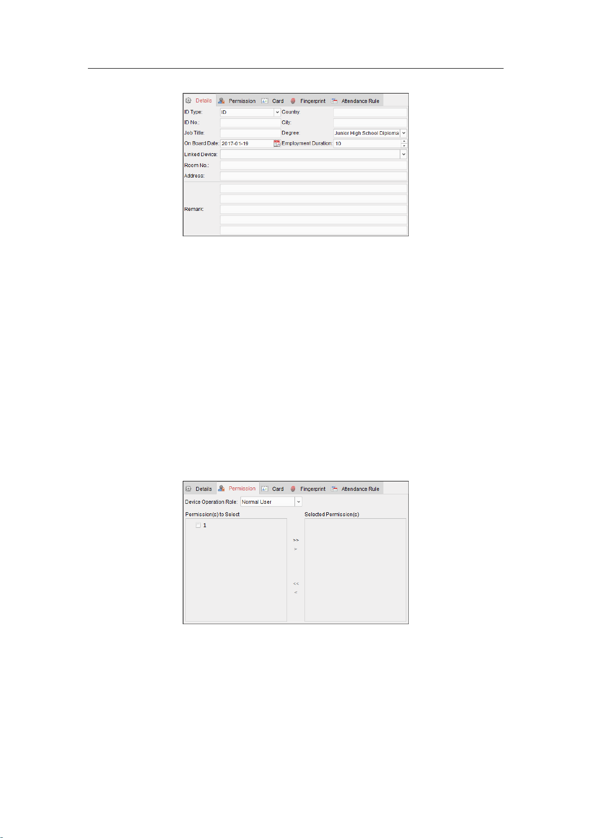
Access Control Terminal·User Manual
1. In the Add Person interface, click Details tab.
2. Input the detailed information of the person, including person’s ID type, ID No., country, etc.,
according to actual needs.
Linked Device: You can bind the indoor station to the person.
Note: If you select Analog Indoor Station in the Linked Device, the Door Station field will
display and you are required to select the door station to communicate with the analog
indoor station.
Room No.: You can input the room No. of the person.
3. Click OK to save the settings.
Adding Person (Permission)
You can assign the permissions (including operation permissions of access control device and access
control permissions) to the person when adding person.
Note: For setting the access control permission, refer to Chapter 9.5 Permission Configuration.
Steps:
1. In the Add Person interface, click Permission tab.
2. In the Device Operation Role field, select the role of operating the access control device.
Normal User: The person has the permission to check-in/out on the device, pass the access
control point, etc.
Administrator: The person has the normal user permission, as well as permission to configure the
device, including adding normal user, etc.
3. In the Permission(s) to Select list, all the configured permissions display.
Check the permission(s) checkbox(es) and click > to add to the Selected Permission(s) list.
(Optional) You can click >> to add all the displayed permissions to the Selected Permission(s) list.
68

Access Control Terminal·User Manual
(Optional) In the Selected Permission(s) list, select the selected permission and click < to remove
it. You can also click << to remove all the selected permissions.
4. Click OK to save the settings.
Adding Person (Card)
You can add card and issue the card to the person.
Steps:
1. In the Add Person interface, click Card tab.
2. Click Add to pop up the Add Card dialog.
3. Select the card type according to actual needs.
Normal Card
Card for Disabled Person: The door will remain open for the configured time period for the
card holder.
Card in Blacklist: The card swiping action will be uploaded and the door cannot be opened.
Patrol Card: The card swiping action can used for checking the working status of the
inspection staff. The access permission of the inspection staff is configurable.
Duress Card: The door can open by swiping the duress card when there is duress. At the
same time, the client can report the duress event.
Super Card: The card is valid for all the doors of the controller during the configured
schedule.
69
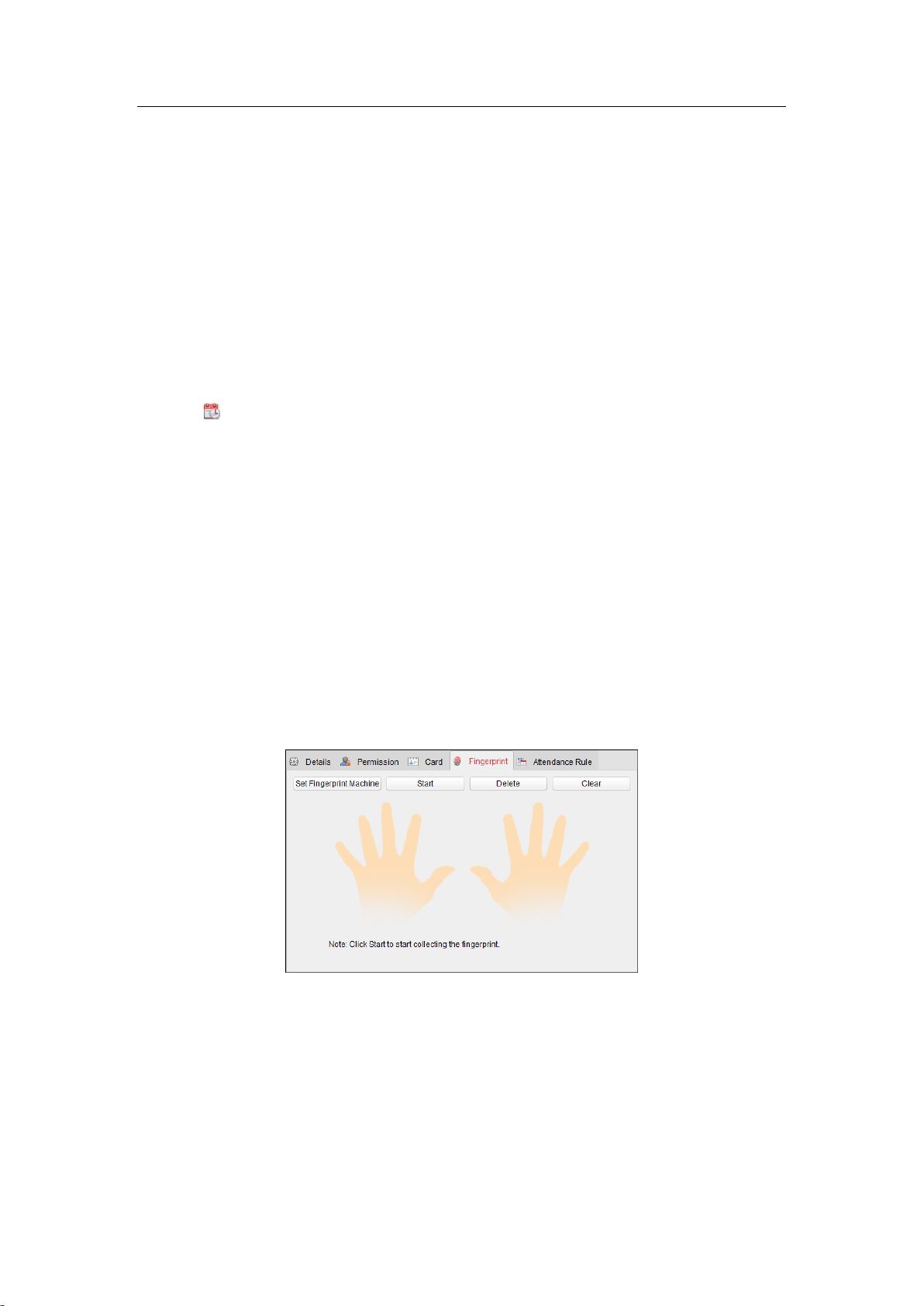
Access Control Terminal·User Manual
Visitor Card: The card is assigned for visitors. For the Visitor Card, you can set the Max.
Swipe Times.
Notes:
The Max. Swipe Times should be between 0 and 255. When your swiping card times is
more than the configured times, card swiping will be invalid.
When set the times as 0, it means the card swiping is unlimited.
4. Input the password of the card itself in the Card Password field. The card password should contain
4 to 8 digits.
Note: The password will be required when the card holder swiping the card to get enter to or exit
from the door if you enable the card reader authentication mode as Card and Password,
Password and Fingerprint, and Card, Password, and Fingerprint. For details, Chapter 9.6.2 Card
Reader Authentication.
5. Click to set the effective time and expiry time of the card.
6. Select the Card Reader Mode for reading the card No.
Access Controller Reader: Place the card on the reader of the Access Controller and click
Read to get the card No.
Manually Input: Input the card No. and click Enter to input the card No.
7. Click OK and the card(s) will be issued to the person.
8. (Optional) You can select the added card and click Edit or Delete to edit or delete the card.
9. (Optional) You can click Link Fingerprint to link the card with the person’s fingerprint, so that the
person can place the finger on the scanner instead of swiping card when passing the door.
10. Click OK to save the settings.
Adding Person (Fingerprint)
Steps:
1. In the Add Person interface, click Fingerprint tab.
2. Before inputting the fingerprint, you should connect the fingerprint machine to the PC and set its
parameters first.
Click Set Fingerprint Machine to enter the following dialog box.
70

Access Control Terminal·User Manual
1) Select the device type.
2) For fingerprint machine, you can set the serial port number, baud rate, and overtime
parameters of the fingerprint machine.
3) Click Save button to save the settings.
You can click Restore Default Value button to restore the default settings.
Notes:
The serial port number should correspond to the serial port number of PC. You can check
the serial port number in Device Manager in your PC.
The baud rate should be set according to the external fingerprint card reader. The default
value is 19200.
Timeout after field refers to the valid fingerprint collecting time. If the user does not input a
fingerprint or inputs a fingerprint unsuccessfully, the device will indicate that the fingerprint
collecting is over.
3. Click Start button, click to select the fingerprint to start collecting.
4. Lift and rest the corresponding fingerprint on the fingerprint scanner twice to collect the
fingerprint to the client.
You can also click Device Collection to collect fingerprint from the device. (The function should be
supported by the device.)
5. After collecting the fingerprint, click Card tab in Add Person window.
6. Click Link Fingerprint to link the fingerprint to the card.
You can select the registered fingerprint and click Delete to delete it.
You can click Clear to clear all fingerprints.
7. Click OK to save the fingerprints.
Adding Person (Attendance Rule)
You can set the attendance rule for the person.
Note: This tab page will display when you select Non-Residence mode in the application scene when
running the software for the first time.
Steps:
1. In the Add Person interface, click Attendance Rule tab.
71

Access Control Terminal·User Manual
2. If the person joins in the time and attendance, check the Time and Attendance checkbox to
enable this function for the person. Then the person’s card swiping records will be recorded and
analyzed for time and attendance.
For details about Time and Attendance, click More to go to the Time and Attendance module.
3. Click OK to save the settings.
Importing and Exporting Person Information
The person information can be imported and exported in batch.
Steps:
1. Exporting Person: You can export the added persons’ information in Excel format to the local PC.
1) After adding the person, you can click Export Person button in the Person and Card tab to
pop up the following dialog.
2) Click to select the path of saving the exported Excel file.
3) Check the checkboxes to select the person information to export.
4) Click OK to start exporting.
2. Importing Person: You can import the Excel file with persons information in batch from the local
PC
1) click Import Person button in the Person and Card tab.
72

Access Control Terminal·User Manual
2) You can click Download Template for Importing Person to download the template first.
3) Input the person information to the downloaded template.
4) Click to select the Excel file with person information.
5) Click OK to start importing.
Getting Person Information from Access Control Device
If the added access control device has been configured with person information (including person
details, fingerprint, issued card information), you can get the person information from the device and
import to the client for further operation.
Note: This function is only supported by the device the connection mothod of which is TCP/IP when
adding the device.
Steps:
1. In the organization list on the left, click to select an organization to import the persons.
2. Click Get Person button to pop up the following dialog box.
3. The added access control device will be displayed.
4. Click to select the device and then click OK to start getting the person information from the
device.
You can also double click the device name to start getting the person information.
Notes:
The person information, including person details, person’s fingerprint information (if configured),
and the linked card (if configured), will be imported to the selected organization.
If the person name stored in the device is empty, the person name will be filled with the issued
card No. after importing to the client.
The gender of the persons will be Male by default.
Up to 10000 persons with up to 5 cards each can be imported.
73

Access Control Terminal·User Manual
Managing Person
Modifying and Deleting Person
To modify the person information and attendance rule, click or in the Operation column, or
select the person and click Modify to open the editing person dialog.
You can click to view the person’s card swiping records.
To delete the person, select a person and click Delete to delete it.
Note: If a card is issued to the current person, the linkage will be invalid after the person is deleted.
Changing Person to Other Organization
You can move the person to another organization if needed.
Steps:
1. Select the person in the list and click Change Organization button.
2. Select the organization to move the person to.
3. Click OK to save the settings.
Issuing Card in Batch
You can issue multiple cards for the person with no card issued in batch.
Steps:
1. Click Issue Card in Batch button to enter the following dialog.
All the added person with no card issued will display in the Person(s) with No Card Issued list.
74

Access Control Terminal·User Manual
2. Select the card type according to actual needs.
Note: For details about the card type, refer to Adding Person.
3. Input the password of the card itself in the Card Password field. The card password should
contain 4 to 8 digits.
Note: The password will be required when the card holder swiping the card to get enter to or exit
from the door if you enable the card reader authentication mode as Card and Password,
Password and Fingerprint, and Card, Password, and Fingerprint. For details, refer to Chapter
9.6.2 Card Reader Authentication.
4. Input the card quantity issued for each person.
For example, if the Card Quantity is 3, you can read or enter three card No. for each person.
5. Click to set the effective time and expiry time of the card.
6. Select the Card Reader Mode for reading the card No.
Access Controller Reader: Place the card on the reader of the Access Controller and click
Read to get the card No.
Manually Input: Input the card No. and click Enter to input the card No.
7. After issuing the card to the person, the person and card information will display in the Person(s)
with Card Issued list.
8. Click OK to save the settings.
9.4 Schedule and Template
Purpose:
You can configure the template including week schedule and holiday schedule. After setting the
templates, you can adopt the configured templates to access control permissions when setting the
permission, so that the access control permission will take effect in the time durations of the
template.
75
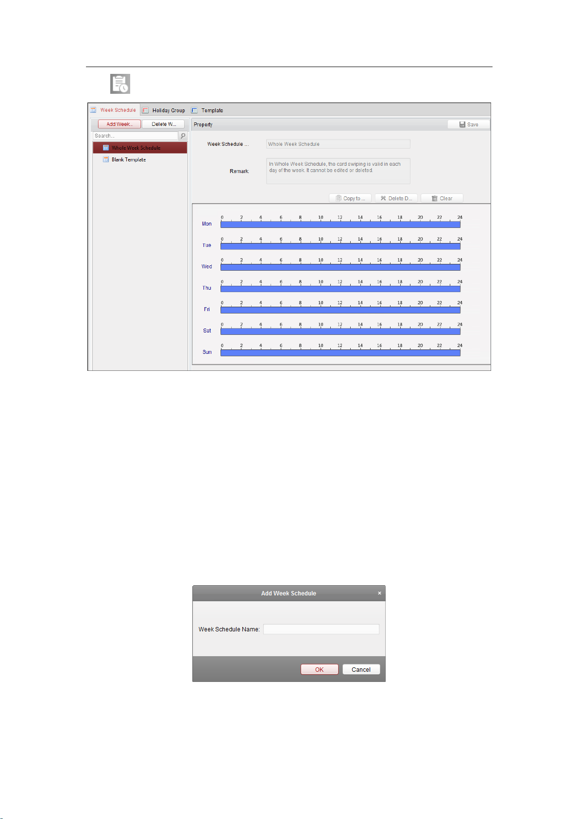
Access Control Terminal·User Manual
Click to enter the schedule and template interface.
You can manage the schedule of access control permission including Week Schedule, Holiday Schedule,
and Template. For permission settings, please refer to Chapter 9.5 Permission Configuration.
9.4.1 Week Schedule
Click Week Schedule tab to enter the Week Schedule Management interface.
The client defines two kinds of week plan by default: Whole Week Schedule and Blank Schedule,
which cannot be deleted and edited.
Whole Week Schedule: Card swiping is valid on each day of the week.
Blank Schedule: Card swiping is invalid on each day of the week.
You can perform the following steps to define custom schedules on your demand.
Steps:
1. Click Add Week Schedule button to pop up the adding schedule interface.
2. Input the name of week schedule and click OK button to add the week schedule.
3. Select the added week schedule in the schedule list and you can view its property on the right.
You can edit the week schedule name and input the remark information.
4. On the week schedule, click and drag on a day to draw on the schedule, which means in that
76

Access Control Terminal·User Manual
period of time, the configured permission is activated.
Note: Up to 8 time periods can be set for each day in the schedule.
5. When the cursor turns to , you can move the selected time bar you just edited. You can also
edit the displayed time point to set the accurate time period.
When the cursor turns to , you can lengthen or shorten the selected time bar.
6. Optionally, you can select the schedule time bar,
and then click Delete Duration to delete the selected time bar,
or click Clear to delete all the time bars,
or click Copy to Week to copy the time bar settings to the whole week.
7. Click Save to save the settings.
9.4.2 Holiday Group
Click Holiday Group tab to enter the Holiday Group Management interface.
Steps:
1. Click Add Holiday Group button on the left to pop up the adding holiday group interface.
2. Input the name of holiday group in the text filed and click OK button to add the holiday group.
3. Select the added holiday group and you can edit the holiday group name and input the remark
information.
77

Access Control Terminal·User Manual
4. Click Add Holiday icon on the right to add a holiday period to the holiday list and configure the
duration of the holiday.
Note: Up to 16 holidays can be added to one holiday group.
1) On the period schedule, click and drag to draw the period, which means in that period of
time, the configured permission is activated.
Note: Up to 8 time durations can be set for each period in the schedule.
2) When the cursor turns to , you can move the selected time bar you just edited. You can
also edit the displayed time point to set the accurate time period.
3) When the cursor turns to , you can lengthen or shorten the selected time bar.
4) Optionally, you can select the schedule time bar,
and then click to delete the selected time bar,
or click to delete all the time bars of the holiday,
or click to delete the holiday directly.
5. Click Save to save the settings.
Note: The holidays cannot be overlapped with each other.
9.4.3 Template
After setting the week schedule and holiday group, you can configure the template which contains
week schedule and holiday group schedule.
Note: The priority of holiday group schedule is higher than the week schedule.
Click Template tab to enter the Template Management interface.
78

Access Control Terminal·User Manual
There are two pre-defined templates by default: Whole Week Template and Blank Template, which
cannot be deleted and edited.
Whole Week Template: The card swiping is valid on each day of the week and it has no holiday
group schedule.
Blank Template: The card swiping is invalid on each day of the week and it has no holiday group
schedule.
You can define custom templates on your demand.
Steps:
1. Click Add Template to pop up the adding template interface.
2. Input the template name in the text filed and click OK button to add the template.
3. Select the added template and you can edit its property on the right. You can edit the template
name and input the remark information.
4. Select a week schedule to apply to the schedule.
Click Week Schedule tab and select a schedule in the dropdown list.
You can also click Add Week Schedule to add a new week schedule. For details, refer to Chapter
9.4.1 Week Schedule.
79

Access Control Terminal·User Manual
5. Select holiday groups to apply to the schedule.
Note: Up to 4 holiday groups can be added.
Click to select a holiday group in the list and click Add to add it to the template. You can also click
Add Holiday Group to add a new one. For details, refer to Chapter 9.4.2 Holiday Group.
You can click to select an added holiday group in the right-side list and click Delete to delete it.
You can click Clear to delete all the added holiday groups.
6. Click Save button to save the settings.
9.5 Permission Configuration
In Permission Configuration module, you can add, edit, and delete the access control permission, and
then apply the permission settings to the device to take effect.
Click icon to enter the Access Control Permission interface.
80

Access Control Terminal·User Manual
9.5.1 Adding Permission
Purpose:
You can assign permission for persons to enter/exist the access control points (doors) in this section.
Steps:
1. Click Add icon to enter following interface.
2. In the Permission Name field, input the name for the permission as desired.
3. Click on the dropdown menu to select a template for the permission.
Note: You should configure the template before permission settings. You can click Add Template
button to add the template. Refer to Chapter 9.4 Schedule and Template for details.
4. In the Person list, all the added persons display.
Check the checkbox(es) to select person(s) and click > to add to the Selected Person list.
(Optional) You can select the person in Selected Person list and click < to cancel the selection.
5. In the Access Control Point/Device list, all the added access control points (doors) and door
stations will display.
Check the checkbox(es) to select door(s) or door station(s) and click > to add to the selected list.
(Optional) You can select the door or door station in the selected list and click < to cancel the
selection.
6. Click OK button to complete the permission adding. The selected person will have the permission
to enter/exit the selected door/door station with their linked card(s) or fingerprints.
7. (Optional) after adding the permission, you can click Details to modify it. Or you can select the
81

Access Control Terminal·User Manual
permission and click Modify to modify.
You can select the added permission in the list and click Delete to delete it.
9.5.2 Applying Permission
Purpose:
After configuring the permissions, you should apply the added permission to the access control device
to take effect.
Steps:
1. Select the permission(s) to apply to the access control device. To select multiple permissions, you
can hold the Ctrl or Shift key and select permissions.
2. Click Apply to Device to start applying the selected permission(s) to the access control device or
door station.
3. The following window will pop up, indicating the applying permission result.
9.6 Advanced Functions
Purpose:
After configuring the person, template, and access control permission, you can configure the
advanced functions of access control application, such as access control parameters, authentication
password, and opening door with first card, anti-passing back, etc.
Note: The advanced functions should be supported by the device.
Click icon to enter the following interface.
82

Access Control Terminal·User Manual
9.6.1 Access Control Parameters
Purpose:
After adding the access control device, you can configure its access control point (door)’s parameters,
and its card readers’ parameters.
Click Access Control Parameters tab to enter the parameters settings interface.
Door Parameters
Steps:
1. In the controller list on the left, click to expand the access control device, select the door
(access control point) and you can edit the information of the selected door on the right.
2. You can editing the following parameters:
83

Access Control Terminal·User Manual
Door Magnetic: The Door Magnetic is in the status of Remain Closed (excluding special
conditions).
Exit Button Type: The Exit Button Type is in the status of Remain Open (excluding special
conditions).
Door Locked Time: After swiping the normal card and relay action, the timer for locking the door
starts working.
Door Open Duration by Card for Disabled Person: The door magnetic can be enabled with
appropriate delay after disabled person swipes the card.
Door Open Timeout Alarm: The alarm can be triggered if the door has not been close
Enable Locking Door when Door Closed: The door can be locked once it is closed even if the
Door Locked Time is not reached.
Duress Code: The door can open by inputting the duress code when there is duress. At the same
time, the client can report the duress event.
Super Password: The specific person can open the door by inputting the super password.
Dismiss Code: Input the dismiss code to stop the buzzer of the card reader.
Notes:
The duress code, Super password, and dismiss code should be different.
The duress code, super password, and the dismiss code should be different from the
authentication password.
The duress code, super password, and the dismiss code should contain 4 to 8 numerics.
3. Click Save button to save parameters.
Card Reader Parameters
Steps:
1. In the device list on the left, click to expand the door, select the card reader name and you
can edit the card reader parameters on the right.
84

Access Control Terminal·User Manual
2. You can editing the following parameters:
Nickname: Edit the card reader name as desired.
Enable Card Reader: Select Yes to enable the card reader.
OK LED Polarity: Select the OK LED Polarity of the card reader mainboard.
Error LED Polarity: Select the Error LED Polarity of the card reader mainboard.
Buzzer Polarity: Select the Buzzer LED Polarity of the card reader mainboard.
Minimum Card Swiping Interval: If the interval between card swiping of the same card is less
than the set value, the card swiping is invalid. You can set it as 0 to 255.
Max. Interval When Inputting Password: When you inputting the password on the card reader, if
the interval between pressing two digits is larger than the set value, the digits you pressed before
will be cleared automatically.
Enable Failed Attempts Limit of Card Reading: Enable to report alarm when the card reading
attempts reach the set value.
Max. Times of Card Swiping Failure: Set the max. failure attempts of reading card.
Enable Tampering Detection: Enable the anti-tamper detection for the card reader.
Detect When Card Reader is Offline for: When the access control device cannot connect with the
card reader for longer than the set time, the card reader will turn offline automatically.
Fingerprint Recognition Level: Select the fingerprint recognition level in the dropdown list. By
default, the level is Low.
Card Reader Type: Read the card reader’s type.
Card Reader Description: Read the card reader description.
Buzzing Time: Set the card reader buzzing time. The available time ranges from 0 to 5999s. 0
represents continuous buzzing.
3. Click the Save button to save parameters.
85

Access Control Terminal·User Manual
9.6.2 Card Reader Authentication
Purpose:
You can set the passing rules for the card reader of the access control device.
Steps:
1. Click Card Reader Authentication tab and select a card reader on the left.
2. Select a card reader authentication mode. The available authentication modes depend on the
card reader type:
Card and Password: The door can open by both inputting the card password and swiping
the card.
Note: Here the password refers to the password set when issuing the card to the person.
Chapter 9.3.2 Person Management.
Card or Authentication Password: The door can open by inputting the authentication
password or swiping the card.
Note: Here the authentication password refers to the password set to open the door. Refer
to Chapter 9.6.8 Authentication Password.
Fingerprint: The door can open by only inputting the fingerprint.
Card: The door can open by only swiping the card.
Card or Fingerprint: The door can open by inputting the fingerprint or swiping the card.
Password and Fingerprint: The door can open by both inputting the card password and
inputting the fingerprint.
Note: Here the password refers to the card password set when issuing the card to the
person. Refer to Chapter 9.3.2 Person Management.
Card and Fingerprint: The door can open by both inputting the fingerprint and swiping the
card.
Card, Password and Fingerprint: The door can open by both inputting the fingerprint,
inputting the card password, and swiping the card.
Note: Here the password refers to the card password set when issuing the card to the
person. Refer to Chapter 9.3.2 Person Management.
3. Click and drag your mouse on a day to draw a color bar on the schedule, which means in that
period of time, the card reader authentication is valid.
86

Access Control Terminal·User Manual
4. Repeat the above step to set other time periods.
Or you can select a configured day and click Copy to Week button to copy the same settings to
the whole week.
(Optional) You can click Delete button to delete the selected time period or click Clear button to
delete all the configured time periods.
5. (Optional) Click Copy to button to copy the settings to other card readers.
6. Click Save button to save parameters.
9.6.3 Multiple Authentication
Purpose:
You can manage the cards by group and set the authentication for multiple cards for one access
control point (door).
87

Access Control Terminal·User Manual
Note: Please set the card permission and apply the permission setting to the access control device
first. For details, refer to Chapter 9.5 Permission Configuration.
Steps:
1. Click Multiple Authentication tab to enter the following interface.
2. Select access control device from the list on the left.
3. In the Set Card Group panel on the right, click Add button to pop up the following dialog:
1) In the Card Group Name field, input the name for the group as desired.
2) Click to set the effective time and expiry time of the card group.
3) Check the checkbox(es) to select the card(s) to add the card group.
88

Access Control Terminal·User Manual
4) Click OK to save the card group.
4. In the Set Authentication Group panel on the left, click Add to pop up the following dialog.
1) Select the access control point (door) of the device for multiple authentication.
2) Input the time interval for card swiping.
3) Select the template of the authentication group from the dropdown list. For details about
setting the template, refer to Chapter 9.4 Schedule and Template.
4) Select the authentication type of the authentication group from the dropdown list.
Local Authentication: Authentication by the access control device.
Local Authentication and Remotely Open Door: Authentication by the access control
device and by the client.
For Local Authentication and Remotely Open Door type, you can check the checkbox to
enable the super password authentication when the access control device is
disconnected with the client.
Local Authentication and Super Password: Authentication by the access control device
and by the super password.
5) In the list on the left, the added card group will display. You can click the card group and click
to add the group to the authentication group.
You can click the added card group and click to remove it from the authentication group.
You can also click or to set the card swiping order.
5) Input the Card Swiping Times for the selected card group.
Notes:
The Card Swiping Times should be larger than 0 and smaller than the added card
quantity in the card group.
The upper limit of Card Swiping Times is 16.
6) Click OK to save the settings.
5. Click Save to save and take effect of the new settings.
89

Access Control Terminal·User Manual
Notes:
For each access control point (door), up to four authentication groups can be added.
For the authentication group which certificate type is Local Authentication, up to 8 card groups
can be added to the authentication group.
For the authentication group which certificate type is Local Authentication and Super Password
or Local Authentication and Remotely Open Door, up to 7 card groups can be added to the
authentication group.
9.6.4 Open Door with First Card
Purpose:
You can set multiple first cards for one access control point. After the first card swiping, it allows
multiple persons access the door or other authentication actions. The first card mode contains Remain
Open with First Card, Disable Remain Open with First Card, and First Card Authorization.
Remain Open with First Card: The door remains open for the configured time duration after the first
card swiping until the remain open duration ends.
First Card Authorization: All authentications, except for the authentications of super card, duress card,
and duress code, are allowed only after the first card authorization.
Steps:
1. Click Open Door with First Card tab to enter the following interface.
2. Select an access control device from the list on the left.
3. Check the checkbox of Enable First Card Remain Open to enable this function.
4. (Optional) If you select Remain Open with First Card, you should set remain open duration.
Notes:
The Remain Open Duration should be between 0 and 1440 minutes. By default, it is 10
minutes.
In the First Card Authorization mode, you can access the door when swiping the super card,
the duress card or input the duress code without swiping the first card.
You can swipe the first card again to disable the first card mode.
The first card authorization is effective only on the current day. The authorization will be
expired after 24:00 on the current day.
90

Access Control Terminal·User Manual
5. In the First Card list, Click Add button to pop up the following dialog box.
1) Select the cards to add as first card for the door
Note: Please set the card permission and apply the permission setting to the access control
device first. For details, refer to Chapter 9.5 Permission Configuration.
2) Click OK button to save adding the card.
6. You can click Delete button to remove the card from the first card list.
7. Click Save to save and take effect of the new settings.
9.6.5 Anti-Passing Back
Purpose:
You can set anti-passing back for card readers in the same access controller. You should swipe the card
according to the configured swiping card route. And only one person could pass the access control
point after swiping the card.
Notes:
Either the anti-passing back or multi-door interlocking function can be configured for an access
control device at the same time.
You should enable the anti-passing back function on the access control device first.
Setting the Path of Swiping Card (Card Reader Order)
Steps:
1. Click Anti-passing Back tab to enter the following interface.
91

Access Control Terminal·User Manual
2. Select an access control device from the device list on the left.
3. In the First Card Reader field, select the card reader as the beginning of the path.
4. In the list, click the text filed of Card Reader Afterward and select the linked card readers.
Example: If you select Reader In_01 as the beginning, and select Reader In_02, Reader Out_04 as
the linked card readers. Then you can only get through the access control point by swiping the
card in the order as Reader In_01, Reader In_02 and Reader Out_04.
Note: Up to four afterward card readers can be added for one card reader.
5. (Optional) You can enter the Select Card Reader dialog box again to edit its afterward card
readers.
6. Click Save to save and take effect of the new settings.
9.6.6 Cross-Controller Anti-passing Back
Purpose:
You can set anti-passing back for card readers in multiple access controllers. You should swipe the card
92
 Loading...