

Page 1
Page 2
SPECIFICATIONS
Operating Frequency
315mhz
Number of Codes
1,048,576
Data Format
PWM
Operating Voltage
DC12V
Operating Distance
Up to 150 Feet (45M)
Operating Temperature
0°C-70°C or 32°F - 158°F
Current Draw
19mA
RF channels
Two
No. of Remotes that are able to
connect to one Receiver
up to 50
Receiver Output
C dry contact (NO/NC/COM)
Receiver Output Functions
4 (Default) 4 second momentary,
latch, toggle (On/Off),
press on function
Connectors
5 screw Terminal (NO, COM, NC + -)
(short wire included for each terminal used
to facilitate install.)
Case Construction
ABS Plastic
Dimensions
62*43.5*30mm (2.44* 1.71*1.18 Inches)
Weight
43g or 1.52 Ounces
Certifications
FCC
Antenna
Wire lead
Mounting Screws
Comes with two mounting screws
Warranty
3 Year
Wire Harness
Included
Power supply
Not included
(only included in the form of kits.)
DESCRIPTION
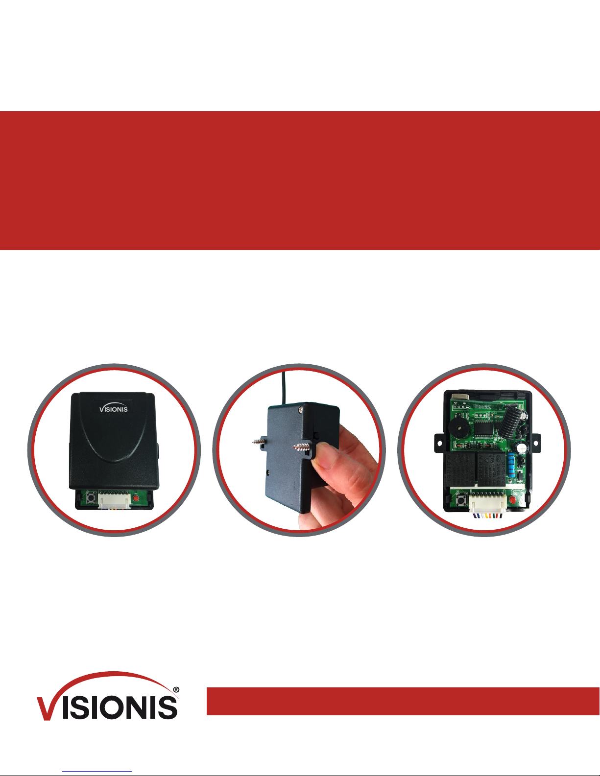
The Visionis VIS-8007 RF Wireless Receiver was built to feed the demand for a device that
can meet multiple functions without having to purchase additional devices. The VIS-8007 RF
receiver can be used to control all sorts of Electrical devices such as Garage Door Openers,
Lights, Motorized Gates, Mag Locks, Electric Strikes, Lifts and many more devices.
NOTES FOR INSTALLATION
Do not install the receiver where it is exposed to weather or moisture conditions.
Do not install the receiver near metal which will reduce the range of the receiver
In order to receive the proper range, you must pull the Antenna as straight as you can.
Do not cut or take off the antenna.
Page 3
INSTRUCTIONS TO PROGRAM A NEW
TRANSMITTER ( REMOTE CONTROL)
Each VIS-8007 Visionis receiver can program up to 50 transmitters (remotes) (VIS-8008 and
VIS-8005).
Before you program this function make sure you have one of your remotes on hand.
Now press the “Learning Button” once and release it right away. Then immediately press
the button on the remote one time and release it.
After that has been done, you will see the LED light on the receiver quickly flash and this
means that the remote has been programmed.
The receiver can hold as many as 50 remotes at the same time simultaneously.
Deleting Remotes
If your remote has been lost or misplaced or you need to delete it from the receiver for any
Reason, go ahead and press the “Learning Button” for about 8 seconds until you see that
the red solid light goes away.
Warning: This feature will delete all the remotes that you have programmed. If you have other
IMPORTANT NOTES
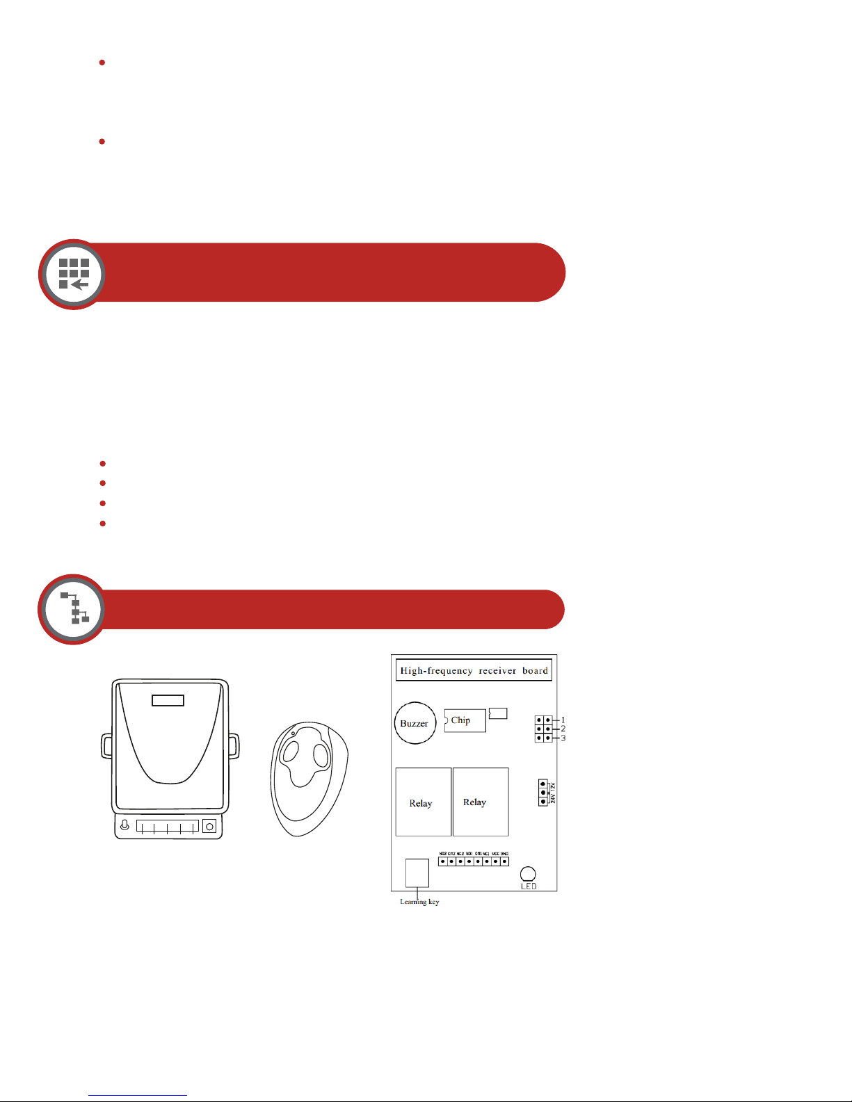
On the following page you will find a diagram on where you can identify the program-
ming button on the receiver.
• If the button on the transmitter (remote) is not pressed within 15 seconds of the LED
light flashing, the receiver will exit programming and the LED light will turn off.
• If the transmitter (remote) has been programmed already, you will see the receivers
channel light turn on steadily and then start flashing again. The transmitter (remote) will
not be able to be programmed a second time.
• One receiver can program up to 50 transmitters (remotes).
PROGRAMMING DIFFERENT
FUNCTIONS ON THE RECEIVER
The receiver can be programmed to five different functions. To locate the function mode
button on the receiver look at the diagram on the following page.
4-Second Delay Function (this is the Default Function): When the transmitter (remo-
te) button is pressed, the receiver will turn on for 4 seconds and automatically turn off
after the 4 seconds.
Press on Function: As long as the Transmitter (remote) Button is pressed, the receiver
will stay on.
Page 4
ON/ Off Toggle Function (L): This function works exactly like an on/off switch. When the
Transmitter (remote) button is pressed once, the receiver turns on. When the transmitter
(remote) is pressed again the relay turns off.
Latch: Press transmitter button A, the receiver relay A is on, Press transmitter button B,
the receiver relay A will stop work.
SELECTING THE DIFFERENT BLACK
JUMPER FUNCTION ON THE RECEIVER
To program the correct function on your receiver you must take off the main black
cap of the receiver. On the right-hand side, you will find three little Jumper terminals. The
terminals are defined below. To implement the function needed simply remove the black
jumper and put it on the terminal function of your choosing.
Jumper Definitions
A. Signal Self-locking = 2 connect, 1,3 disconnect
B. Signal Interlock = 1 connect, 2,3 disconnect
C. Signal Inching = 1,2,3 all disconnected
D. Relay for 3 seconds = 3 connect, 1,2 disconnect
WIRING DIAGRAM
Wire Definition:
C = Blue: NO
B = Yellow: Com
A = White: NC
Red: +
Black: -
Page 5
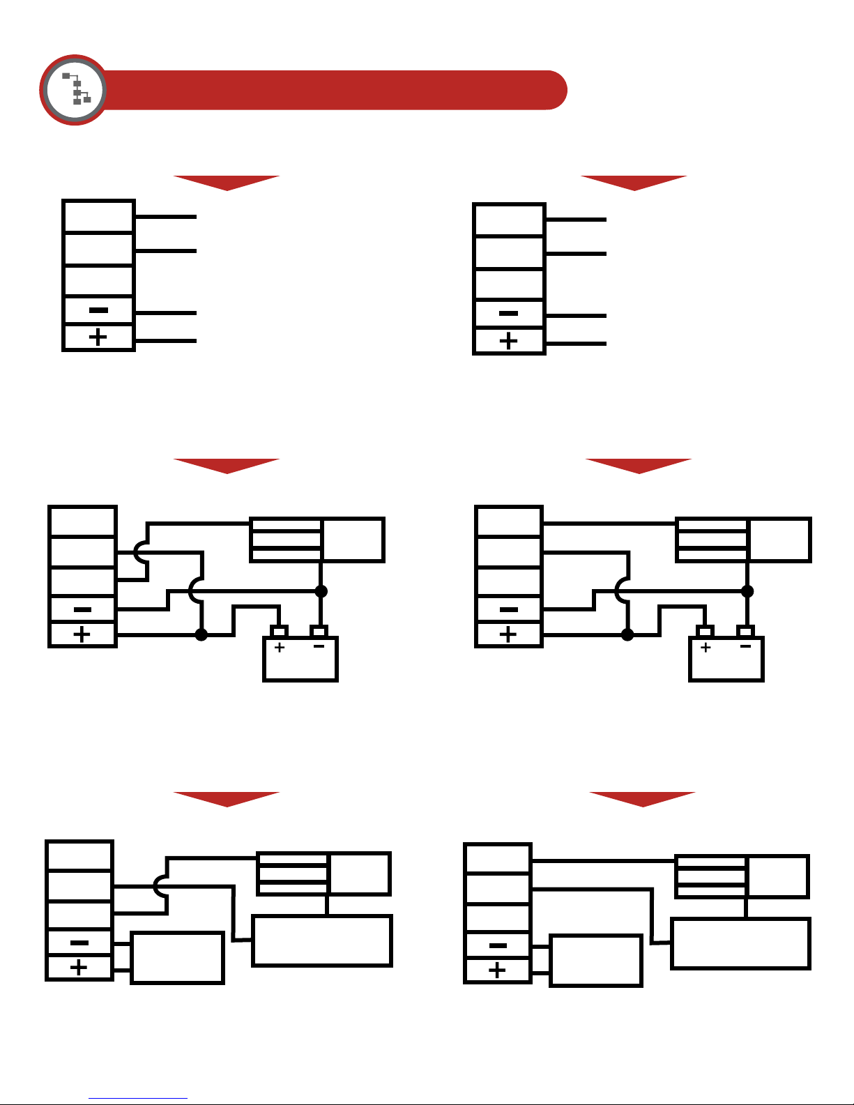
DIFFERENT TYPE OF APPLICATION
NO
COM
NC
NO
COM
Positive Output
Positive Power Sources
Positive Power Output
NO
COM
Negative Output
Negative Power Sources
Negative Power Output
NC
Power
Typical N.C. Application Typical N.O. Application
Magnetic locks
NO
COM
Power
Magnetic locks
NC
12VDC
N.C. Application with independent
Power Sources
Magnetic locks
NO
COM
NC
DC POWER
AC POWER
SOURCES
SOURCES
NC
12VDC
N.O. Application with independent
Power Sources
Magnetic locks
NO
COM
NC
DC POWER
AC POWER
SOURCES
SOURCES
 Loading...