

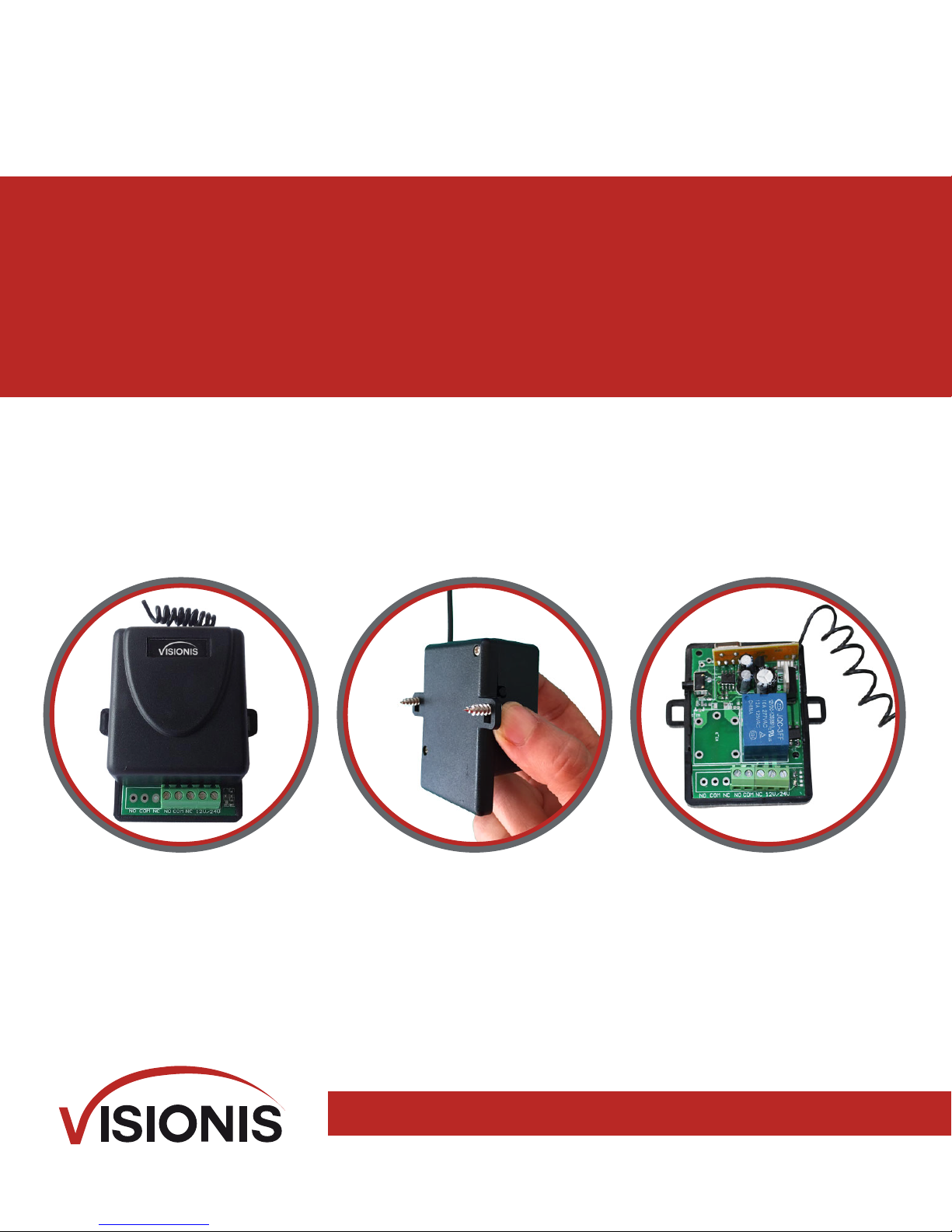
One Channel Receiver 315mhz
VIS-8004
USER MANUAL
For support: sales@visionistech.com

SPECIFICATIONS
Operating Frequency
315mhz
Number of Codes
1,048,576
Data Format
PWM
Operating Voltage
+12V 24V
Operating Distance
Up to 320 Feet (100M)
Operating Temperature
0°C-70°C or 32°F - 158°F
Current Draw
19mA
Sensitivity
-100DB
Compatible Transmitter
VIS-8005
RF channels
One
No. of Remotes that are able to
connect to one Receiver
up to 20
Receiver Output
C dry contact (NO/NC/COM)
Receiver Output Functions
5 (Default) 4 second momentary, 1-sec
momentary, toggle, validity, latch
Connectors
5 screw Terminal (NO, COM, NC + -)
Case Construction
ABS Plastic
Dimensions
63mm*45mm*30mm
(2.4Inches* 1.77Inches*1.18inches)
Weight
43g or 1.52 Ounces
Certifications
FCC
Antenna
Wire lead
Mounting Screws
Comes with two mounting screws
Warranty
1 Year
DESCRIPTION
The Visionis VIS-8004 RF Wireless Receiver was built to feed the demand for a device that
can meet multiple functions without having to purchase additional devices. The VIS-8004 RF
receiver can be used to control all sorts of Electrical devices such as Garage door Openers,
Lights, Motorized gates, Mag locks, Electric Strikes, lifts and many more devices.
NOTES FOR INSTALLATION
Do not install the receiver where it is exposed to weather or moisture conditions.
Do not install the receiver near metal which will reduce the range of the receiver
In order to receive the proper range, you must pull the Antenna as straight as you can.
Do not cut or take off the antenna.

INSTRUCTIONS TO PROGRAM A NEW
TRANSMITTER ( REMOTE CONTROL)
Each VIS-8004 Visionis receiver can program up to 20 Transmitters (remotes) (VIS-8005)
Make sure that while you are programming the transmitter (remote) you have the
remote in your hands ready to be programmed.
Press the programming switch for 3 seconds or more. The channel’s LED will start to
flash quickly. This will indicate that it is in programming mode.
When the LED light begins to Flash, Press the button of the Transmitter (remote) to
be programmed one time. The receiver’s Channel light will flash once to show that that
the transmitter (remote) has been programmed successfully. After the transmitter
(remote) has been programmed the receiver will automatically exit the programming
mode.
IMPORTANT NOTES
On the following page you will find a diagram on where you can identify the programming
button on the receiver.
If the button on the Transmitter (remote) is not pressed within 15 seconds of the LED
light flashing. The receiver will exit programming and LED light will turn off.
If the Transmitter (remote) has been programmed already. You will see the receivers
channel Light turn steady on and then start flashing again. The Transmitter (remote) will
not be able to be programmed a second time.
One receiver can program up to 20 Transmitter (remotes)
CLEAR RECEIVER MEMORY
To clear all the Transmitter (remotes) from the receiver's Memory. Press the Programming
Switch for 6 seconds or until the LED light starts to Flash Repeatedly.
PROGRAMMING DIFFERENT
FUNCTIONS ON THE RECEIVER
The receiver can be programmed to five different functions. To locate the function mode
button on the receiver look at the diagram on the following page.
4-second delay Function (this is the Default Function): When The Transmitter (remote)
button is pressed, the receiver will turn on for 4 seconds and automatically turn off after
the 4 seconds.
ON/ Off Toggle Function: This function works exactly like an on/off switch. When the
Transmitter (remote) button is pressed once, the receiver turns on. When the Transmit
ter (remote) is pressed again the relay turns off.
Clamp Function: When The Transmitter (remote) button is pressed once the receiver
turns ON and stays ON. The receiver will remain on regardless if another remote is pres
sed. To turn OFF the receiver Press the Receiver function mode button once and the
device will reset.
Press on Function: As long as the Transmitter (remote) Button is pressed, the receiver will
stay on.
1 second delay Function: When the Transmitter (remote) button is pressed, the receiver
will turn on for 1 second and automatically turn off after the 1 second.
SELECTING THE DIFFERENT
FUNCTION ON THE RECEIVER
The Function button can be found by looking at the diagram below:
4-second Delay Function (this is the Default)
1 Flash
ON/ Off Toggle Function
2 Flashes
Clamp Function
3 Flashes
Press down on the channel Function Button for 3 or more seconds. The channel’s LED
light will flash a number of times equal to the output it is in.
In order to Change the channels function on the receiver, press the channels function
Switch. Each press moves the receiver to the next function.
After setting the function of choice, verify the number of flashes in order to make sure
that the proper function has been selected.
Wait for 15 seconds so the receiver can exit the function Programming.
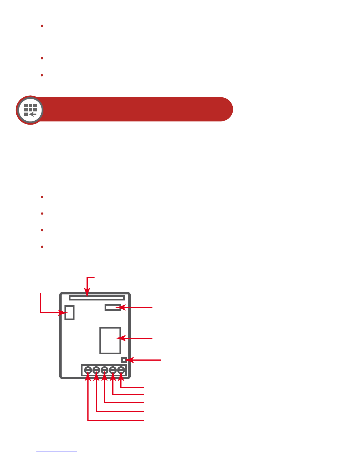
Programming
Receiver
Switch
Press on Function
4 Flashes
Function
Switch
1 Second Delay Function
5 Flashes
LED INDICATION
Steady ON: Receiving signal from the
Transmitter (remote). This verifies
that that the Transmitters (remotes)
code is programmed in the receiver's
memory during programming of the
Transmitter (remote).
Relay
+
NC
COM
NO
LED
Indicator
Fast Flash: This verifies that the recei-
ver is in programming mode for the
Transmitter (remote).
One Flash: A transmitter (remote) was
programmed.
Two Flashes: All Previously Program-
med Transmitter (remote) were deleted.

DIFFERENT TYPE OF APPLICATION
NO
COM
NC
NO
COM
Positive Output
Positive Power Sources
Positive Power Output
NO
COM
Negative Output
Negative Power Sources
Negative Power Output
NC
Power
Typical N.C. Application Typical N.O. Application
Magnetic locks
NO
COM
Power
Magnetic locks
NC
12VDC
N.C. Application with independent
Power Sources
Magnetic locks
NO
COM
NC
DC POWER
AC POWER
SOURCES
SOURCES
NC
12VDC
N.O. Application with independent
Power Sources
Magnetic locks
NO
COM
NC
DC POWER
AC POWER
SOURCES
SOURCES
 Loading...