

Page 1
Standalone Access Control
for Single Door
VIS-3000
User Manual
VIS-3000
www.visionistech.com
VIS-3003
VIS-3003
Page 2
1. Description
The device is a standalone as well as a Wiegand access control keypad and
proximity card reader which supports EM, HID,and Mifare card types,it’s
one of the most advanced standalone access control .Its build-in USA Atmel
microprocessor,with strong anti-interference ability, high security and reliability,
powerful function and convenient operation.It is widely used in high-end buildings,
residential communities and other public places. This device can be used as standalone
and connected to a central Access Control Panel.
2. Features
• Ultra-low power consumption: Standby current is less than 30mA.
• Input& Output: Wiegand26.
• Searching Time: Less than 0.1s after reading card.
• Backlight Keypad: Easy to operate at night.
• Doorbell interface: Support external wired doorbell.
• Access ways: Card, code, card+code.
• Independent codes: Use codes without related card.
• Change Codes: Users can change codes by themselves.
• Anti-tamper alarm: Alarm is activated after tear down illegally.
• Delete Users by card NO.: Delete card NO. by keypad to eliminate security risk
completely.
3. Specification
• Input Voltage: DC 12V
• Idle Current:≤25mA
• Card reading distance: 2-3 cm
• Card Frequency: 125KHz for EM and HID,13.56MHz for Mifare
• Card transmission format: wiegand26
• Keypad transmission format:4bit,8bit and Virtual card number
• Operating Temperature: -45°C~55° C (-49F – 131F)
• Operating Humidity: 0%~95%
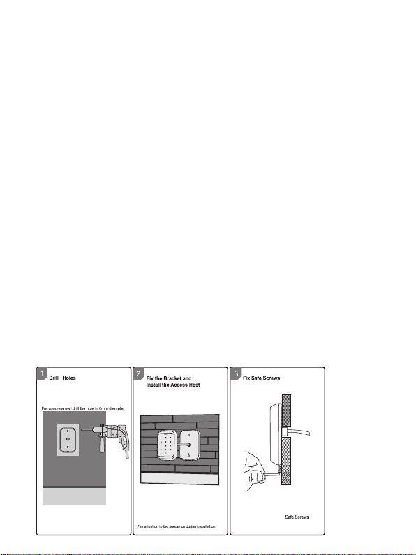
4. Installation
Install base plate onto wall and attach device using bottom screw
1
Page 3

5. Wiring
Operation
Buzzer
Standby
Press key
Di
Read card
Green
Di-
Door Open
Green
Di-
Operation Successful
Green
Di-
Operation Failed
Di Di Di
PIN Inputting
Red
Card&PIN Inputting
Red
Multi Card Reading
Red
Under Menu
Red
Under Setting
Orange
Manager Card Enter
Orange
Di Di
Manager Card Exit
Red Flash
Di-
Alarm
Red Quick Flash
Alarm
No. Marks Color Description
1 BELL_A Pink Doorbell button
2 BELL_B Pink Doorbell button
3 D0 Green Wiegand output D0
4 D1 White Wiegand output D1
5 +12V Red Positive pole of power supply
6 GND Black Negative pole of power supply
7 OPEN Yellow Exit button
8 D_IN Brown Door contact
9 ALARM Gray Alarm Output
10 NO Blue Relay NO end
11 COM Purple Relay Com end
12 NC Orange Relay NC end
6. Sound and Light Indication
LED Color
Red flash
2
Page 4

7. Quick Programming Guide
7.1 Administrator Setting
StandbyMaster
Red
Flash
*
Code
Red
Master
code#
(Code
length:
6-8
digits)
Menu
Red
00
01
02
03
05
07
51
7.2 System Setting
Stand
Master
by
Red
Flash
Master
code#
(Code
length:
*
6-8
digits)
Code
Red
Menu
Red
30
31
32
33
34
35
Setting
Orange
New master code#
Repeat new master
code #
Read Manager Add
Card
Read Manager
Delete Card
Read Anti-duress
card
Anti-duress PIN#
0000#
Setting
Orange
0-15 #
0 #
1 #
5 #
26 #
0-2 #
1-3 #
0 #
1 #
2 #
Remarks
Default 0
Unable to
initialize
Default 26
Unable to
initialize
Default 1
Default 0
3
Remarks
Factory
default:
999999
To set facility code
Wiegand reader mode
Standalone mode (factory
default setting)
Anti-passback mode
To set Wiegand format
To set keypad transmission
format
To set alarm time
Safe mode 0
Safe mode 1
Safe mode 2
Functions
Change the master
code
Set Manager Add
Card
Set Manager Delete
Card
Set Anti-duress card
Set Anti-duress PIN
Delete All Users
Master open Lock
Functions
Page 5

7.3 User Setting
Master
Stand
Code
by
Red
Red Red
Flash
Master
code#
(Code
*
length:
6-8
digits)
Menu Setting Remarks Functions
Orange
Read card #
ID number # read
card#
11
Card number #
ID number # card
number #
ID number #
PIN #
Read card #
ID number #
12
Card number #
0 #
13
1 #
2 #
0-99 #
14
0 #
15
1 #
1-10 #
16
Users can be
added continuously
without exiting
programming
mode
Users can be
deleted
continuously
without exiting
programming
mode
Default 2
Default 5
Default 0
Default 1
To add card users
To add PIN users
To delete users
Entry by Card
Entry by card+PIN
Entry by Card or
PIN
Set door relay
time
Relay Setting-Pulse
mode
Relay Setting-Toggle
mode
To set open door
by multi cards
ID number#,
card number#,
17
card quantity#
4
To add a series
cards users
Page 6

7.4 User Optional Setting
Stand
Master
by
Code
Red
Red
Flash
Master
code#
(Code
length:
*
6-8
digits)
Instruction:
1. Master code must be 6-8 digits, Anti-duress PIN must be 8 digits, user PIN is
4-6 digits.
2. The user ID number is 1-4 digits ,which can be any number among 1-2000,Invalid
0 can be omitted; card number must be 8 or 10 digits, if the card number is
less than 8 or 10 digits, input 0 before the card number.
3. Door open time is 0-99 second,0=50mS.
4. When register one card user into the device, the device will automatically generate
a PIN 1234, but this PIN 1234 can’t open the door, you need to change PIN
1234 to other numbers to open the door.
5. When an invalid master pin is pressed, the device will go back to the standby
status after 5 seconds, when a valid master pin is entered, it will go back to
standby status after 30 seconds.
6. In operating the keypad, pressing # means to confirm the input digits ,In operation
of a cycle adding or deleting cards, pressing # means to end the cycle operation
and back the up operation; pressing * means to exit the operation.
7. When add a series cards, this unit will make the ID number and card number as
initial value; after adding one user, then it will increase the ID number and
card number automatically, until the specified number of card is added.The card
number must be consecutive card quantity is between 1-2000.
8. Working mode and keypad transmission format have been set before shipping,
customer can change according to requirement, but cannot be restored to
factory settings by initialization.
9. When users is registered successfully, LED will turn green.
Setting Remarks Functions
Menu
Orange
Red
0 #
41
1 # Default 1
0 #
42
1 #
2 #
Default 2
0 #
43
1 #
Default 1
Buzzer will be in silence except
enter the programming mode
Buzzer will sound when press
the key
Disable keypad backlight
Enable keypad backlight
Automatic mode
LED Light Disable when
stand-by status
LED is constantly flash when
stand-by status
8. Administrator Setting
Administrator setting on keypad
Press Master code # factory default:999999.
*
5
Page 7

8.1 Change the master code
Press 00 new code # repeat new master code #
Note: Master Code length: 6~8 digits.
8.2 Set Manager Card
Set manager add card
Press 01 read manager add card
Set manager delete card
Press 02 read manager delete card
Note: When add the new manager card, the new one will automatically cover the old
card, only one manager card for one device.
8.3 Set Anti-duress card
Set Anti-duress card
Press 03 read anti-duress card
Note: when add the new anti-duress card, the new one will automatically cover the old
card, only one anti-duress card for one device.
8.4 Set Anti-duress PIN
Set Anti-duress PIN
Press 05 8-digit duress PIN #
Note: 1.The anti-duress pin is 8 digits .
2. when set the new anti-duress PIN, the new one will automatically cover the
old anti-duress PIN, only one anti-duress PIN for one device.
8.5 Delete all users
Press 07 0000 #
Note: All users will be deleted. This is a dangerous option, so use with care.
8.6 Set administer open lock
Set administer open Lock
Press 51 #
8.7 Users setting
8.7.1 Read card to add user
Press 11 read card # read card ... #
8.7.2 Use ID Number and read card to add user
Press 11 ID number # read card ... ID number # read card ... #
8.7.3 Use card number
Press 11 card number # ... card number # ... #
6
Page 8

Note: 1.Card number must be 8 or 10 digits, if the card number is less than 8 or 10 digits,
input 0 before the card number.
2. Automatically increases, the user ID will be generated by the machine automatically,
the range is 1 ~ 2000, and automatically search from 1 to 2000.
8.7.4 Use ID number and card number to add user
Press 11 ID number # 8-digits card number # ... ID number # 8-digits card number #
... #
Note: 1.ID number is 1~4 digits, the range is 1~2000, fox example 1,01,001,0001, all these
mean ID number 1.
2. Add card user,it will generate one “1234 “PIN, this PIN can not open door,
only for user modify PIN.
8.7.5 Use ID number and PIN to add user
Press 11 ID number # PIN # ... ID number # PIN # ... #
Note: It applies to PIN user, pin is irrelevant with card, the PIN is any 4-6 digits, but
cannot be “1234”.
8.8 Delete user
8.8.1 Read card to delete user
Press 12 read card read card ... #
8.8.2 Use ID number to delete user
Press 12 ID number # ID number # ... #
8.8.3 Use card number to delete user
Press 12 card number # card number # ... #
8.8.4 Delete all users
Press 07 0000 #
Note: All users will be deleted.
8.9 Set opening door mode
8.9.1 Entry is by card only
Press 13 0 #
8.9.2 Entry is by card and PIN together
Press 13 1 #
8.9.3 Entry is by card or PIN (factory default)
Press 13 2 #
8.10 set door relay time
7
Page 9

Press 14 0~99 #
Note: 0~99 is to set the door delay time 0-99 seconds, factory default is 5 seconds.
8.11 Set Relay mode
Relay setting -pulse mode
Press 15 0 #
Every time a valid card/tag read or PIN input, the relay will operate, for the pre-set relay
pulse time. (Factory default setting)
Relay setting-Toggle mode
Press 15 1 #
Every time a valid card/tag read or PIN input, the relay changes state, which will not turn
back until read card/tag or input PIN again.
8.12 Set opening door by multi cards
Press 16 card quantity #
Note: It is only for card entry mode (Factory default setting : 1, card quantity “1-10”).
8.13 Add a series consecutive cards users
Press 17 ID number # card number # card quantity #
Note: The card number must be consecutive card quantity is between 1~2000; card number
is 10 digits or 8 digits.
8.14 system setting
8.14.1 To set facility code
Press 30 0~15 #
Note: Code should be 0~15, factory default setting: 0.
8.14.2 Wiegand Reader Mode (Wiegand 26)
Press 31 0 #
8.14.3 Standalone Mode (Factory default setting)
Press 31 1 #
8.14.4 Anti-passback Mode
Press 31 5 #
8.15 To set wiegand format
Press 32 26 #
Note: factory default setting: WG26.
8
Page 10

8.16 Setting keypad transmission format
Press 33 0~2 # (Unable to initialize)
Note: Keypad transmission format is 0 1 2, factory default is 0.
8.17 Setting alarm time
Press 34 1~3 # (Unable to initialize)
Note: 1. factory default is 1 minute.
8.18 Setting safe mode
8.18.1 Normal mode (factory default)
Press 35 0 #
8.18.2 Dead mode
Press 35 1 #
If read invalid card or input wrong PIN 10 times in 10 minutes, system will be dead for
10 mins.
8.18.3 Alarm mode
Press 35 2 #
if read invalid card or input wrong PIN 10 times in 10 minutes, external alarm and built-in
buzzer will work.
8.19 User optional setting
8.19.1 Setting buzzer silence in non -setting state
Press 41 0 #
setting buzzer to normal work (Factory default setting)
Press 41 1 #
8. 19.2 Setting keypad backlight
Disable keypad backlight
Press 42 0 #
Enable keypad backlight
Press 42 1 #
Automatic mode (factory default setting)
Press 42 2 #
The keyboard light is off during standby, the light is on when press key.
8.19.3 Setting LED light (stand-by status)
Disable LED light
Press 43 0 #
9
Page 11

Flash LED light (factory default setting)
Press 43 1 #
Manager card operation
8.20 Add user
Read Manager Add Card, read user cards continuously, read Manager Add card again.
8.21 Delete user
Read Manager Delete Card, read user cards continuously, read Manager Delete card again.
9. User Operation
9.1 Entry by card mode, Set multi cards to open door when card quantity is 1.
Read user card, lock will be unlocked.
9.2 Entry by card mode, Set multi cards to open door when card quantity is 2-10.
Read these cards one by one, present each card in 5 seconds, lock will be unlocked.
9.3 Entry by card and PIN
Present card, then press PIN (4 to 6 digits), #, lock will be unlocked.
9.4 Entry by card or PIN mode
Present card, lock will be unlocked. Or Press PIN (4 to 6 digits), #, lock will be unlocked.
9.5 Relay mode
Relay setting -pulse mode
Every time a valid card/tag read or PIN input, the relay will operate, for the pre-set relay
pulse time.
Relay setting-Toggle mode
Every time a valid card/tag read or PIN input, the relay changes state, which will not
turn back until read card/tag or input PIN again.
9.6 Modify user PIN (no need enter programming mode)
*, read user card, press old 4 to 6 digits PIN, #, new 4 to 6 digits PIN # ,repeat new 4 to 6
digits PIN #.
Or *, press ID number # old 4 to 6 digits PIN# new 4 to 6 digits PIN # ,repeat new 4 to 6
digits PIN #.
Notice: User who do not have user card must get ID number and origin PIN from Admin.
10. Alarm Function
10.1 Anti-tamper alarm
If the device is disassembled illegally, the buzzer and the external alarm will operate.
10.2 Door contact alarm
When connect with door contact, if the door is opened illegally, the buzzer and the external
alarm will operate.
10.3 The Anti-duress alarm
When read anti-duress card or input 8-digit anti duress PIN, then press #, the corresponding
lock will open, at the same time, the external alarm will operate, but the device buzzer will not
operate.
10
Page 12

10.4 Remove alarm
Read valid user card, manager card or input master code, then alarm will be removed. If
no any operation, alarm will be removed automatically.
11. Connection Diagram
11.1 NO/NC Locks
P ink
BELL_A
BELL_B
KEYPAD/READER
+12V
BELL_A
BELL_B
KEYPAD/READER
P ink
P ink
P ink
Door Strike
Normally Open
DC
12V
Normally closed
+12V
maglocks & electric
bolt locks
11
DC
12V
Page 13

11.2 Connection with Accessories: Doorbell and Exit button
Keypad/Reader
Power
Supply
Electromagnetic Lock
Exit Button
COM
NO
(COM)
PURPLE WIRE
FROM KEYPAD/READER
(NC)
ORANGE WIRE
FROM KEYPAD/READER
(OPEN)
YELLOW WIRE
FROM KEYPAD/READER
PINK WIRE
(BELL B)
FROM
KEYPAD/
READER
(BELL A)
KEYPAD/READER
PINK WIRE FROM
Door Bell
FROM DOOR BELL
YELLOW WIRE
11.3 Connection with Accessories: Doorbell, Exit button, and Wireless
Receiver
Keypad/Reader
ORANGE WIRE FROM
KEYPAD/READER
Electromagnetic Lock
Power
Supply
PINK WIRE FROM
KEYPAD/READER
(BELL B)
PINK WIRE FROM
KEYPAD/READER
(BELL A)
YELLOW WIRE FROM KEYPAD/READER
PURPLE WIRE FROM
KEYPAD/READER
GREEN WIRE
FROM DOOR
BELL
YELLOW WIRE
Receiver
Power
Supply
NO
Door Bell
NC
COM
Exit
Button
Power
Supply
COM
NO
12
Page 14

11.4 Connection with Accessories: Doorbell, Exit button, and PIR
Keypad/Reader
Power Supply
PINK WIRE FROM
KEYPAD/READER (BELL B)
PINK WIRE FROM
KEYPAD/READER (BELL A)
ORANGE WIRE
YELLOW
WIRE
READER
PURPLE WIRE
FROM KEYPAD/
GREEN WIRE FROM
DOOR BELL
YELLOW WIRE
Exit
Button
NO
COM
Electromagnetic Lock
Power Supply
11.5 Connection with Access Control Panel
BELL_A
BELL_B
KEYPAD/READER
+12V
P ink
P ink
13
D1
D0
12V
GND
Door Bell
PIR
NC
COM
Page 15

12. Reset to Factory Default
a. Power off.
b. Press and hold # key, then power on.
c. Release # key until hearing short beeps twice. When hearing long beep once, the device
is in normal working state and reset to factory default setting, but the user data will not be
deleted.
13. Packing List
Name Model/size Quantity Remarks
Keypad 1
User manual 1
Self-tapping screws
Rubber plug
Star screw driver
Warning Tip:
a. Please do not to repair the device privately, if you have problems, please return to the
supplier.
b. Before installing on the wall, please check carefully concealed wiring or wire tube, in
case of broken concealed wiring etc. when drilling, please use safe glasses.
c. If the product update, manual may be different, Without Prior Notice.
Φ4mm×28 mm
Φ6mm×30 mm
Φ20mm×60mm
2 Used in fixing
2 Used in fixing
1 Special for Keypad
14
 Loading...