

User Man ual
1. Intro ducti on, Feat ures an d Speci ficat ions
1.1 Intr oduct ion
The Vsion is VIS-3 000 Sta nd alon e acces s contr ol Read er/Ke ypad Ca rd or Key t ag rea ding an d keypa d
operat ion fun ction s, lock, a larm, ri ng bell , exit but ton and t he Alarm m agne tic cont act sw itch on t he
door.
The acce ss host s uppor ts 125K Hz EM, HID c ards.
It contr ols 1 doo r, and supp orts up t o 2000 us ers in to tal, eac h user ha ve one ca rd and on e PIN.
The acce ss cont rol uni t suppo rts 1 mas ter cod e, one man ager ad d card, o ne mana ger del ete car d,
1 anti-d uress c ard and 1 a nti-d uress P IN, prov iding u sers wi th easy o perat ion and s afe gua rante e.
1.2 Feat ures
> Aluminu m alloy c ase, wa terpr oof, wea ther Pr oof, con firms t o IP65 St andar d touch p anel
> Built- in 125K Hz (EM, HI D card) a nd 13.5 6MHz( IC, CPU ca rd, ISO 14443 A) read er touc h panel
> The back li ght can b e set to No rmal ON , Normal O FF or Aut o.
> With door b ell fun ction , build- in or ext ernal d oor bel l optio nal.
> Multi- funct ion, ope ratin g as sla ve read er, single d oor, anti -pass b ack fun ction , etc, suit able fo r
Differ ent typ e of Inst allat ions.
1.3 Spec ifica tions :
Operat ing vol tage ra nge: DC 12-24 V
Idle inp ut curr ent: ≤35m A
Max prox imity c ard rea d range : EM&HID c ard: 3-6 cm IC&C PU card : 2-6cm
Freque ncy: 125K Hz and 13 .56MH z
Card tra nsmit f ormat : Wiegan d 26-37
Keypad t ransm it form at: 4-6 di gits ke y press t o outpu t card nu mber fo rmat , 4 bits or 8 bi ts data .
Access c ontro l unit di mensi ons (He ight× Width ×Dept h) 125× 83×21 .7mm Or 4 .92x3 .27x0 .85
Inches
Operat ing tem perat ure ran ge: -40~6 0° C or -40 °F ~140° F (EM&H ID card ), -20~60° C o r
-4°F ~140 °F IC or CP U
+
+12V
1N4004
NO
GND
COM
NC
LOCK A
+
+12V
1N4004
NO
GND
COM
NC
LOCK B
Wiring o f elect ronic l ock
Connec t COM and G ND, conn ect two e nds of el ectro nic loc k with +1 2Vand NO o r NC, com plete
the circ uit.
Type A elect ronic l ock: Fai l Secur e lock (U nlock w hen pow er on), su ch as Ele ctron ic Cont rolli ng Lock ,
smart lo ck.et c.
Type B elec troni c lock: Fa il Safe l ock (Un lock wh en powe r off), su ch as Ele ctrom agnet ic Lock ,
Electr onic Bo lt Lock , etc.
1N4004 D iode: pr event h igh vol tage to t wo ends o f the ele ctron ic lock w hile th e conta ct of rel ay
discon nect .W ithou t diode , there wi ll be hig h volta ge puls e inter feren ce to cir cuits a nd the li fe time o f
the rela y will be g reatl y reduc ed.
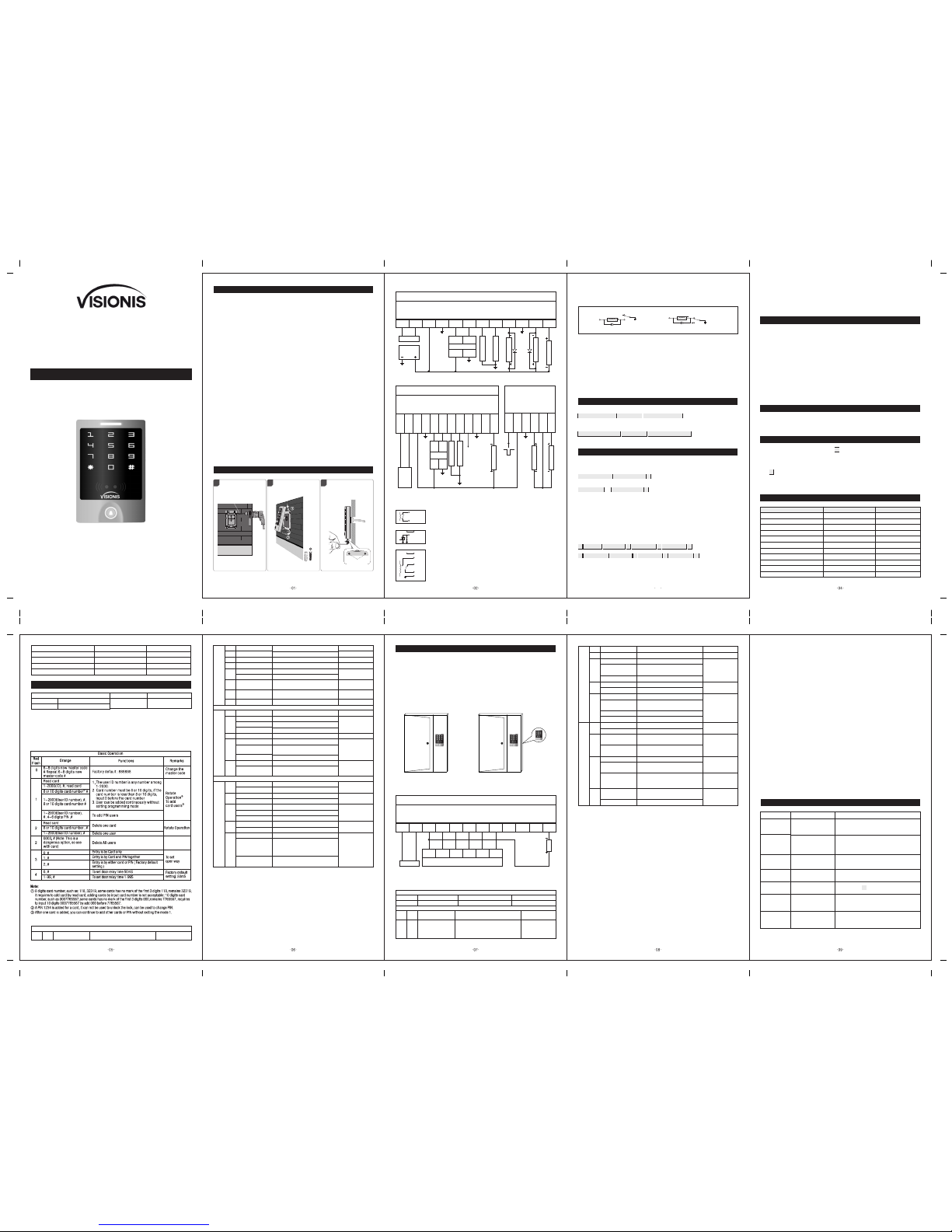
2. Insta llati on and Wi ring Di agram
Wiring D iagra m
VIS-30 00 Sing le door (DC pow er supp ly )
BELL_A
BELL_B
+12V
GNDD0D1
D_in(L ED)
OPEN(B Z)NOCOM
NC
ALARM-
DoorBel l
Red
Black
Black
Green
WhiteRed
Brown
Yellow blue
Purple
Orange Gray
Alarm
DoorCon tact
ExitBut ton
Pink
Light
green
Reader
Stand alone A ccess C ontro l
Green
White
LockB
LockA
DC 12V
Power
BELL_A
BELL_B
Princi ple of Do or Bell C onnec tor
Each pre ss of doo r bell bu tton, co ntact o f relay i n BELL_ A and BEL L_B wil l
close co ntact f or 200m S then re lease .
+12V +12V
ALARM-
Princi ple of Al arm Con necto r
The fiel d-eff ect tub e will be c onduc ted whe n alarm i s activ ated; I t will be n ot
conduc ted whe n alarm i s remov ed
+12V +12V
NO
NC
COM
GND
Princi ple of El ectro nic Loc k
The rela y will cl ose con tact to u nlock t he lock a nd will r eleas e after u nlock ing
COM: com mon, rel ay cont act
NC: norm al clos e, norma lly kee p closed t o COM
NO: norm al open , normal ly keep o pened t o COM
VIS-30 00 Sing le door ( Speci al acce ss cont rol pow er supp ly )
BELL_A
BELL_B
+12V
GNDD0D1
D_in(L ED)
OPEN(B Z)NOCOM
NC
ALARM-
PUSH
+12V
GNDNOCOM
NC
50mS
Door
Bell
Green
White
Red
Black
Black
Green
White
Red
Brown
Yellow
blue
Purple
Orange
Gray
Alarm
DoorCon tact
ExitBut ton
LockB
LockA
Pink
Light gr een
Reader
Acces s Contr ol
Power Su pply
Stand alone A ccess C ontro l
Factory
default 0(50mS)
PUSH
4.7 Door B ell
Press th e door be ll butt on on the a ccess c ontro l unit, th e buzze r will so und rin g back to ne, at th e same
time, the I b ox's bu ilt-i n door be ll or the o uter do or bell w ill rin g.
Remark : When th e work mo de is set i n Auto Mo de (Fac tory De fault Mo de), th ere wil l be no rin g
back ton e witho ut the I Bo x.
5.1 Anti Tamper Alarm
When the acce ss control u nit is disas sembled i llegall y, the access con trol unit' s buzzer and t he externa l
alarm will op erate.
5. Alarm
5.2 Door Stat us Switch
When connec t with door st atus swit ch, if the door is o pened ille gal, the acce ss contro l unit's buz zer and
the externa l alarm will o perate.
5.3 Anti-dur ess alarm
When read zon e 1 duress car d / input 8digi ts duress PI N OR zone 2 dure ss card / input 8 digits du ress PIN,
then press #, the c orrespo nding lock w ill open, at th e same time, th e external a larm will op erate, but th e
access cont rol unit' s buzzer wil l not operat e.
5.4 To remove the ala rm
Read valid ca rd or input ma ster code ca n remove the al arm. If there i s no operati on, the alarm w ill remov e
automati cally aft er 1 minute.
Keypad acce ss contro l, power off, ke ep pressin g * and power on , the logo will tu rn in orange a fter 1
second, rele ase it until h earing two s hot beep , then he aring a long b eep, enter no rmal mode, re set to
factory de fault sett ing is succe ssfully.
Touch panel acc ess contro l (VIS-30 00) ,powe r off, power on, th e logo will tu rn in orange af ter 1 secon d,
press * withi n 1 second, rel ease it unti l hearing tw o shot beep, the n hearing a lo ng beep, ente r
normal mode , reset to fact ory defau lt setting i s success fully.
Remark: Rese t to factor y default, th e users' inf ormatio n is still ret ained.
7. To Reset to F actor y Defau lt
3.1 Add user card( s)(In d ual doo r mode, us ers can b e only ad ded to zo ne 1)
Read man ager ad d card Re ad User card Re ad mana ger add c ard
Cards ca n be adde d conti nuous ly.
3.2 Dele te user c ard(s )
Rea d manag er dele te card R ead Use r card Re ad mana ger del ete car d
Cards ca n be dele ted con tinuo usly.
3 . Ma nager C ards Op erati on
4. User Op erati on
4.1 To unloc k the loc k by one ca rd: Read v alid ca rd once , the lock w ill be un locke d.
4.2 To unloc k the loc k for car d and PIN u sers
Read val id card o nce Inp ut 4-6 di gits PI N # , the lock w ill be un locke d.
4.3 To unloc k the loc k for car d or PIN us ers
Read val id card O r Input 4 -6 digi ts PIN # , the l ock wil l be unlo cked
4.4 To unloc k the loc k for mul ti card s: Read 2- 10pcs v alid ca rds (ti me inte rval ca n not exc eed 5s) , the
lock wil l be unlo cked.
Precon ditio n: Set the d oor ent ry by ca rd only, an d set “2-1 0”for o penin g the doo r by mult i cards
4.5 Toggle M ode
In norma l mode, Ev ery ti me a vali d card/ tag rea d or PIN in put, the r eplay w ill ope rate, fo r the pre -set
replay p ulse ti me.
Every ti me a vali d card/ tag re ad or PIN i nput in Togg le mode , the rela y chang es sta te, whic h will no t
turn bac k until r ead car d/tag o r input P IN agai n.
4.6 To change the PIN o f a PIN use r
Read car d Input o ld PIN # In put new P IN # Inpu t new PIN #
Or
User ID nu mber In put old P IN # Inpu t new PIN # I nput ne w PIN #
Remark :
For user s witho ut card , must get I D numbe r and ini tial PI N from th e maste r. For Zone 1, th e first d igit of
PIN must b e “1”, for Zo ne 2, the f irst di git of PI N must be “2 ” For the ca rd user s with PI N “1234” , must
use Read ing car d to chan ge the PI N for the f irst ti me.
*
*
8. Sound a nd Ligh t Indic ation
Operat ion Sta tus
Standb y
Press Ke y
Read Car d
Unlock t he lock
Operat ion Suc cessf ul
Operat ion Fai led
PIN Inpu tting
Card & PIN R eadin g
Multi Ca rd Read ing
1 M enu
2 Menu
Logo Col or
White
Green
Slow Fla sh Red
Green
Green
Slow Fla sh Red
Slow Fla sh Red
Slow Fla sh Red
Slow Fla sh Oran ge
Buzzer
Short Ri ng
Long Rin g
Long Rin g
Long Rin g
3 Short Ri ng
Under Se tting
Manage r Card Re ading
Manage r Card Ex it
Alarm
Ring-b ack Tone
Orange
White
Quick Sh ine in Re d
Orange
2 Short Ri ng
Long Rin g
Alarm
Ding-D ong
st
nd
Logo LED L ight in dicat ion
Remark s
Factor y defau lt :
888888
Functi ons
To enter the
progra mming m ode
White lo go
*
6-8 digi ts Mast er code #
Red logo L ED flas h
Enter Mas ter Ope ration M ode. It wi ll retur n to norm al mode if t here is no r ight Mas ter PIN i nput in 5
seconds . After inp ut of righ t maste r PIN, it wil l also ret urn to no rmal mod e if there i s no vali d operat ion
in 30 secon ds. Pres s “#” to confi rm the in put numb er, return t o previo us menu by p ress “*” , the logo
light wil l indic ate the op erati on mode.
Note that t o under take the f ollowi ng prog rammin g, the mas ter user m ust be log ged in
9. Maste r Setti ng
03
To prevent cons ecutive en ter of an inva lid master c ode, user pas sword, or ant i-dures s or invalid c ard,
this functi on will be act ivated af ter 10 times c onsecuti ve errors i nput. There ar e 3 mode avail able:
No keypad loc kout or alar m, keypad loc ked for 10 min utes, alarm f or 1-3 minut es.
6. Keypa d locko ut or ala rm
9.2 Advan ced ope ratio n:
Remark sFuncti ons
Red
Flash
Orange
Advanc ed Appli cati on
Orange
Flash
Remark:
① Every time a valid card/tag read or PIN input in in Toggle mode, the relay changes state, which will not turn
back until read card/tag or input PIN again.
②The door will open only when read the valid card quantity up to the quantity set. It is only for Card Only mode.
③ The card number must be consecutive, Card quantity is between 1-2000.
④ After unlocking, enter the normal working state.
⑤ After closed the alarm, anti tamper, anti-duress and door magnetic alarm are invalid.
⑥ Refers to static state, normal indication according to operation.
⑦ Enter the administrator password correctly, the buzzer alarm in the normal phonation.
⑧ Each key press or read card, keypad backlight will light 30S delay after the close, in close state , the first key
is just to start the keyboard light, no an y function.
⑨ 10 times consecutive errors including: enter an invalid master code, user password, or anti-duress or invalid
card.
10. Vari ous Work ing Mod es Appl icati on
The device has 3 working modes:
1. Wiegand Reader
2. Standalone for single door (Factor y default setting)
3. Anti-pass back for single door
Through Wiegand data lines , can make the device and external card reader are connected together, to realize
of various functions.
Card number and PIN etc information will store in the device.
The external reader only read card or as a device for input PIN, you can connect with a numbers of readers , but
function all same.
Access
Host
External Reader
(Inside Door)
(Outside Door)
Access
Host
(Outside Door)
Standalone for single door
Anti-pass back for single door
10.1 Wieg and Rea der Mod e
VIS-3000 Reader Wiring Dragram
BELL_A
BELL_B
+12V
GNDD0D1
D_in(L ED)
OPEN(B Z)NOCOM
NC
ALARM-
DoorBel l
Black
Green
WhiteRed
Brown
Yellow blue
Purple
Orange Gray
Alarm
Pink
Light
green
CNDD0D1+12V LED BZ
Commo n Acces s Contr ol
Stand alone A ccess C ontro l ( Reade r Mode)
In this mode, the access host works as reader, it can be done below settings.
Remark sFuncti ons
Red
Flash
Orange
Orange
Flash
Admini strat or Sett ing
Remark s
Factor y defau lt :888 888
Functi ons
Enter pr ogram ming mo de
White
*
6-8 digit s Master c ode #
Red flas h
Reader S ettin g
6~8 digits new master
code # Repeat 6~8
digits new master code
#
Factory defa ult : 888888
Change the mast er
code
0
10.3 Anti-passback for Single Door
> In this mode, access host install outside is for entering door, external reader inside for exiting door, they build
up a single door anti-passback system, access host is the anti-passback master unit.
> Read valid card or input PIN on access host, door will open; read valid card or input PIN on external reader,
door will open.
> When input duress PIN/Card, the door will open, at the same time, the external alarm operates
> When input duress PIN/Card on external reader, the door will open, at the same time, the external alarm
operates.
> Open type forced Card Only, the user PIN is invalid.
> The users can only enter door when read valid card on access host, and exit from the inside external reader,
If without the entering record from access host, the users can not exit from the inside reader, also the users
can't enter in twice without the first exit record.
Cannot enter
Administrator
setting mode
Forget master code
For othe r issue s beyon d above , welcom e to cont act our t echni cians f or more d etail s.
Reset to Factory Default, default master code is 888888,
need to reset conditions and specifications, but users'
information is still retained
Fault Phenomenon
Fault Cause
Reading distance
is too close
1. Card problem
2. Switch power supply
interferences card reading
Set user PIN failed
1. Wrong way of PIN setting
2. Setting PIN under card
reading mode
Can’t open door
after inputting
user's PIN
Use 1234 as user's PIN
Alarm under
normal situation
Light leaking when install
access host
No reaction when
reading card
not on standby status
Reason & Solution
1. Please use original made card
2. Wiring power supply and access host shell to ground
wire
1. In mode of two Doors 1,the 1st digit of PIN must be 1.
Two doors 2, the 1st digit of PIN must be 2.
2. User PIN cannot be 1234
3. User PIN only can be 4~6 digits
1234 is the initial value, can't be used to open doors,
unless after resetting them to other 4~6 digits
Leaning on wall closely when install access host
Exit by pressing * until logo light turns to white
1. Set the keypad light to always On or automatic mode
2. Under automatic mode, keypad light will on when
people approaching
Keypad light off
Set keypad light mode
improperly
11. Simp le Troubl eshoo ting
Factory defa ult setting : 0
0-15, #
To set facility code
Factory defa ult setting :26
4-6 digis key pres s sends card num ber
Each key press sen ds 4 bit output da ta
(Factory def ault settin g)
Each key press sen ds 8 bit output da ta
Close Alarm
Alam time is 0-3 min utes for optio n
No door bell funct ion
Built-in doo r bell- ON (Facto ry default
setting)
External doo r bell-ON
Built-in & exte rnal door bel l - ON
To set Wiegand format
To set keypad
transmissi on format
To set Alarm
To set door bell
function
26-37, #
0, #
2, #
1, #
2
3
0
0, #
1-3, #
4
0, #
1, #
2, #
3, #
5
7
When LED level is low, logo light will turn into Green, after 30 seconds or LED level rising, Logo light will back to
normal.
When BZ level is low, the Buzzer will beep, after 30 seconds or BZ level rising, the Buzzer will back to normal.
When the access host worked as reader, both card number and keypad transmits in Wiegand format, the output
data are shown by the Low Level of D0 & D1 cable:
D0: Low level means 0, green cable
D1: Low Level means 1, white cable
The Pulse Width of Low level is 40uS, Bit period is 2mS.
The digit of Car number can be set to 26~27Bit, should be matched with the controller. (Factory default is 26Bit)
Wiegand 26 card reader, HID card can output Wiegand 26~37 automatically, other cards are output Wiegand 26
compulsively.
Wiegand 27~37 card reader, all cards are forced output Wiegand 27~37.
Keypad transmission can be set in the following 3 modes
Disable
Enable(Fac tory defaul t setting)
OFF-The devi ce will be in silen ce
except enter th e programmi ng mode
ON-The devic e will give the voi ce when
press the keys (Fa ctory defau lt setting )
Disable keyp ad backligh t
Enable keypa d backlight (Fa ctory
default sett ing)
To set logo LED light
To set keypad tone
ON or OFF
To set keypad
backlight
0, #
1, #
0, #
1, #
0, #
1, #
2
3
1
8
Automatic mo de
Normally it is off (sleepin g mode) but
wake up with human a pproach
Disable anti ta mper alarm ( Fact ory
default sett ing )
Enable anti tam per alarm
To set anti tamper
alarm
0, #
1, #
2, #
4
To set keypad
backlight
Model 0: The Reader will transmit the PIN data when it receives the last key (#) press after PIN code
Format: Decimal card number with 10-digit , Facility Code(1st ~ 4th digit)+ PIN Code (5th ~ 10th digit)
(Facility code is any digits between 0~15, PIN code is 4~6 digits)
Example: Facility code:15
PIN code: 2999
Press 2999 #, then output format will be: 0015002999
PIN code: 999999
Press 999999#, then output format will be 0015999999
9.1 Basi c Opera tion
( Factory default setting: 26 )
4-6 digis key press sends card number
Each key press sends 4 bit output data
( Factory default )
Each key press sends 8 bit output data
To set Wiegand format
To set keypad
transmission format
2
3
7
26-37, #
0, #
1, #
2, #
Close Alarm⑤
Alarm time is 0-3 minutes for option
( Factory default 1 minute )
To set Alarm
4
Opeion al Sett ing
Indicator light OFF⑥
Indicator light ON ( Factory default )
Disable buzzer ⑦
Enable buzzer ( Factory default )
Disable keypad backlight
Enable keypad backlight ( Factory default )
Auto mode⑧
Disable anti tamper alarm ( Factory default )
Enable anti tamper alarm
No keypad lockout or alarm (Factory default)
In 10 minutes, if there's 10 times⑨invalid
card or wrong password, the device will lock
on for 10 minutes.
In 10 minutes, if there's 10 times invalid card
or wrong password, the device will alarm.
To set logo LED light
0, #
1-3, #
0, #
1, #
1
0, #
1, #
2
0, #
1, #
3
2, #
0, #
1, #
4
0, #
1, #
5
2, #
8
Read card
Set add card
To add card user
1
6
Set delete card
To set duress users
To delete card user
To set duress user
Read card
Read card
8 digits duress PIN,#
To set duress PIN To set duress PIN
Automatic mode Factory default ( )
Set Zone 1as Auto-lock switch①
Factory default setting :1
To set open door by
multi cards②
Relay setting
The card number must be consecutive
Card quantity is between 1-2000
User ID number # card
number # card quantity #
To add a series cards
users. ③
0, #
1, #
1-10, #
Administrator open door 1
Exit automatic④
1
2
3
4
5
6
7
9
System Setting
Factory default setting: 0
Wiegand reader mode
Standalone for single door Factory default ( )
Anti-passback for single door
To set facility code
To set working mode
1
0
1-15, #
0, #
1, #
5, #
Model1: 4-Bit
The output data is provided in following format after every key is pressed:
1(0001),2(0010),3(0011)
4(0100),5(0101),6(0110)
7(0111),8(1000),9(1001)
*(1010),0(0000),#(1011)
Model 2: 8-Bit
The output data is transmitted in following format after every key is pressed:
1(11100001),2(11010010),3(11000011)
4(10110100),5(10100101),6(10010110)
7(10000111),8(01111000),9(01101001)
*(01011010),0(11110000),#(01001011)
10.2 Standalone for Single door
In this mode, the access host uses can open the door by valid card or PIN, it supports connecting external card
reader for exiting door.
When input duress PIN/Card, the door will open, at the same time, the external alarm operates
3
Fix Safe Sc rews
1
Product Bracket Size: 72.8 X 115.9mm
Sticker Size: 78 X 121mm
Diameter: 6mm(Rubber Bungs)
60.60 mm
81.80 mm
25.29 mm
Diameter: 2mm
Diameter: 30mm
For concrete wa ll, dri ll the ho le in 6mm d iamet er
Drill Hol es
2
Pay attentio n to the se quenc e durin g insta llati on
Fix the Bra cket an d
Install t he Acce ss Host
Safe Screw s
VIS-30 00 Inst allat ion
VIS-3000
Sta ndalo ne Acce ss Cont rol Key /Read er
 Loading...