

Page 1
DE2460U 1
MCM
MCMMCM
MCM-140
-140-140
-140
Wireless Remote Commander
User’s Guide
1111. INTRODUCTION
. INTRODUCTION. INTRODUCTION
. INTRODUCTION
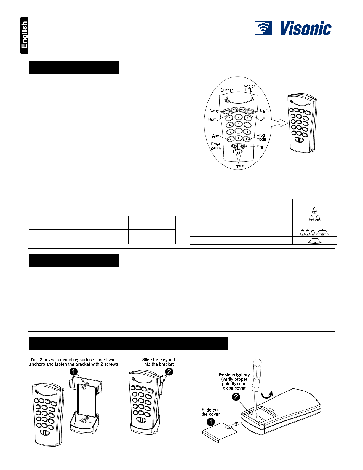
The MCM-140 is a wireless remote control unit for the PowerMax
system. It enables the user to arm/disarm the alarm system, to
initiate emergency/fire/panic alarms, to perform one of the AUX
(auxiliary) functions (see Note 3 in Section 6) and to turn lighting
devices on and off. The keypad includes an RF transmitter that
sends out a differently coded RF signal for each command.
The main features of the MCM-140 are:
• Automatic reporting of low battery voltage.
• Visual indications by red/green/amber LED.
• Keypad back lighting (selectable)
• Various audible signals sounded by the buzzer in response to
specific actions.
• Automatic supervision messages at 60 minute intervals or
according to the local standards.
• Long-life 3 VDC lithium battery.
• Wall mounting option.
• Friendly programming.
The red LED lights during transmission. The amber LED lights
during the programming process (and during transmission if battery
voltage is low). The green LED lights upon each keystroke.
LED Indications
Description Symbol
Blinks at a fast rate - - - - - - Blinks at a slow rate _ _ _ _ _
Lights steadily (during transmission) ________
Figure 1 - External View
Keypad Buzzer Sound
Description Symbol
Short single beep, upon pressing a key
2 short beeps, in the programming process
(par. 4.3 & 4.5)
Success (victory) melody
Failure beep
2222. SPECIFICATIONS
. SPECIFICATIONS. SPECIFICATIONS
. SPECIFICATIONS
Transmitted ID Type: PowerCode and CodeSecure
PowerCode - Used for Lights 1-7, Light 8 (PGM controlled),
Fire and Emergency functions
CodeSecure - Used for Home arming, Away arming,
Disarming, Aux and Panic functions
Operating Frequency (MHz): 315, 433.9 and 868.95
Battery: 3 VDC, Lithium battery, CR123A
Current Consumption: 10 µA approx. (STBY), 95 mA (in
transmission, including LED and back light currents)
Battery Life Expectancy: 3 years (for typical use)
Back light illumination: Selectable on/off
Dimensions (HxWxD): 127 x 70 x 24 mm (5 x 2-3/4 x 31/32 in.)
Operating Temperatures: 0°-49°C (32°-120°F)
Compliance with Standards: FCC part 15,
IC:1467102181.
The term "IC" before the certification/registration number
only signifies that the Industry Canada technical
specifications were met.
3333. MOUNTING AND BATTERY REPLACEMENT
. MOUNTING AND BATTERY REPLACEMENT. MOUNTING AND BATTERY REPLACEMENT
. MOUNTING AND BATTERY REPLACEMENT
Figure 2 - Mounting Figure 3 - Battery Replacement
Page 2
2 DE2460U
4444. PROGRAMMING
. PROGRAMMING. PROGRAMMING
. PROGRAMMING
4.1 Programming Scope
The following programming actions are possible:
• Setting the master user (user #1) code.
• Setting other user codes (users #2-8).
• Allowing/forbidding quick arming of the keypad.
• Muting/reactivating the keypad's buzzer.
• Controlling the keypad's back-lighting.
• Enabling/disabling the supervision/low battery reporting from
the MCM-140.
4.2 Entering the Programming Mode
The programming mode is accessible with the master code only
(1 1 1 1 by default). The "#" key is used to enter and also to exit
the programming mode.
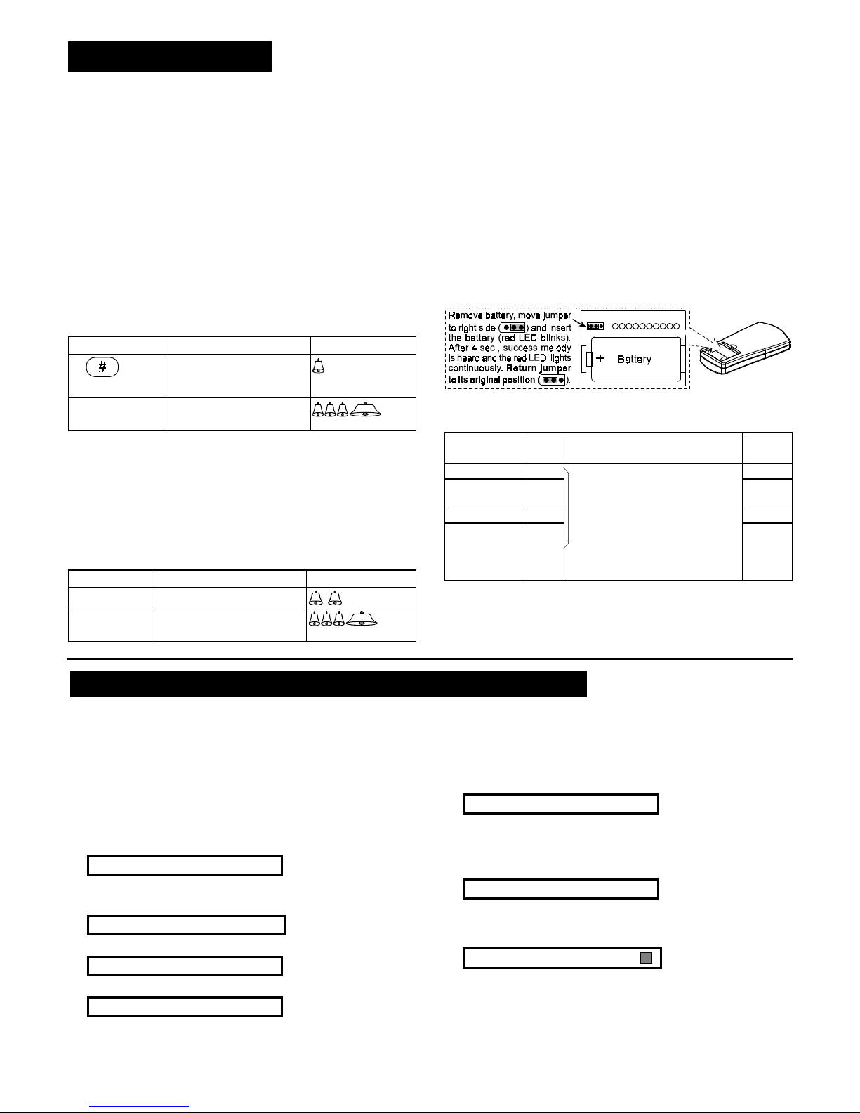
Entering the Programming Mode
Action LED indication Buzzer response
Green LED blinks slowly
until the master code is
keyed *
[master code]
(1111 by default)
Amber LED blinks slowly
during programming *
(success melody)
* Upon entering the programming mode, the success melody is
heard and the amber LED starts blinking. Blinking will stop
once you exit from this mode (by pressing "#" again) or upon
time out during which no key is pressed. 2 short beeps are
heard when the LED stops blinking.
4.3 Changing Master/User Codes
To change the MCM-140 master and user codes, enter the
programming mode (Par. 4.2) and proceed as follows:
Action LED indication Buzzer response
[1-8]
1
Amber LED blinks
[new code]
2
Amber LED blinks quickly (blinks slowly after success)
(success melody)
Notes
1. Enter user No. (1-8). User No. 1 is defined as the master user.
2. Master/user codes consist of 4-digits. Code "0000" is not
valid. It can be used to erase the currently programmed code
(when this action is performed, success melody is heard).
3. PowerMax user codes and MCM-140 user codes are different
codes.
4.4 Restoring the Default Master Code
If the master code is forgotten, it is possible to recall the factory
default master code "1111". To ensure that this possibility is
not misused by unauthorized people, a panic alarm is
automatically transmitted to the PowerMax system when
such an action is performed.
To recall the default master code and prevent a panic alarm, set
PowerMax to User Settings mode (see PowerMax Prog. Guide,
Par. 1.2) and proceed as shown in the following illustration:
4.5 Special Programming Options
Enter the programming mode (Par. 4.2) and proceed as follows:
Desired
function
Press and then press: Default
Quick arming 9 ➔ 1OFF
Buzzer control 9 ➔ 2 AWAY to enable (amber LED
lights)
ON
Back lighting 9 ➔ 3 OFF to disable (amber LED blinks). ON
Supervision / low
battery reporting
(only by using
Fire button)
9 ➔ 4 In both cases, the buzzer sounds
twice, to indicate success.
OFF
Notes:
1 . The supervision message will be sent once an hour or
according to local standards.
2 . When there is Low Bat condition, trouble message will be
displayed for the zone that was selected for the FIRE key.
5555. ENROLLING THE MCM
. ENROLLING THE MCM. ENROLLING THE MCM
. ENROLLING THE MCM-140
-140-140
-140 TO THE POWERMAX
TO THE POWERMAX TO THE POWERMAX
TO THE POWERMAX
5.1 Enrolling Arming, Disarming, Aux
and Panic Functions
To enroll the MCM-140 keyfob functions (Home/Away arming,
Disarming, Aux and Panic functions), proceed as follows:
A. Enter PowerMax installer menu (see PowerMax Programming
Guide, document DE5450P, par. 1.2).
The PowerMax display will be "1. NEW INSTL CODE".
B. Click <NEXT>. The enrolling mode will be selected and the
PowerMax display will show:
2. ENROLLING
C. Click <OK>.
The PowerMax display will change to:
ENROLL WL DEVICE
D. Click <NEXT>. The PowerMax display will read:
ENROLL KEYFOB
E. Click <OK>. The PowerMax display will read:
Keyfob No: _
F. Press the key on the PowerMax keypad that corresponds with
the location (1-8) that you wish to enroll in.
Note: If you are using the latchkey feature, and keyfob
locations (5-8) are programmed with an MCM-140, then all
disarming actions performed by the MCM-140 will be
considered latchkey disarming.
If, for example, you have pressed the "1" key of the PowerMax
keypad, the PowerMax display will change to:
Keyfob No: 1
The clear space at the far right tells you that the memory
location is free.
G. Click <OK>. The PowerMax display will prompt you to initiate
a transmission from the MCM-140:
TRANSMIT NOW
H. Initiate a transmission from the MCM-140 by pressing the "∗"
button for 2 sec. approximately. As a result, the “Happy Tune”
(- - - –––) will sound and the PowerMax display will change to:
Keyfob No: 1
A dark box will appear at the far right, indicating that the
chosen function has been enrolled.
Note: If the same function is already enrolled elsewhere, the
“Happy Tune” will sound twice in succession.
Page 3
DE2460U 3
5.2 Enrolling Lights, Fire, and
Emergency Functions
The following MCM-140 PowerCode control functions can be
enrolled:
•
X-10 devices ( 1-7)
• PGM output (activated by
).
• Fire
• Emergency
To enroll these functions, proceed as follows:
A. Enter PowerMax installer menu (see PowerMax Programming
Guide, document DE5450P, par. 1.2). The PowerMax display
will be "1. NEW INSTL CODE".
B. Click <NEXT>. The enrolling mode will be selected and the
PowerMax display will show:
2. ENROLLING
C. Click <OK>. The PowerMax display will change to:
ENROLL WL DEVICE
D. Click <OK> again. The PowerMax display will read:
Zone No :
_
_
E. From the PowerMax keypad, enter the number of the zone to
which you wish to enroll your first X-10 device. For instance, if
you enter <2> Ö <3>, the PowerMax display will change to:
Zone No: 23
The clear space at the far right tells you that the zone is free no device has been enrolled to it as yet.
F. Click <OK>. The PowerMax display will prompt you to initiate
a transmission from the chosen wireless device:
TRANSMIT NOW
G. Initiate transmission from the MCM-140 by pressing the
LIGHT key followed by pressing "1" (for X-10 device #1).
H. In response to the transmitted signal, the “Happy Tune”
(- - - ––– ) will sound and the PowerMax display changes to:
Zone No: 23
A dark box will appear at the far right, indicating that the
chosen device has been enrolled to Zone No. 23.
I. On the PowerMax, press NEXT button.
J. Perform steps "E" to "H" for the other electrical devices (2 - 8).
K. Perform steps "E" to "H" for the MCM-140 FIRE and
EMERGENCY functions. When you are instructed to transmit,
press the MCM-140 FIRE/EMERGENCY key for 2 seconds
until the RED LED lights and “Happy Tune” (- - - ––– ) sounds.
Notes
1 . There is no need to teach the keypad PANIC function for the
PowerMax - it will be automatically performed.
2 .
Define the zones that are enrolled with X-10 and PGM
devices as "non-alarm" zones, to prevent an alarm display
when the device is activated.
5.3 Programming PGM/X-10 Devices
as "On by Zones"
To enable activation of PGM/X-10 devices from the MCM-140,
they must be programmed as "On by Zones". For the
programming process, refer to the PowerMax programming
guide, section 7 (Defining Output Parameters).
6666. OPERATION
. OPERATION. OPERATION
. OPERATION
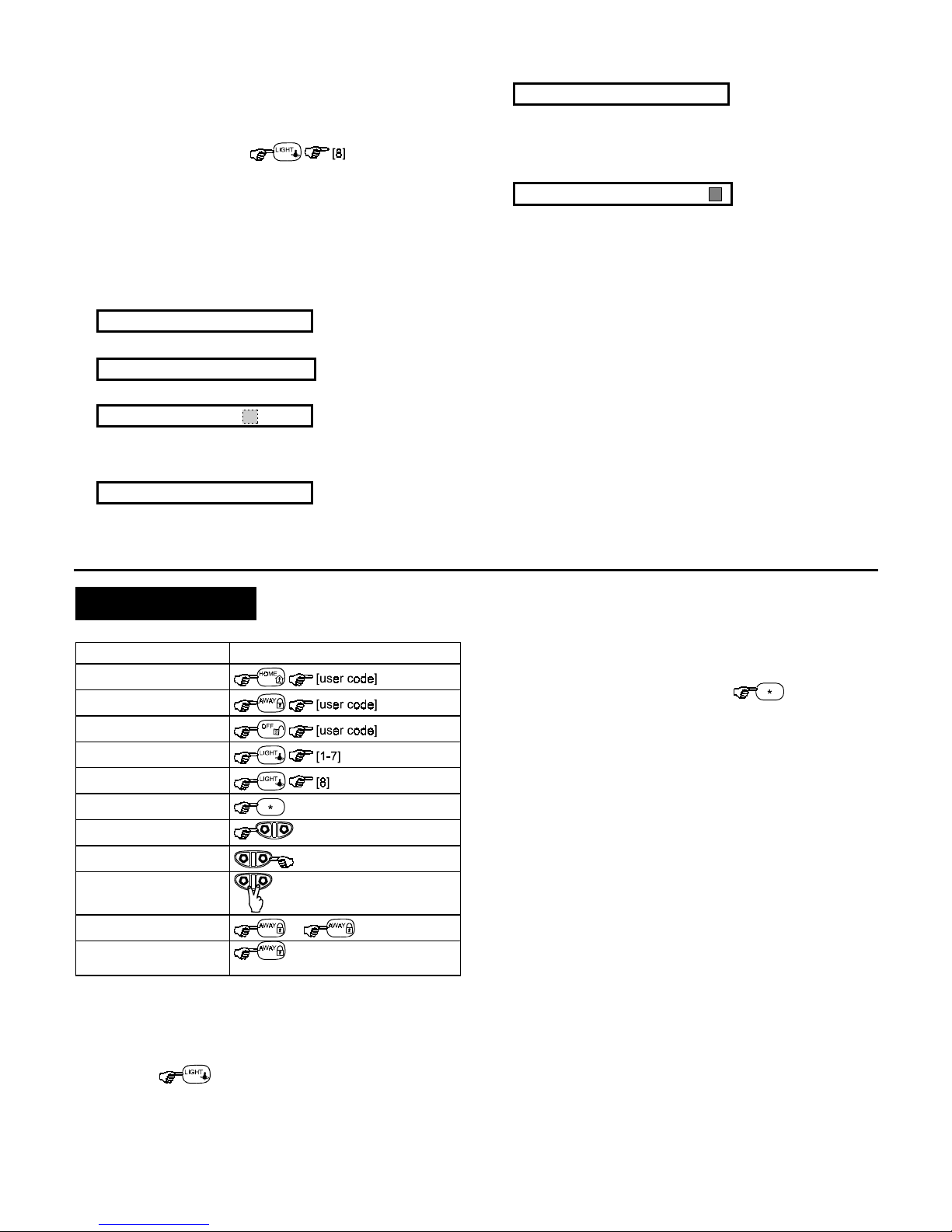
The following table describes how to activate the various functions.
Function Actions
Arming HOME
(1) (8)
Arming AWAY
(8)
Disarming
X-10 device (1-7) On/Off
(2)
PGM output
AUX Function
(≈ 2 sec.)
(3)
Emergency alarm
(≈ 2 sec.)
(7)
Fire alarm
(≈ 2 sec.)
(7)
Panic alarm
(≈ 2 sec.)
(7)
Latchkey arming
....
(4)
Quick arm
(≈ 2 sec.). (LED blinks, then
lights RED during transmission)
Notes
1 . Eight user codes are possible (user code # 1 is the master user
code). Factory default master code is "1111". Upon entering a
valid code or a valid command, the success (victory) melody is
heard and the red LED lights briefly (transmission indication).
2 . Pressing
followed by the desired X-10 device
number (1-7) turns on this device (success beeps are heard).
Performing these actions again turns this device off. In order
for the X-10 device to be turned off when the light key is
pressed the second time, the Toggle mode must be selected.
This can be selected in the "PGM/X-10 Time" under "4.
Define Panel" in the installer mode (refer to the PowerMax
programming guide, par. 5.20).
3 . The AUX function works just like the [
∗
] key in the keyfob.
Pressing the Auxiliary Function key
(≈ 2 sec.) can
initiate the STATUS action (system status announcement),
the INSTANT action (entry delay cancellation) or the PGM
action (activation of PGM output or X-10 units), depending on
prior installer programming. For selecting the desired auxiliary
function, refer to the PowerMax Programming manual, Para.
5.16 (AUX Button).
4 . For LATCHKEY arming function, press the AWAY key, wait
until the red LED extinguishes, then press the AWAY key
again. The red LED lights and extinguishes again.
From PowerMax version V1.16: For Latchkey disarming, the
MCM-140 can be learned into the PowerMax as user 5, 6, 7
or 8. You can use the MCM code 1, 2, 3, 4, 5, 6, 7, or 8.
5 . Pressing a non-valid code combination (not master / user
code) causes a long failure beep.
6 . If a keying sequence is not completed within timeout, the
desired function will not be executed.
7 . Pressing the Emergency, Fire or Panic buttons, causes the
red and green LEDs to blink alternately for 2 seconds to alert
the user. The red LED lights during transmission. The
PowerMax panic function can be programmed (enabled or
disabled) by the installer.
8 . If arming Home or arming AWAY command is used with an
invalid user code, the command will not be performed. To enter
the arming HOME/AWAY command again, you have 2 choices:
a. Wait until time out to expire and the green LED stops
blinking. Then try again.
b. Press HOME/AWAY twice, then enter user code again.
Page 4

4 DE2460U
7777. COMPLIANCE WITH STANDARDS
. COMPLIANCE WITH STANDARDS. COMPLIANCE WITH STANDARDS
. COMPLIANCE WITH STANDARDS
This device complies with the essential requirements and provisions of
Directive 1999/5/EC of the European Parliament and of the Council of
9 March 1999 on radio and telecommunications terminal equipment.
Frequency Allocations for Wireless Devices in
European Countries:
• 433.92 MHz has no restriction in any EU member state.
• 315 MHz is not allowed in any EU member state.
• 868.95 MHz (wide band) is allowed in all EU member states.
• 869.2625 MHz (narrow band) is not restricted in any EU
member state.
The user is cautioned that changes or modifications to the unit,
not expressly approved by Visonic Ltd., could void the user's FCC
or other authority to operate the equipment.
The 315 MHz model of this device complies with Part 15 of the
FCC Rules and RSS-210 of Industry and Science Canada.
Operation is subject to these two conditions: (1) This device may
not cause harmful interference, and (2) this device must accept
any interference received, including interference that may cause
undesirable operation.
WARRANTY
WARRANTYWARRANTY
WARRANTY
Visonic Ltd. and/or its subsidiaries and its affiliates ("the Manufacturer") warrants its
products hereinafter referred to as "the Product" or "Products" to be in conformance with
its own plans and specifications and to be free of defects in materials and workmanship
under normal use and service for a period of twelve months from the date of shipment by
the Manufacturer. The Manufacturer's obligations shall be limited within the warranty
period, at its option, to repair or replace the product or any part thereof. The Manufacturer
shall not be responsible for dismantling and/or reinstallation charges. To exercise the
warranty the product must be returned to the Manufacturer freight prepaid and insured.
This warranty does not apply in the following cases: improper installation, misuse,
failure to follow installation and operating instructions, alteration, abuse, accident or
tampering, and repair by anyone other than the Manufacturer.
This warranty is exclusive and expressly in lieu of all other warranties, obligations or
liabilities, whether written, oral, express or implied, including any warranty of
merchantability or fitness for a particular purpose, or otherwise. In no case shall the
Manufacturer be liable to anyone for any consequential or incidental damages for breach
of this warranty or any other warranties whatsoever, as aforesaid.
This warranty shall not be modified, varied or extended, and the Manufacturer does not
authorize any person to act on its behalf in the modification, variation or extension of this
warranty. This warranty shall apply to the Product only. All products, accessories or
attachments of others used in conjunction with the Product, including batteries, shall be
covered solely by their own warranty, if any. The Manufacturer shall not be liable for any
damage or loss whatsoever, whether directly, indirectly, incidentally, consequentially or
otherwise, caused by the malfunction of the Product due to products, accessories, or
attachments of others, including batteries, used in conjunction with the Products.
The Manufacturer does not represent that its Product may not be compromised and/or
circumvented, or that the Product will prevent any death, personal and/or bodily injury
and/or damage to property resulting from burglary, robbery, fire or otherwise, or that the
Product will in all cases provide adequate warning or protection. User understands that a
properly installed and maintained alarm may only reduce the risk of events such as
burglary, robbery, and fire without warning, but it is not insurance or a guarantee that
such will not occur or that there will be no death, personal damage and/or damage to
property as a result.
The Manufacturer shall have no liability for any death, personal and/or bodily injury
and/or damage to property or other loss whether direct, indirect, incidental,
consequential or otherwise, based on a claim that the Product failed to function.
However, if the Manufacturer is held liable, whether directly or indirectly, for any loss or
damage arising under this limited warranty or otherwise, regardless of cause or origin, the
Manufacturer's maximum liability shall not in any case exceed the purchase price of the
Product, which shall be fixed as liquidated damages and not as a penalty, and shall be
the complete and exclusive remedy against the Manufacturer.
Warning: The user should follow the installation and operation instructions and among
other things test the Product and the whole system at least once a week. For various
reasons, including, but not limited to, changes in environmental conditions, electric or
electronic disruptions and tampering, the Product may not perform as expected. The user
is advised to take all necessary precautions for his /her safety and the protection of
his/her property.
6/91
VISONIC LTD. (ISRAEL): P.O.B 22020 TEL-AVIV 61220 ISRAEL. PHONE: (972-3) 645-6789, FAX: (972-3) 645-6788
VISONIC INC. (U.S.A.): 10 NORTHWOOD DRIVE, BLOOMFIELD CT. 06002-1911. PHONE: (860) 243-0833, (800) 223-0020. FAX: (860) 242-8094
VISONIC LTD. (UK): FRASER ROAD, PRIORY BUSINESS PARK, BEDFORD MK44 3WH. PHONE: (0870) 730-0800 FAX: (0870) 730-0801
INTERNET:
www.visonic.com
VISONIC LTD. 2002 MCM-140 DE2460U (REV. 2, 9/02)
 Loading...