

Vision Engineering TIM5 User Manual
INSTRUCTIONS
NMM-800RF∕ TRF
SYSTEM METALLURGICAL
MICROSCOPE
TIM5 User Guide
Material Inspection Microscope

1
Contents
USER NOTICE 2
1. Components 3
2. Assembly 4
3. Operation 9
4. Observation Methods 16
5. Troubleshooting 18

2
User Notices
I. Safety note
i. When unpacking, please take care not to drop fragile items, such as lenses.
ii. Keep the instrument out of direct sunlight; avoid high temperatures or humidity, dusty environments. Make sure the work
surface is stable and away from sources of vibration.
iii. Take care when moving the instrument, using two hands to grip with the sides of the microscope body.
iv. Caution! The lamp house and nearby parts will be very hot during operation. Ensure sufficient space to allow cooling.
v. Before replacing the halogen lamp, or fuse, make sure the main switch is in the “O” (off) position, and turn off the mains
power. Allow the lamp bulb and lamp house completely cool before removal.
vi. Use the factory supplied power cord.
II. Maintenance
i. Do not disassemble any parts of the microscope, as it will affect function, or reduce the performance.
ii. Keep the instrument clean and cover with a dust cover when not in use. Remove dust with a lint-free cloth. Take care to
avoid contaminating the optical elements.
iii. Marks on the prism, such as finger marks or oil should be removed by gently wiped with a piece of lint-free cloth immersed
in pure alcohol or xylene (NOTE: alcohol and xylene are highly flammable. Keep away from heat sources and use them in a
well-ventilated room).
iv. Do not use organic solvent to wipe the non-optical elements.
v. Place the instrument in a cool, dry environment. After using the microscope, cover with a dust cover.
Wait for the lamp house to cool completely before covering.
3
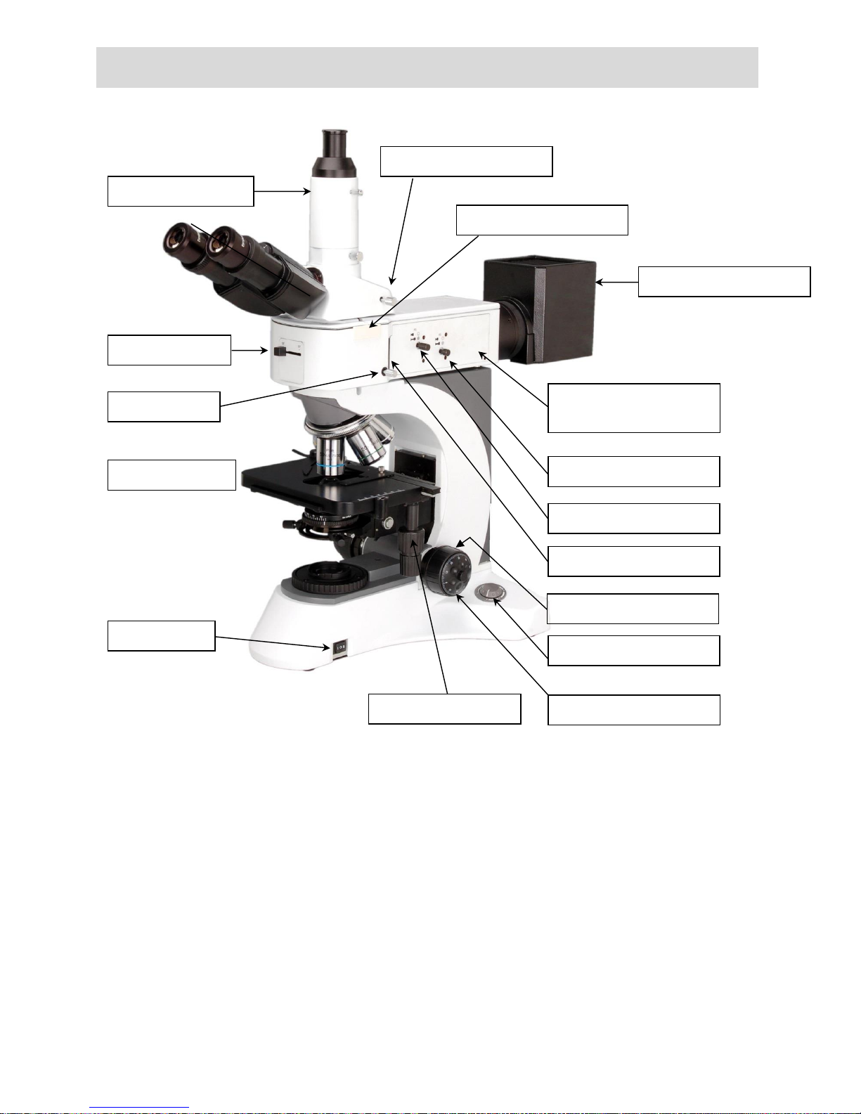
Name of Components
Light path selector lever
Analyser insertion slot
ND filter lever
Polariser insertion slot
Aperture diaphragm lever
Field diaphragm lever
Main switch
Brightness adjustment knob
Right fine focus knob
Mechanical stage
X/Y stage movement
Lamp housing
Trinocular tube
Filter insertion slot
(The filter should be inserted from the left)
Right coarse focus knob
Mirror selector lever
4
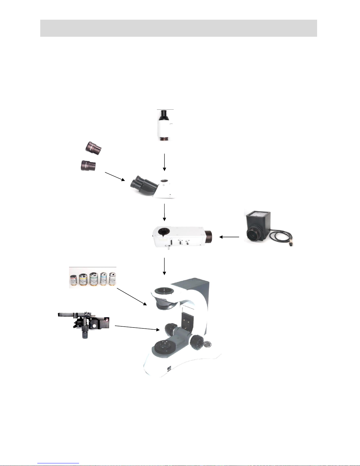
2.Installation
2-1 Installation Diagram
The following figure shows the installation sequence of the components. The number in the figure shows the installation steps.
Before installing, be sure every component remains clean.
Note: The supplied Allen key is required for changing components.
Trinocular tube
Trinocular head
10x wide-field
eyepiece
Lamp
housing
Reflected light brightfield /
darkfield illuminator
Infinity plan objectives
Mechanical stage support
① ⑤ ⑥
③ ⑦ ④
②
5
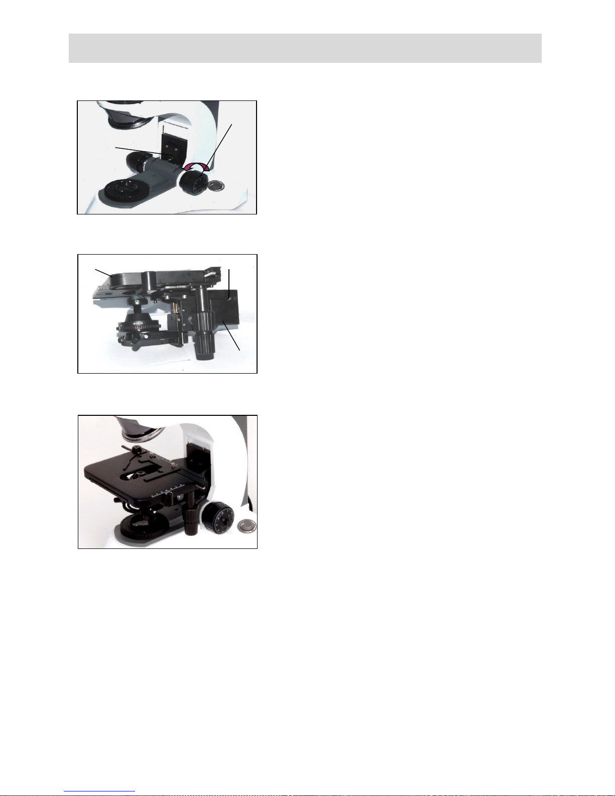
2-2 Installation Steps
2-2-1 Installing the mechanical stage support
Before installing the device, be sure to adjust the coarse focus
control ①. Move the guide board ② down to the lowest
position, so you can install the mechanical stage support device
easily.
Hold on to the mechanical stage support device (Fig.2). Place it
from the top of the guide board (Fig.1), until the stage reaches the
lowest position. Use the Allen key provided to secure the stage
③.
The mechanical stage ⑤ has been adjusted before
leaving factory. Do not disassemble.
Assembled parts should look like Fig.3.
Fig.2
⑤ ③ ④
Fig. 3
Fig.1
②
①
6
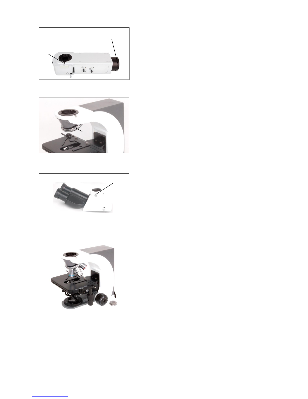
2-2-2 Installing the reflected light brightfield /
darkfield illuminator
Install the reflected light illuminator (Fig.4) on the head of the
microscope body (Fig.5) and then secure the bolt ⑥.
2-2-3 Installing the trinocular head
Insert the video port (Fig.6) into the illuminator (Fig. 4), and then
secure the bolt.
2-2-4 Installing the objective
1. Adjust the coarse focus knob until the support device of the
mechanical stage reaches its lower limit position.
2. Place the lowest magnification objective onto the nosepiece
from the left or the right side and then push the nosepiece
clockwise. Then place other objectives in the sequence of low
to high magnification (Fig.7).
When replacing the objective, slowly turn the
nosepiece until you hear a “click”. The objective will
now be in the required position-(the centre of the
light path).
Fig.5
⑥
Fig.6
⑨
Fig.7
⑦
⑧
Fig.4
 Loading...