

Vision Engineering Hawk QC-200, Hawk QC-300, Hawk QC-5000 User Manual
User Guide
2 or 3-Axis Manual Non-Contact
Measuring System


INTRODUCTIONHealth & Safety
Vision Engineering and its products conforms to the requirements of the EC Directives on Waste Electrical and
Electronic Equipment (WEEE) and Restriction of Hazardous Substances (RoHS).


CONTENTSPACKING CONTENTS
Head pack 1
Stand pack 1
Stage pack 1
Accessories packs 2
Illumination and objectives pack 2
QC-200/300 microprocessor pack 3
QC-5000 microprocessor pack 3
ASSEMBLY
Stage assembly 4
Ringlight attachment 5
Macro EPI attachment 5
Macro EPI and ringlight attachment 6
Micro EPI and lens turret attachment 6
Attaching the head only 7
Mounting camera to rear 7
Mounting camera to side for image capture 8
Attaching the anti-glare shield 8
Inserting the illuminator lamp 9
Inserting the stage glass 10
Connecting the fibre optic cable to the illuminator 11
QC-200/QC-300 microprocessor assembly 12
Cable connection points for the manual QC-200/QC-300 system 13
Interconnection diagram for manual Hawk system with QC-200 14
Interconnection diagram for manual Hawk system with QC-300 15
Interconnection diagram for Hawk system with manual QC-5000 16
Interconnection diagram for Hawk system with QC-5000 VED 17
SETTING UP
Manual system controls 18
Align head to stage 18
Stand levelling 19
Stage glass levelling 19
Camera Setup 19
OPERATION
Objective lens 20
Episcopic illuminator 21
LED Ringlight 21
Control box 22
LED illuminator specification 22
Substage 23
Taking a measurement (QC-200) 23
Taking a measurement (QC-300/QC-5000 VED) 24
Good working practices 24
CONTENTS

ROUTINE MAINTENANCE
Graticule adjustment 25
Changing the illuminator lamp 26
General care 27
Consumable and replacement parts 27
Environmental conditions 27
ACCESSORIES & OPTIONS
OTHER SOLUTIONS FROM VISION ENGINEERING
Stereo inspection systems 29
Non-contact measuring systems 30
SERVICE & CALIBRATION RECORD
WARRANTY
CONTENTS
PACKING CONTENTSSee packing list to clarify contents of delivery.
Head pack
Stand pack
Stage pack
200mm x 150mm
(8" x 6")
150mm x 150mm
(6" x 6")
www.visioneng.com/support Hawk 2 or 3-Axis Manual Non-Contact Measuring System
PACKING CONTENTS
1
1
2
1
2
Accessories packs
Photographic adaptor
Illuminator
Power supply
Illumination and objectives pack
Macro EPI
Ringlight and Control box
Micro EPI/Turret Assembly
Macro Lens
Micro Lens
Hawk 2 or 3-Axis Manual Non-Contact Measuring System www.visioneng.com/support
PACKING CONTENTS
2
Macro Lens Options
x1
x2
x5
x10
134
5
Micro Lens Options
Micro Micro LWD Micro SLWD
x5 x10 x20
x10 x20 x50
x20 x50
x50 x100
1231234
5
123
2
QC-200/300 microprocessor pack
QC-5000 microprocessor pack
www.visioneng.com/support Hawk 2 or 3-Axis Manual Non-Contact Measuring System
PACKING CONTENTS
3
QC-200 items included:
Power lead
Instruction manual
QC Quickie Test Slide
QC-300 items included:
Power lead
Instruction manual
QC Quickie Test Slide
QC-5000 items included
Manual Optional Manual VED
Instruction Manual Instruction Manual
Encoder Cable Encoder Cable
RS232 Comms Cable RS232 Comms Cable
2 x Power Leads 2 x Power Leads
QC-5000 Software QC-5000 Software
Windows Software Windows Software
Graphics Card
(pre-installed)
Drivers Disc
Additional Monitor
S-Video Cable
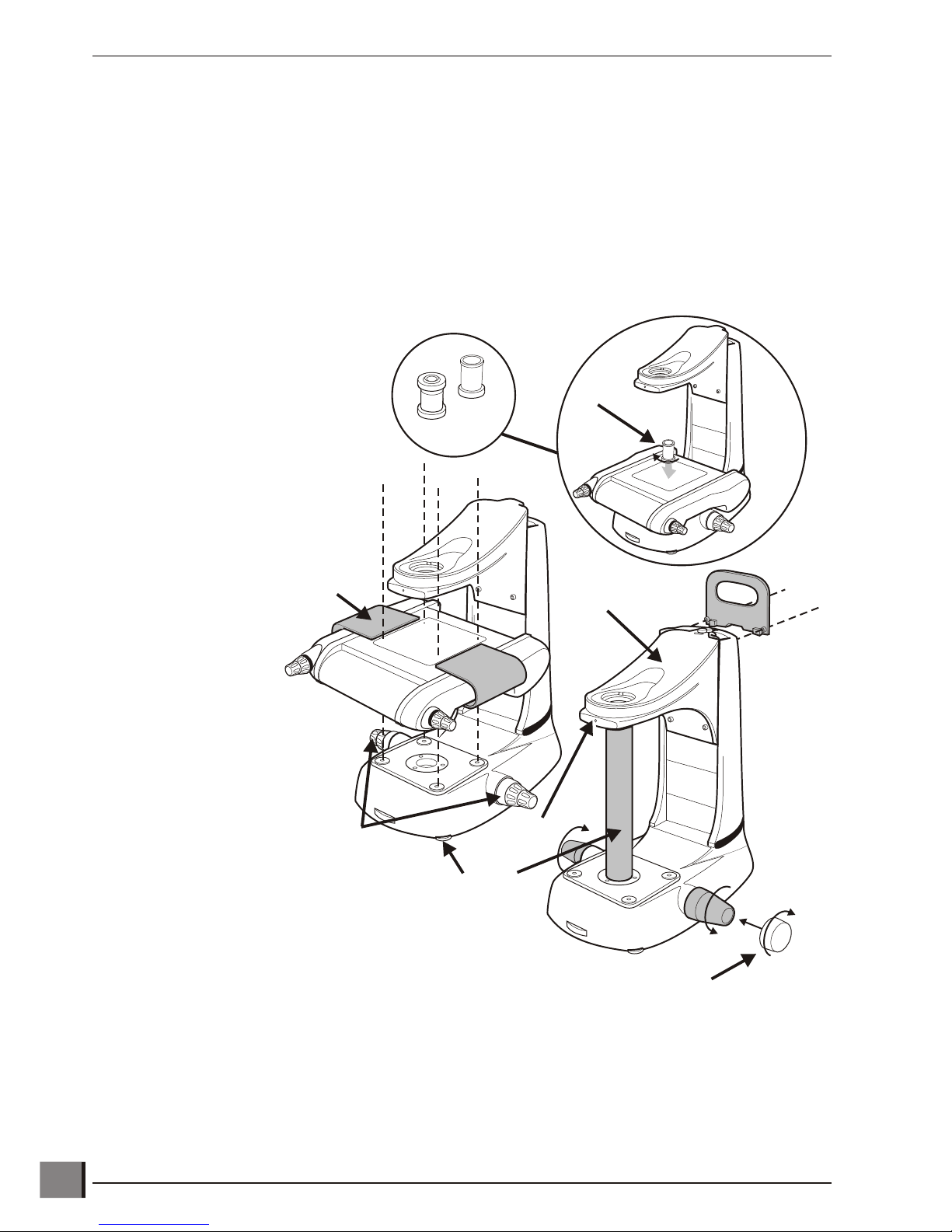
ASSEMBLYThe following paragraphs provide instructions on how to assemble the Hawk Measuring System. In most instances
the illustrations are self explanatory; where necessary the illustrations are supported by text.
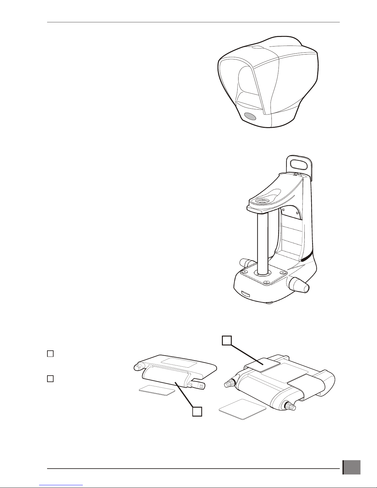
Stage assembly
To attach the Stage proceed as follows:
u Use the red transit handle and focus control covers to lift the stand into the required work position.
u Remove the red transit handle and focus
control covers. Screw the two focus
control collars u into position.
u Remove the grub screw v. Use the
focus controls w to raise the head
platform x until there is sufficient
room to unscrew and remove the
transit tube y.
u Using the red transit handles, lift the
stage into position and secure it
using the bolts provided
with the stand, not
the bolts that secure
the stage into the
transit box.
u Remove the stage
transit handles z.
u Adjust the stabilizing foot {
to support the stand base.
u Screw the required condenser
lens | through the stage and
into the stand.
Note: Micro condensers should only be used with micro
lenses when viewing a subject at stage glass level.
Hawk 2 or 3-Axis Manual Non-Contact Measuring System www.visioneng.com/support
ASSEMBLY
4
Micro
Macro
u
v
w
x
y
z
{
|
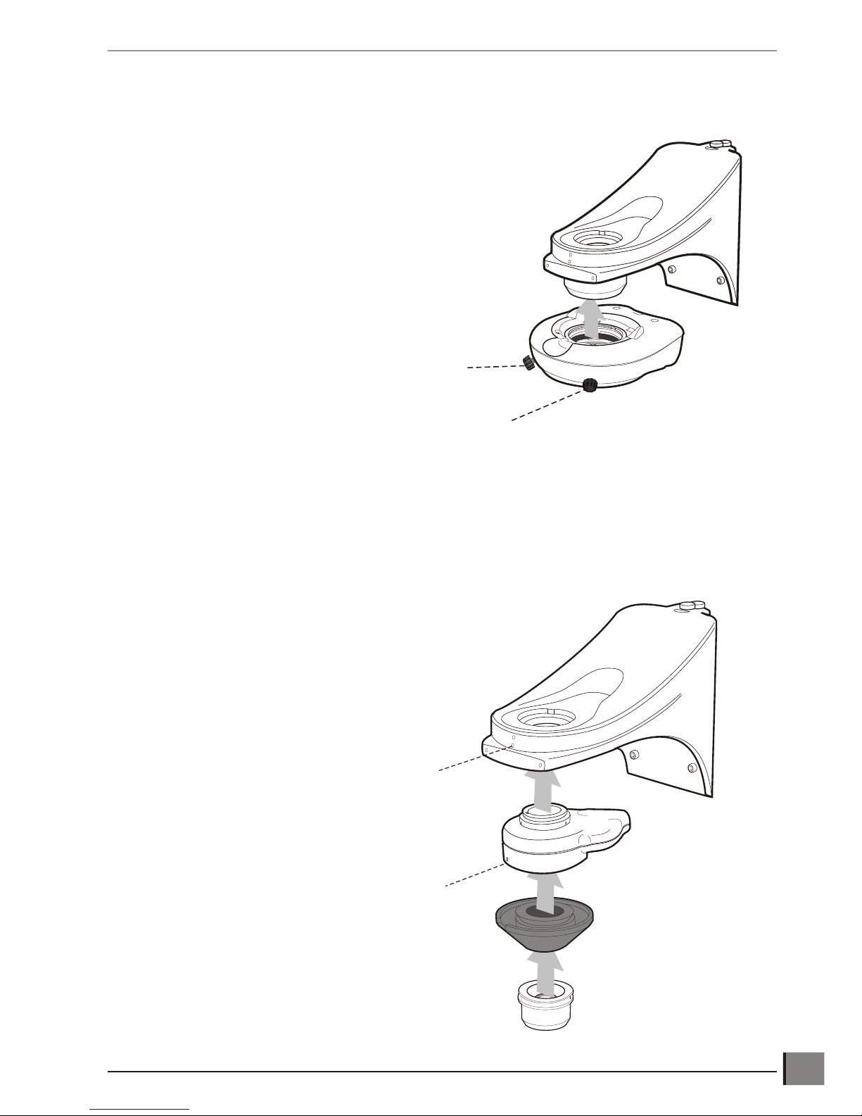
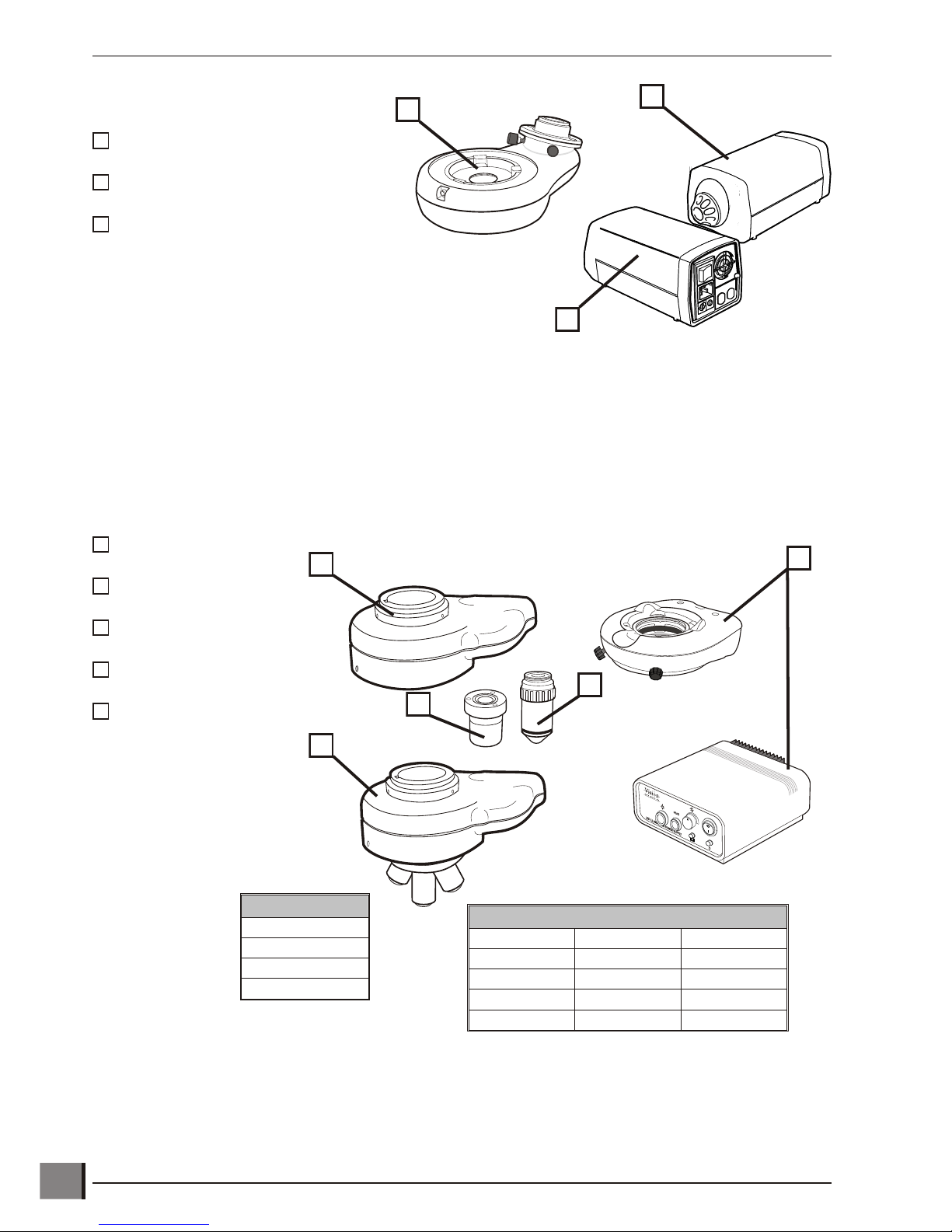
Ringlight attachment
Macro EPI attachment
Note: The same procedure is used to fit either the Macro EPI (illustrated) or the Micro EPI. The Micro
EPI cannot have an Objective Holder or Ringlight fitted.
www.visioneng.com/support Hawk 2 or 3-Axis Manual Non-Contact Measuring System
ASSEMBLY
5
Securing Screw
Grub Screw
Grub Screw
Securing Screw
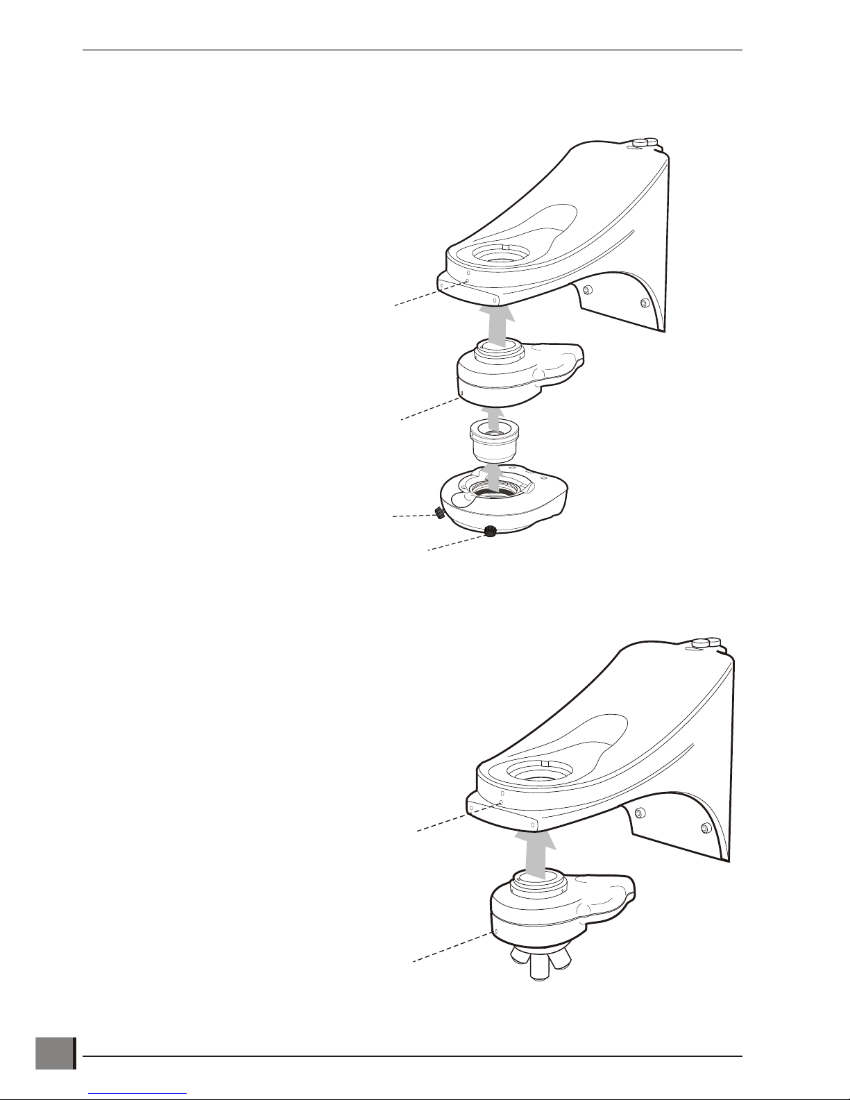
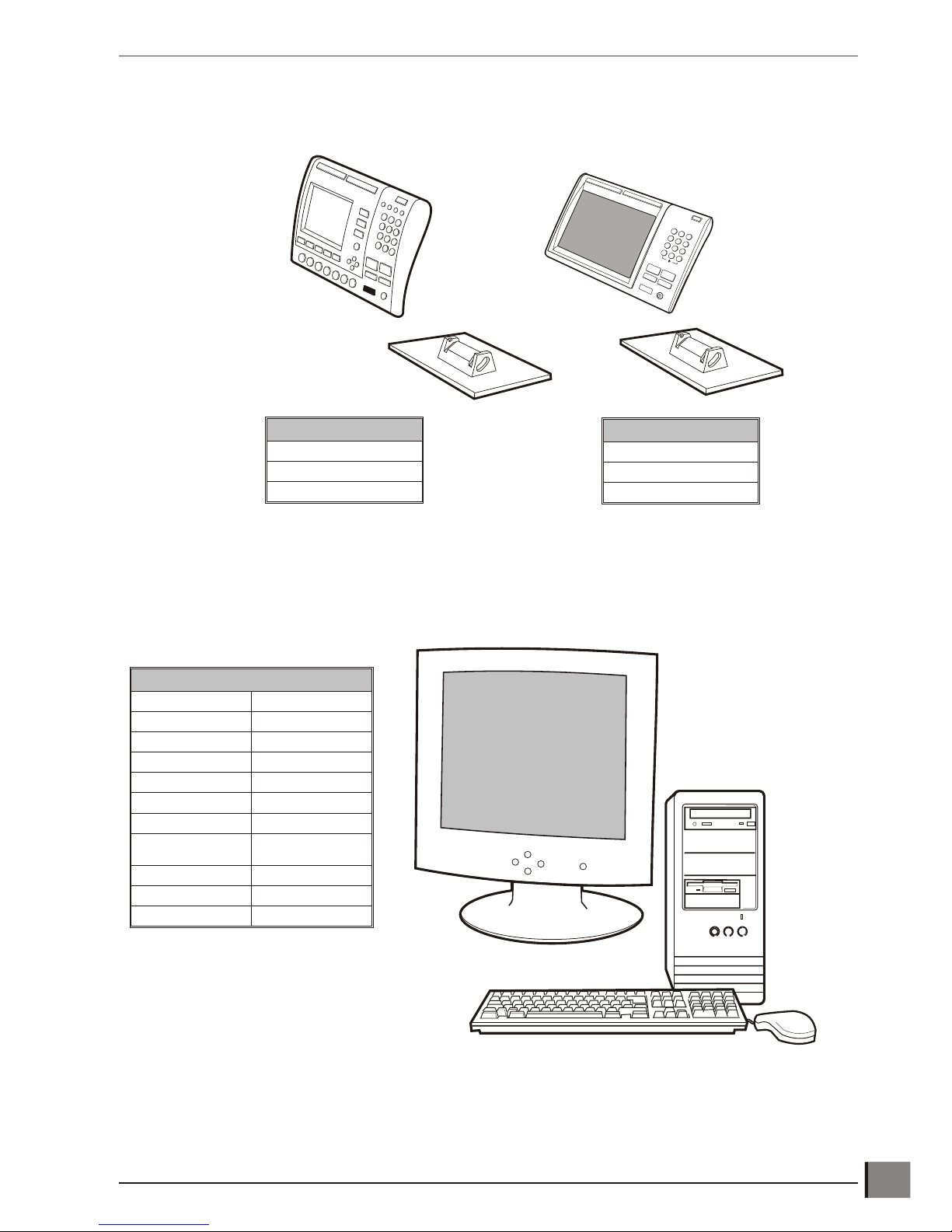
Macro EPI and ringlight attachment
Micro EPI and lens turret attachment
Hawk 2 or 3-Axis Manual Non-Contact Measuring System www.visioneng.com/support
ASSEMBLY
6
Grub Screw
Securing Screw
Grub Screw
Securing Screw
Grub Screw
Grub Screw
 Loading...